cc/td/doc/product/ong/15400/r60docs
hometocprevnextglossaryfeedbacksearchhelp
PDF

Table Of Contents

Configuring Networking Protocols

Basic IP Routing Protocol Configuration

RIP

EIGRP

OSPF

BGP

Enabling IP Routing

Configuring IP Routing

Configuring RIP

Configuring OSPF

Configuring EIGRP

Configure EIGRP Route Authentication

Border Gateway Protocol and Classless Interdomain Routing

Configuring IS-IS

Verifying the IS-IS Configuration

Configuring Static Routes

Monitoring Static Routes

Monitoring and Maintaining the IP Network

Understanding IP Multicast Routing

Configuring IP Multicast Routing

Monitoring and Verifying IP Multicast Operation


Configuring Networking Protocols


This chapter describes how to configure the ML-Series card for supported IP routing protocols. It is intended to provide enough information for a network administrator to get the protocols up and running. However, this section does not provide in-depth configuration detail for each protocol. For detailed information, refer to the Cisco IOS IP and IP Routing Configuration Guide and the Cisco IOS IP and IP Routing Command Reference publications.

This chapter contains the following major sections:

Basic IP Routing Protocol Configuration

Configuring IP Routing

Monitoring Static Routes

Monitoring and Maintaining the IP Network

Understanding IP Multicast Routing

Configuring IP Multicast Routing

Monitoring and Verifying IP Multicast Operation

Basic IP Routing Protocol Configuration

IP routing is enabled by default on the ML-Series card.

For IP routing, you need the following to configure your interface:

IP address

IP subnet mask

You also need to do the following:

Select a routing protocol.

Assign IP network numbers to be advertised.

The ML Series supports the routing protocols listed and described in the following sections.

To configure IP routing protocols to run on a Fast Ethernet, Gigabit Ethernet, or Packet-over-SONET/SDH (POS) interface, perform one of the following procedures, depending on the protocol you are configuring.

RIP

To configure the Routing Information Protocol (RIP), perform the following procedure, beginning in global configuration mode:

 
Command
Purpose

Step 1 

Router(config)# router rip

Enters router configuration mode, defines RIP as the routing protocol, and starts the RIP routing process.

Step 2 

Router(config-router)# network net-number

Specifies a directly connected network based on the Internet Network Information Center (InterNIC) network number—not a subnet number or individual address. The routing process associates interfaces with the appropriate addresses and begins processing packets on the specified network.

Step 3 

Router(config-router)# exit

Returns to global configuration mode.

EIGRP

To configure the Enhanced Interior Gateway Routing Protocol (EIGRP), perform the following procedure, beginning in global configuration mode:

 
Command
Purpose

Step 1 

Router(config)# router eigrp autonomous-system-number

Defines EIGRP as the IP routing protocol.

The autonomous system number is the autonomous system to which this ML-Series card belongs.

Step 2 

Router(config-router)# network net-number

Defines the directly connected networks that run EIGRP.

The network number is the number of the network that is advertised by this ML-Series card.

Step 3 

Router(config-router)# exit

Returns to global configuration mode.

OSPF

To configure the Open Shortest Path First (OSPF) protocol, perform the following procedure, beginning in global configuration mode:

 
Command
Purpose

Step 1 

Router(config)# router ospf process-ID

Defines OSPF as the IP routing protocol.

The process ID identifies a unique OSPF router process. This number is internal to the ML-Series card only; the process ID here does not have to match the process IDs on other routers.

Step 2 

Router(config-router)# network net-address wildcard-mask area area-ID

Assigns an interface to a specific area.

The net-address is the address of directly connected networks or subnets.

The wildcard-mask is an inverse mask that compares a given address with interface addressing to determine whether OSPF uses this interface.

The area parameter identifies the interface as belonging to an area.

The area-ID specifies the area associated with the network address.

Step 3 

Router(config-router)# end

Returns to privileged EXEC mode.

BGP

To configure the Border Gateway Protocol (BGP), perform the following procedure, beginning in global configuration mode:

 
Command
Purpose

Step 1 

Router(config)# router bgp autonomous-system-number

Defines BGP as the IP routing protocol.

The autonomous system number is the autonomous system to which this ML-Series card belongs.

Step 2 

Router(config-router) # network net-number

Defines the directly connected networks that run BGP.

The network number is the number of the network that is advertised by this ML-Series card.

Step 3 

Router(config-router)# exit

Returns to global configuration mode.

Enabling IP Routing

Beginning in privileged EXEC mode, follow this procedure to enable IP routing:


Note By default, IP routing is already enabled.


Command
Purpose

Step 1 

Router# configure terminal

Enters global configuration mode.

Step 2 

Router(config)# ip routing

Enables IP routing (default).

Step 3 

Router(config)# router ip-routing-protocol

Specifies an IP routing protocol. This step might include other commands, such as specifying the networks to route with the network (RIP) router configuration command. For information about specific protocols, refer to sections later in this chapter and to the Cisco IOS IP and IP Routing Configuration Guide.

Step 4 

Router(config-router)# end

Returns to privileged EXEC mode.

Step 5 

Router(config)# show running-config

Verifies your entries.

Step 6 

Router(config)# copy running-config startup-config

(Optional) Saves your entries in the configuration file.

Use the no ip routing global configuration command ( Example 11-1) to disable routing.

Example 11-1 Enabling IP Routing Using RIP as the Routing Protocol

Router# configure terminal
Router(config)# ip routing
Router(config)# router rip
Router(config-router)# network 10.0.0.0
Router(config-router)# end

Configuring IP Routing

You can now set up parameters for the selected routing protocols as described in these sections:

Configuring RIP

Configuring OSPF

Configuring EIGRP

Configuring BGP

Configuring IS-IS

Configuring Static Routes

Configuring RIP

The Routing Information Protocol (RIP) is an Interior Gateway Protocol (IGP) created for use in small, homogeneous networks. It is a distance-vector routing protocol that uses broadcast User Datagram Protocol (UDP) data packets to exchange routing information. The protocol is documented in RFC 1058. You can find detailed information about RIP in IP Routing Fundamentals, published by Cisco Press.

Using RIP, the switch sends routing information updates (advertisements) every 30 seconds. If a router does not receive an update from another router for 180 seconds or more, it marks the routes served by that router as unusable. If there is still no update after 240 seconds, the router removes all routing table entries for the nonupdating router.

RIP uses hop counts to rate the value of different routes. The hop count is the number of routers that can be traversed in a route. A directly connected network has a hop count of zero; a network with a hop count of 16 is unreachable. This small range (0 to 15) makes RIP unsuitable for large networks.

If the router has a default network path, RIP advertises a route that links the router to the pseudo network 0.0.0.0. The 0.0.0.0 network does not exist; it is treated by RIP as a network to implement the default routing feature. The switch advertises the default network if a default was learned by RIP or if the router has a gateway of last resort and RIP is configured with a default metric. RIP sends updates to the interfaces in specified networks. If an interface's network is not specified, it is not advertised in any RIP update.

Table 11-1 shows the default RIP configuration.

Table 11-1 Default RIP Configuration 

Feature
Default Setting

Auto summary

Enabled

Default-information originate

Disabled

Default metric

Built-in; automatic metric translations

IP RIP authentication key-chain

No authentication

Authentication mode: clear text

IP RIP receive version

According to the version router configuration command

IP RIP send version

According to the version router configuration command

IP RIP triggered

According to the version router configuration command

IP split horizon

Varies with media

Neighbor

None defined

Network

None specified

Offset list

Disabled

Output delay

0 milliseconds

Timers basic

Update: 30 seconds

Invalid: 180 seconds

Hold-down: 180 seconds

Flush: 240 seconds

Validate-update-source

Enabled

Version

Receives RIP Version 1 and Version 2 packets;
sends Version 1 packets


To configure RIP, enable RIP routing for a network and optionally configure other parameters.

Beginning in privileged EXEC mode, follow this procedure to enable and configure RIP:

 
Command
Purpose

Step 1 

Router# configure terminal

Enters global configuration mode.

Step 2 

Router(config)# ip routing

Enables IP routing. (Required only if IP routing is disabled.)

Step 3 

Router(config)# router rip

Enables a RIP routing process, and enters router configuration mode.

Step 4 

Router(config-router)# network network-number

Associates a network with a RIP routing process. You can specify multiple network commands. RIP routing updates are sent and received through interfaces only on these networks.

Step 5 

Router(config-router)# neighbor ip-address

(Optional) Defines a neighboring router with which to exchange routing information. This step allows routing updates from RIP (normally a broadcast protocol) to reach nonbroadcast networks.

Step 6 

Router(config-router)# offset list {[access-list-number | name]} {in | out} offset [type-number]

(Optional) Applies an offset list to routing metrics to increase incoming and outgoing metrics to routes learned through RIP. You can limit the offset list with an access list or an interface.

Step 7 

Router(config-router)# timers basic update invalid holddown flush

(Optional) Adjusts routing protocol timers. Valid ranges for all timers are 0 to 4294967295 seconds.

update—The time (in seconds) between sending of routing updates. The default is 30 seconds.

invalid—The timer interval (in seconds) after which a route is declared invalid. The default is 180 seconds.

holddown—The time (in seconds) that must pass before a route is removed from the routing table. The default is 180 seconds.

flush—The amount of time (in seconds) for which routing updates are postponed. The default is 240 seconds.

Step 8 

Router(config-router)# version {1 | 2}

(Optional) Configures the switch to receive and send only RIP Version 1 or RIP Version 2 packets. By default, the switch receives Version 1 and 2 but sends only Version 1.
You can also use the interface commands ip rip {send | receive} version {1 | 2 | 1 2} to control what versions are used for sending and receiving on interfaces.

Step 9 

Router(config-router)# no auto summary

(Optional) Disables automatic summarization. By default, the switch summarizes subprefixes when crossing classful network boundaries. Disables summarization (RIP Version 2 only) to advertise subnet and host routing information to classful network boundaries.

Step 10 

Router(config-router)# no validate-update-source

(Optional) Disables validation of the source IP address of incoming RIP routing updates. By default, the switch validates the source IP address of incoming RIP routing updates and discards the update if the source address is not valid. Under normal circumstances, disabling this feature is not recommended. However, if you have a router that is off-network and you want to receive its updates, you can use this command.

Step 11 

Router(config-router)# output-delay delay

(Optional) Adds interpacket delay for RIP updates sent. By default, packets in a multiple-packet RIP update have no delay added between packets. If you are sending packets to a lower-speed device, you can add an interpacket delay in the range of 8 to 50 milliseconds.

Step 12 

Router(config-router)# end

Returns to privileged EXEC mode.

Step 13 

Router# show ip protocols

Verifies your entries.

Step 14 

Router# copy running-config startup-config

(Optional) Saves your entries in the configuration file.

To turn off the RIP routing process, use the no router rip global configuration command.

To display the parameters and current state of the active routing protocol process, use the show ip protocols privileged EXEC command ( Example 11-2).

Example 11-2 show ip protocols Command Output (Showing RIP Processes)

Router# show ip protocols
Routing Protocol is "rip"
Sending updates every 30 seconds, next due in 15 seconds
Invalid after 180 seconds, hold down 180, flushed after 240
Outgoing update filter list for all interfaces is not set
Incoming update filter list for all interfaces is not set
Redistributing: rip
Default version control: send version 1, receive any version
Interface Send Recv Triggered RIP Key-chain
FastEthernet0 1 1 2
POS0 1 1 2
Automatic network summarization is in effect
Maximum path: 4
Routing for Networks:
192.168.2.0
192.168.3.0
Routing Information Sources:
Gateway Distance Last Update
192.168.2.1 120 00:00:23
Distance: (default is 120)

Use the show ip rip database privileged EXEC command to display summary address entries in the RIP database ( Example 11-3).

Example 11-3 show ip rip database Command Output

Router# show ip rip database
192.168.1.0/24 auto-summary
192.168.1.0/24
[1] via 192.168.2.1, 00:00:24, POS0
192.168.2.0/24 auto-summary
192.168.2.0/24 directly connected, POS0
192.168.3.0/24 auto-summary
192.168.3.0/24 directly connected, FastEthernet0

RIP Authentication

RIP Version 1 does not support authentication. If you are sending and receiving RIP Version 2 packets, you can enable RIP authentication on an interface. The key chain determines the set of keys that can be used on the interface. If a key chain is not configured, no authentication is performed, not even the default.

The switch supports two modes of authentication on interfaces for which RIP authentication is enabled: plain text and message-digest key (MD5). The default is plain text.

Beginning in privileged EXEC mode, follow this procedure to configure RIP authentication on an interface:

 
Command
Purpose

Step 1 

Router# configure terminal

Enters global configuration mode.

Step 2 

Router(config)# interface interface-id

Enters interface configuration mode, and specifies the interface to configure.

Step 3 

Router(config-if)# ip rip authentication key-chain name-of-chain

Enables RIP authentication.

Step 4 

Router(config-if)# ip rip authentication mode {text | md5}

Configures the interface to use plain text authentication (the default) or MD5 digest authentication.

Step 5 

Router(config-if)# end

Returns to privileged EXEC mode.

Step 6 

Router# show running-config interface [interface-id]

Verifies your entries.

Step 7 

Router# copy running-config startup-config

(Optional) Saves your entries in the configuration file.

To restore clear text authentication, use the no ip rip authentication mode interface configuration command. To prevent authentication, use the no ip rip authentication key-chain interface configuration command.

Summary Addresses and Split Horizon

Routers connected to broadcast-type IP networks and using distance-vector routing protocols normally use the split-horizon mechanism to reduce the possibility of routing loops. Split horizon blocks information about routes from being advertised by a router on any interface from which that information originated. This feature usually optimizes communication among multiple routers, especially when links are broken.


Note In general, disabling split horizon is not recommended unless you are certain that your application requires it to properly advertise routes.


If you want to configure an interface running RIP to advertise a summarized local IP address pool on a network access server for dial-up clients, use the ip summary-address rip interface configuration command.

Beginning in privileged EXEC mode, follow these steps to set an interface to advertise a summarized local IP address pool and to disable split horizon on the interface:

 
Command
Purpose

Step 1 

Router# configure terminal

Enters global configuration mode.

Step 2 

Router(config)# interface interface-id

Enters interface configuration mode, and specifies the Layer 3 interface to configure.

Step 3 

Router(config-if)# ip address ip-address subnet-mask

Configures the IP address and IP subnet.

Step 4 

Router(config-if)# ip summary-address rip ip-address ip-network-mask

Configures the IP address to be summarized and the IP network mask.

Step 5 

Router(config-if)# no ip split horizon

Disables split horizon on the interface.

Step 6 

Router(config-if)# end

Returns to privileged EXEC mode.

Step 7 

Router# show ip interface interface-id

Verifies your entries.

Step 8 

Router# copy running-config startup-config

(Optional) Saves your entries in the configuration file.

To disable IP summarization, use the no ip summary-address rip router configuration command.


Note If split horizon is enabled, neither autosummary nor interface summary addresses (those configured with the ip summary-address rip router configuration command) are advertised.


Configuring OSPF

This section briefly describes how to configure the Open Shortest Path First (OSPF) protocol. For a complete description of the OSPF commands, refer to the "OSPF Commands" chapter of the Cisco IOS IP and IP Routing Command Reference publication.

OSPF is an IGP designed expressly for IP networks, supporting IP subnetting and tagging of externally derived routing information. OSPF also allows packet authentication and uses IP multicast when sending and receiving packets. The Cisco implementation supports RFC 1253, the OSPF MIB.

The Cisco implementation conforms to the OSPF Version 2 specifications with these key features:

Stub areas—Definition of stub areas is supported.

Route redistribution—Routes learned through any IP routing protocol can be redistributed into another IP routing protocol. At the intradomain level, this means that OSPF can import and export routes learned through protocols such as EIGRP and RIP.

Authentication—Plain text and MD5 authentication among neighboring routers within an area are supported.

Routing interface parameter—Configurable parameters supported include interface output cost, retransmission interval, interface transmit delay, router priority, router dead and hello intervals, and authentication key.

Virtual links—Virtual links are supported.

Not-so-stubby-area (NSSA)—RFC 1587.

OSPF typically requires coordination among many internal routers, area border routers (ABRs) connected to multiple areas, and autonomous system boundary routers (ASBRs). The minimum configuration would use all default parameter values, no authentication, and interfaces assigned to areas. If you customize your environment, you must ensure coordinated configuration of all routers.

Table 11-2 shows the default OSPF configuration.

Table 11-2 Default OSPF Configuration 

Feature
Default Setting

Interface parameters

Cost: No default cost predefined.

Retransmit interval: 5 seconds.

Transmit delay: 1 second.

Priority: 1.

Hello interval: 10 seconds.

Dead interval: 4 times the hello interval.

No authentication.

No password specified.

MD5 authentication disabled.

Area

Authentication type: 0 (no authentication).

Default cost: 1.

Range: Disabled.

Stub: No stub area defined.

NSSA: No NSSA area defined.

Auto cost

100 Mbps.

Default-information originate

Disabled. When enabled, the default metric setting is 10, and the external route type default is Type 2.

Default metric

Built-in, automatic metric translation, as appropriate for each routing protocol.

Distance OSPF

dist1 (all routes within an area): 110
dist2 (all routes from one area to another): 110
dist3 (routes from other routing domains): 110

OSPF database filter

Disabled. All outgoing link-state advertisements (LSAs) are flooded to the interface.

IP OSPF name lookup

Disabled.

Log adjacency changes

Enabled.

Neighbor

None specified.

Neighbor database filter

Disabled. All outgoing LSAs are flooded to the neighbor.

Network area

Disabled.

Router ID

No OSPF routing process defined.

Summary address

Disabled.

Timers LSA group pacing

240 seconds.

Timers shortest path first (spf)

spf delay: 5 seconds.

spf-holdtime: 10 seconds.

Virtual link

No area ID or router ID defined.

Hello interval: 10 seconds.

Retransmit interval: 5 seconds.

Transmit delay: 1 second.

Dead interval: 40 seconds.

Authentication key: No key predefined.

MD5: No key predefined.


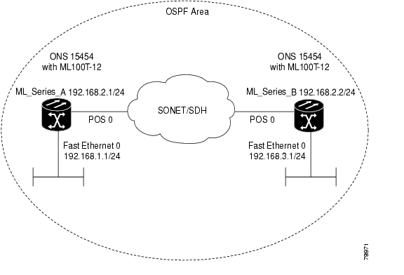
Figure 11-1 shows an example of an IP routing protocol using OSPF.

Figure 11-1 IP Routing Protocol Example Using OSPF

Enabling OSPF requires that you create an OSPF routing process, specify the range of IP addresses to be associated with the routing process, and assign area IDs to be associated with that range.

Beginning in privileged EXEC mode, follow this procedure to enable OSPF:

 
Command
Purpose

Step 1 

Router# configure terminal

Enters global configuration mode.

Step 2 

Router(config)# router ospf process-id

Enables OSPF routing, and enters router configuration mode. The process ID is an internally used identification parameter that is locally assigned and can be any positive integer. Each OSPF routing process has a unique value.

Step 3 

Router(config)# network address wildcard-mask area area-id

Defines an interface on which OSPF runs and the area ID for that interface. Use the wildcard-mask to use a single command to define one or more multiple interfaces to be associated with a specific OSPF area. The area ID can be a decimal value or an IP address.

Step 4 

Router(config)# end

Returns to privileged EXEC mode.

Step 5 

Router# show ip protocols

Verifies your entries.

Step 6 

Router# copy running-config startup-config

(Optional) Saves your entries in the configuration file.

To terminate an OSPF routing process, use the no router ospf process-id global configuration command.

Example 11-4 shows an example of configuring an OSPF routing process. In the example, a process number of 1 is assigned. Example 11-5 shows the output of the command used to verify the OSPF process ID.

Example 11-4 Configuring an OSPF Routing Process

Router(config)# router ospf 1
Router(config-router)# network 192.168.1.0 0.0.0.255 area 0

Example 11-5 show ip protocols Privileged EXEC Command Output

Router# show ip protocols
Routing Protocol is "ospf 1"
Outgoing update filter list for all interfaces is not set
Incoming update filter list for all interfaces is not set
Router ID 192.168.3.1
Number of areas in this router is 1. 1 normal 0 stub 0 nssa
Maximum path: 4
Routing for Networks:
192.168.2.0 0.0.0.255 area 0
192.168.3.0 0.0.0.255 area 0
Routing Information Sources:
Gateway Distance Last Update
192.168.3.1 110 00:03:34
192.168.2.1 110 00:03:34
Distance: (default is 110)

OSPF Interface Parameters

You can use the ip ospf interface configuration commands to modify interface-specific OSPF parameters. You are not required to modify any of these parameters, but some interface parameters (hello interval, dead interval, and authentication key) must be consistent across all routers in an attached network. If you modify these parameters, be sure all routers in the network have compatible values.


Note The ip ospf interface configuration commands are all optional.


Beginning in privileged EXEC mode, follow these steps to modify OSPF interface parameters:

 
Command
Purpose

Step 1 

Router# configure terminal

Enters global configuration mode.

Step 2 

Router(config)# interface interface-id

Enters interface configuration mode, and specifies the Layer 3 interface to configure.

Step 3 

Router(config-if)# ip ospf cost

(Optional) Explicitly specifies the cost of sending a packet on the interface.

Step 4 

Router(config-if)# ip ospf retransmit-interval seconds

(Optional) Specifies the number of seconds between link state advertisement transmissions. The range is 1 to 65535 seconds. The default is 5 seconds.

Step 5 

Router(config-if)# ip ospf transmit-delay seconds

(Optional) Sets the estimated number of seconds to wait before sending a link state update packet. The range is 1 to 65535 seconds. The default is 1 second.

Step 6 

Router(config-if)# ip ospf priority number

(Optional) Sets priority to help determine the OSPF designated router for a network. The range is from 0 to 255. The default is 1.

Step 7 

Router(config-if)# ip ospf hello-interval seconds

(Optional) Sets the number of seconds between hello packets sent on an OSPF interface. The value must be the same for all nodes on a network. The range is 1 to 65535 seconds. The default is 10 seconds.

Step 8 

Router(config-if)# ip ospf dead-interval seconds

(Optional) Sets the number of seconds after the last device hello packet was seen before its neighbors declare the OSPF router to be down. The value must be the same for all nodes on a network. The range is 1 to 65535 seconds. The default is 4 times the hello interval.

Step 9 

Router(config-if)# ip ospf authentication-key key

(Optional) Assigns a password to be used by neighboring OSPF routers. The password can be any string of keyboard-entered characters up to 8 bytes in length. All neighboring routers on the same network must have the same password to exchange OSPF information.

Step 10 

Router(config-if)# ip ospf message digest-key keyid md5 key

(Optional) Enables authentication.

keyid—Identifier from 1 to 255.

key—Alphanumeric password of up to 16 bytes.

Step 11 

Router(config-if)# ip ospf database-filter all out

(Optional) Blocks flooding of OSPF LSA packets to the interface. By default, OSPF floods new LSAs over all interfaces in the same area, except the interface on which the LSA arrives.

Step 12 

Router(config-if)# end

Returns to privileged EXEC mode.

Step 13 

Router# show ip ospf interface [interface-name]

Displays OSPF-related interface information.

Step 14 

Router# copy running-config startup-config

(Optional) Saves your entries in the configuration file.

Use the no form of these commands to remove the configured parameter value or return to the default value. Example 11-6 shows the output of the show ip ospf interface privileged EXEC command.

Example 11-6 show ip ospf interface Privileged EXEC Command Output

Router# show ip ospf interface
FastEthernet0 is up, line protocol is up
Internet Address 192.168.3.1/24, Area 0
Process ID 1, Router ID 192.168.3.1, Network Type BROADCAST, Cost: 1
Transmit Delay is 1 sec, State DR, Priority 1
Designated Router (ID) 192.168.3.1, Interface address 192.168.3.1
No backup designated router on this network
Timer intervals configured, Hello 10, Dead 40, Wait 40, Retransmit 5
Hello due in 00:00:01
Index 2/2, flood queue length 0
Next 0x0(0)/0x0(0)
Last flood scan length is 0, maximum is 0
Last flood scan time is 0 msec, maximum is 0 msec
Neighbor Count is 0, Adjacent neighbor count is 0
Suppress hello for 0 neighbor(s)
POS0 is up, line protocol is up
Internet Address 192.168.2.2/24, Area 0
Process ID 1, Router ID 192.168.3.1, Network Type BROADCAST, Cost: 1
Transmit Delay is 1 sec, State DR, Priority 1
Designated Router (ID) 192.168.3.1, Interface address 192.168.2.2
Backup Designated router (ID) 192.168.2.1, Interface address 192.168.2.1
Timer intervals configured, Hello 10, Dead 40, Wait 40, Retransmit 5
Hello due in 00:00:05
Index 1/1, flood queue length 0
Next 0x0(0)/0x0(0)
Last flood scan length is 2, maximum is 2
Last flood scan time is 0 msec, maximum is 0 msec
Neighbor Count is 1, Adjacent neighbor count is 1
Adjacent with neighbor 192.168.2.1 (Backup Designated Router)
Suppress hello for 0 neighbor(s)

OSPF Area Parameters

You can optionally configure several OSPF area parameters. These parameters include authentication for password-based protection against unauthorized access to an area, stub areas, and NSSAs. Stub areas are areas into which information about external routes is not sent. Instead, the ABR generates a default external route into the stub area for destinations outside the autonomous system (AS). An NSSA does not flood all LSAs from the core into the area, but can import AS external routes within the area by redistribution.

Route summarization is the consolidation of advertised addresses into a single summary route to be advertised by other areas. If network numbers are contiguous, you can use the area range router configuration command to configure the ABR to advertise a summary route that covers all networks in the range.


Note The OSPF area router configuration commands are all optional.


Beginning in privileged EXEC mode, follow these steps to configure area parameters:

 
Command
Purpose

Step 1 

Router# configure terminal

Enters global configuration mode.

Step 2 

Router(config)# router ospf process-id

Enables OSPF routing, and enters router configuration mode.

Step 3 

Router(config)# area area-id authentication

(Optional) Allows password-based protection against unauthorized access to the identified area. The identifier can be either a decimal value or an IP address.

Step 4 

Router(config)# area area-id authentication message-digest

(Optional) Enables MD5 authentication on the area.

Step 5 

Router(config)# area area-id stub [no-summary]

(Optional) Defines an area as a stub area. The no-summary keyword prevents an ABR from sending summary link advertisements into the stub area.

Step 6 

Router(config)# area area-id nssa {no-redistribution | default-information-originate | no-summary}

(Optional) Defines an area as a not-so-stubby-area. Every router within the same area must agree that the area is NSSA. Select one of these keywords:

no-redistribution—Select when the router is an NSSA ABR and you want the redistribute command to import routes into normal areas, but not into the NSSA.

default-information-originate—Select on an ABR to allow importing type 7 LSAs into the NSSA.

no-redistribution—Select to not send summary LSAs into the NSSA.

Step 7 

Router(config)# area area-id range address-mask

(Optional) Specifies an address range for which a single route is advertised. Use this command only with area border routers.

Step 8 

Router(config)# end

Returns to privileged EXEC mode.

Step 9 

Router# show ip ospf [process-id]

Displays information about the OSPF routing process in general or for a specific process ID to verify configuration.

Step 10 

Router# copy running-config startup-config

(Optional) Saves your entries in the configuration file.

Use the no form of these commands to remove the configured parameter value or to return to the default value. Example 11-7 shows the output of the show ip ospf database and the show ip ospf privileged EXEC commands.

Example 11-7 show ip ospf database and show ip ospf Privileged EXEC Command Ouputs

Router# show ip ospf database

OSPF Router with ID (192.168.3.1) (Process ID 1)


Router Link States (Area 0)

Link ID ADV Router Age Seq# Checksum Link count
192.168.2.1 192.168.2.1 428 0x80000003 0x004AB8 2
192.168.3.1 192.168.3.1 428 0x80000003 0x006499 2

Net Link States (Area 0)

Link ID ADV Router Age Seq# Checksum
192.168.2.2 192.168.3.1 428 0x80000001 0x00A4E0

Router# show ip ospf
Routing Process "ospf 1" with ID 192.168.3.1
Supports only single TOS(TOS0) routes
Supports opaque LSA
SPF schedule delay 5 secs, Hold time between two SPFs 10 secs
Minimum LSA interval 5 secs. Minimum LSA arrival 1 secs
Number of external LSA 0. Checksum Sum 0x000000
Number of opaque AS LSA 0. Checksum Sum 0x000000
Number of DCbitless external and opaque AS LSA 0
Number of DoNotAge external and opaque AS LSA 0
Number of areas in this router is 1. 1 normal 0 stub 0 nssa
External flood list length 0
Area BACKBONE(0)
Number of interfaces in this area is 2
Area has no authentication
SPF algorithm executed 4 times
Area ranges are
Number of LSA 3. Checksum Sum 0x015431
Number of opaque link LSA 0. Checksum Sum 0x000000
Number of DCbitless LSA 0
Number of indication LSA 0
Number of DoNotAge LSA 0
Flood list length 0

Other OSPF Behavior Parameters

You can optionally configure other OSPF parameters in router configuration mode:

Route summarization—When redistributing routes from other protocols, each route is advertised individually in an external LSA. To help decrease the size of the OSPF link state database, you can use the summary-address router configuration command to advertise a single router for all the redistributed routes included in a specified network address and mask.

Virtual links—In OSPF, all areas must be connected to a backbone area. You can establish a virtual link in case of a backbone-continuity break by configuring two ABRs as endpoints of a virtual link. Configuration information includes the identity of the other virtual endpoint (the other ABR) and the nonbackbone link that the two routers have in common (the transit area). Virtual links cannot be configured through a stub area.

Default route—When you specifically configure redistribution of routes into an OSPF routing domain, the route automatically becomes an ASBR. You can force the ASBR to generate a default route into the OSPF routing domain.

Domain Name Server (DNS) names for use in all OSPF show privileged EXEC command displays make it easier to identify a router than displaying it by router ID or neighbor ID.

Default metrics—OSPF calculates the OSPF metric for an interface according to the bandwidth of the interface. The metric is calculated as ref-bw divided by bandwidth, where ref is 10 by default, and bandwidth (bw) is determined by the bandwidth interface configuration command. For multiple links with high bandwidth, you can specify a larger number to differentiate the cost on those links.

Administrative distance—This is a rating of the trustworthiness of a routing information source, an integer between 0 and 255, with a higher value meaning a lower trust rating. An administrative distance of 255 means that the routing information source cannot be trusted at all and should be ignored. OSPF uses three different administrative distances: routes within an area (intra-area), routes to another area (interarea), and routes from another routing domain learned through redistribution (external). You can change any of the distance values.

Passive interfaces—Because interfaces between two devices on an Ethernet represent only one network segment, to prevent OSPF from sending hello packets for the sending interface, you must configure the sending device to be a passive interface. Both devices can identify each other through the hello packet for the receiving interface.

Route calculation timers—You can configure the delay time between when OSPF receives a topology change and when it starts the shortest path first (SPF) calculation. You can also configure the hold time between two SPF calculations.

Log neighbor changes—You can configure the router to send a syslog message when an OSPF neighbor state changes, providing a high-level view of changes in the router.

Beginning in privileged EXEC mode, follow this procedure to configure these OSPF parameters:

 
Command
Purpose

Step 1 

Router# configure terminal

Enters global configuration mode.

Step 2 

Router(config)# router ospf process-id

Enables OSPF routing, and enters router configuration mode.

Step 3 

Router(config)# summary-address address-mask

(Optional) Specifies an address and IP subnet mask for redistributed routes so that only one summary route is advertised.

Step 4 

Router(config)# area area-id virtual-link router-id [hello-interval seconds] [retransmit-interval seconds] [trans] {[authentication-key key] | [message-digest-key key-id md5 key]}

(Optional) Establishes a virtual link and set its parameters. See the "OSPF Interface Parameters" section for parameter definitions and Table 11-2 for virtual link defaults.

Step 5 

Router(config)# default-information originate [always] [metric metric-value] [metric-type type-value] [route-map map-name]

(Optional) Forces the ASBR to generate a default route into the OSPF routing domain. Parameters are all optional.

Step 6 

Router(config)# ip ospf name-lookup

(Optional) Configures DNS name lookup. The default is disabled.

Step 7 

Router(config)# ip auto-cost reference-bandwidth ref-bw

(Optional) Specifies an address range for which a single route will be advertised. Use this command only with area border routers.

Step 8 

Router(config)# distance ospf {[inter-area dist1] | [inter-area dist2] | [external dist3]}

(Optional) Changes the OSPF distance values. The default distance for each type of route is 110. The range is 1 to 255.

Step 9 

Router(config)# passive-interface type number

(Optional) Suppresses the sending of hello packets through the specified interface.

Step 10 

Router(config)# timers spf spf-delay spf-holdtime

(Optional) Configures route calculation timers.

spf-delay—Enter an integer from 0 to 65535. The default is 5 seconds; 0 means no delay.

spf-holdtime—Enter an integer from 0 to 65535. The default is 10 seconds; 0 means no delay.

Step 11 

Router(config)# ospf log-adj-changes

(Optional) Sends syslog message when a neighbor state changes.

Step 12 

Router(config)# end

Returns to privileged EXEC mode.

Step 13 

Router# show ip ospf [process-id [area-id]] database

Displays lists of information related to the OSPF database for a specific router. For some of the keyword options, see to the "Monitoring OSPF" section.

Step 14 

Router# copy running-config startup-config

(Optional) Saves your entries in the configuration file.

Change LSA Group Pacing

The OSPF LSA group pacing feature allows the router to group OSPF LSAs and pace the refreshing, check-summing, and aging functions for more efficient router use. This feature is enabled by default with a four-minute default pacing interval, and you do not usually need to modify this parameter. The optimum group pacing interval is inversely proportional to the number of LSAs the router is refreshing, check-summing, and aging. For example, if you have approximately 10,000 LSAs in the database, decreasing the pacing interval would benefit you. If you have a very small database (40 to 100 LSAs), increasing the pacing interval to 10 to 20 minutes might benefit you slightly.

Beginning in privileged EXEC mode, follow this procedure to configure OSPF LSA pacing:

 
Command
Purpose

Step 1 

Router# configure terminal

Enters global configuration mode.

Step 2 

Router(config)# router ospf process-id

Enables OSPF routing, and enters router configuration mode.

Step 3 

Router(config)# timers lsa-group-pacing seconds

Changes the group pacing of LSAs.

Step 4 

Router(config)# end

Returns to privileged EXEC mode.

Step 5 

Router# show running-config

Verifies your entries.

Step 6 

Router# copy running-config startup-config

(Optional) Saves your entries in the configuration file.

To return to the default value, use the no timers lsa-group-pacing router configuration command.

Loopback Interface

OSPF uses the highest IP address configured on the interfaces as its router ID. If this interface is down or removed, the OSPF process must recalculate a new router ID and resend all its routing information out of its interfaces. If a loopback interface is configured with an IP address, OSPF uses this IP address as its router ID, even if other interfaces have higher IP addresses. Because loopback interfaces never fail, this provides greater stability. OSPF automatically prefers a loopback interface over other interfaces, and it chooses the highest IP address among all loopback interfaces.

Beginning in privileged EXEC mode, follow this procedure to configure a loopback interface:

 
Command
Purpose

Step 1 

Router# configure terminal

Enters global configuration mode.

Step 2 

Router(config)# interface loopback 0

Creates a loopback interface, and enters interface configuration mode.

Step 3 

Router(config)# ip address address mask

Assigns an IP address to this interface.

Step 4 

Router(config)# end

Returns to privileged EXEC mode.

Step 5 

Router# show ip interface

Verifies your entries.

Step 6 

Router# copy running-config startup-config

(Optional) Saves your entries in the configuration file.

Use the no interface loopback 0 global configuration command to disable the loopback interface.

Monitoring OSPF

You can display specific statistics such as the contents of IP routing tables, caches, and databases.

Table 11-3 lists some of the privileged EXEC commands for displaying statistics. For more show ip ospf database privileged EXEC command options and for explanations of fields in the resulting display, refer to the Cisco IOS IP and IP Routing Command Reference.

Table 11-3 Show IP OSPF Statistics Commands 

Command
Purpose
Router(config)# show ip ospf [process-id]

Displays general information about OSPF routing processes.

Router(config)# show ip ospf [process-id] database [router] [link-state-id]

Displays lists of information related to the OSPF database.

Router(config)# show ip ospf border-routes

Displays the internal OSPF routing ABR and ASBR table entries.

Router(config)# show ip ospf interface [interface-name]

Displays OSPF-related interface information.

Router(config)# show ip ospf neighbor [interface-name] [neighbor-id] detail

Displays OSPF interface neighbor information.

Router(config)# show ip ospf virtual-links

Displays OSPF-related virtual links information.


Configuring EIGRP

Enhanced IGRP (EIGRP) is a Cisco proprietary enhanced version of the Interior Gateway Routing Protocol (IGRP). Enhanced IGRP uses the same distance vector algorithm and distance information as IGRP; however, the convergence properties and the operating efficiency of Enhanced IGRP are significantly improved.

The convergence technology employs an algorithm referred to as the Diffusing Update Algorithm (DUAL), which guarantees loop-free operation at every instant throughout a route computation and allows all devices involved in a topology change to synchronize at the same time. Routers that are not affected by topology changes are not involved in recomputations.

IP EIGRP provides increased network width. With RIP, the largest possible width of your network is 15 hops. When IGRP is enabled, the largest possible width is 224 hops. Because the EIGRP metric is large enough to support thousands of hops, the only barrier to expanding the network is the transport-layer hop counter. EIGRP increments the transport control field only when an IP packet has traversed 15 routers and the next hop to the destination was learned through EIGRP. When a RIP route is used as the next hop to the destination, the transport control field is incremented as usual.

EIGRP offers the following features:

Fast convergence

Incremental updates when the state of a destination changes, instead of sending the entire contents of the routing table, minimizing the bandwidth required for EIGRP packets

Less CPU usage than IGRP because full update packets do not need to be processed each time they are received

Protocol-independent neighbor discovery mechanism to learn about neighboring routers

Variable-length subnet masks (VLSMs)

Arbitrary route summarization

EIGRP scales to large networks

EIGRP has four basic components:

Neighbor discovery and recovery is the process that routers use to dynamically learn of other routers on their directly attached networks. Routers must also discover when their neighbors become unreachable or inoperative. Neighbor discovery and recovery is achieved with low overhead by periodically sending small hello packets. As long as hello packets are received, the Cisco IOS software can determine that a neighbor is alive and functioning. When this status is determined, the neighboring routers can exchange routing information.

The reliable transport protocol is responsible for guaranteed, ordered delivery of EIGRP packets to all neighbors. It supports intermixed transmission of multicast and unicast packets. Some EIGRP packets must be sent reliably, and others need not be. For efficiency, reliability is provided only when necessary. For example, on a multiaccess network that has multicast capabilities (such as Ethernet), it is not necessary to send hellos reliably to all neighbors individually. Therefore, EIGRP sends a single multicast hello with an indication in the packet informing the receivers that the packet need not be acknowledged. Other types of packets (such as updates) require acknowledgment, which is shown in the packet. The reliable transport has a provision to send multicast packets quickly when there are unacknowledged packets pending. Doing so helps ensure that convergence time remains low in the presence of varying speed links.

The DUAL finite state machine embodies the decision process for all route computations. It tracks all routes advertised by all neighbors. DUAL uses the distance information (known as a metric) to select efficient, loop-free paths. DUAL selects routes to be inserted into a routing table based on feasible successors. A successor is a neighboring router used for packet forwarding that has a least-cost path to a destination that is guaranteed not to be part of a routing loop. When there are no feasible successors, but there are neighbors advertising the destination, a recomputation must occur. This is the process whereby a new successor is determined. The amount of time it takes to recompute the route affects the convergence time. Recomputation is processor-intensive; it is advantageous to avoid recomputation if it is not necessary. When a topology change occurs, DUAL tests for feasible successors. If there are feasible successors, it uses any it finds to avoid unnecessary recomputation.

The protocol-dependent modules are responsible for network layer protocol-specific tasks. An example is the IP EIGRP module, which is responsible for sending and receiving EIGRP packets that are encapsulated in IP. It is also responsible for parsing EIGRP packets and informing DUAL of the new information received. EIGRP asks DUAL to make routing decisions, but the results are stored in the IP routing table. EIGRP is also responsible for redistributing routes learned by other IP routing protocols.

Table 11-4 shows the default EIGRP configuration.

Table 11-4 Default EIGRP Configuration 

Feature
Default Setting

Auto summary

Enabled. Subprefixes are summarized to the classful network boundary when crossing classful network boundaries.

Default-information

Exterior routes are accepted and default information is passed between IGRP or EIGRP processes when doing redistribution.

Default metric

Only connected routes and interface static routes can be redistributed without a default metric. The metric includes:

Bandwidth: 0 or greater kbps.

Delay (tens of microseconds): 0 or any positive number that is a multiple of 39.1 nanoseconds.

Reliability: Any number between 0 and 255 (255 means 100 percent reliability).

Loading: Effective bandwidth as a number between 0 and 255 (255 is 100 percent loading).

MTU: Maximum transmission unit size of the route in bytes. 0 or any positive integer.

Distance

Internal distance: 90.

External distance: 170.

EIGRP log-neighbor changes

Disabled. No adjacency changes logged.

IP authentication key-chain

No authentication provided.

IP authentication mode

No authentication provided.

IP bandwidth-percent

50 percent.

IP hello interval

For low-speed nonbroadcast multiaccess (NBMA) networks: 60 seconds; all other networks: 5 seconds.

IP hold-time

For low-speed NBMA networks: 180 seconds; all other networks: 15 seconds.

IP split-horizon

Enabled.

IP summary address

No summary aggregate addresses are predefined.

Metric weights

tos: 0

k1 and k3: 1

k2, k4, and k5: 0

Network

None specified.

Offset-list

Disabled.

Router EIGRP

Disabled.

Set metric

No metric set in the route map.

Traffic-share

Distributed proportionately to the ratios of the metrics.

Variance

1 (equal-cost load balancing).


To create an EIGRP routing process, you must enable EIGRP and associate networks. EIGRP sends updates to the interfaces in the specified networks. If you do not specify an interface network, it is not advertised in any EIGRP update.

EIGRP Router Mode Commands

Beginning in privileged EXEC mode, follow these steps to configure EIGRP. Configuring the routing process is required; other steps are optional.

 
Command
Purpose

Step 1 

Router# configure terminal

Enters global configuration mode.

Step 2 

Router(config)# router eigrp autonomous-system-number

Enables an EIGRP routing process, and enters router configuration mode. The autonomous system number identifies the routes to other EIGRP routers and is used to tag routing information.

Step 3 

Router(config)# network network-number

Associates networks with an EIGRP routing process. EIGRP sends updates to the interfaces in the specified networks. If an interface's network is not specified, it is not advertised in any IGRP or EIGRP update.

Step 4 

Router(config)# eigrp log-neighbor-changes

(Optional) Enables logging of EIGRP neighbor changes to monitor routing system stability.

Step 5 

Router(config)# metric weights tos k1 k2 k3 k4 k5

(Optional) Adjusts the EIGRP metric. Although the defaults have been carefully determined to provide excellent operation in most networks, you can adjust them.


Caution Determining metrics is complex and is not recommended without guidance from an experienced network designer.

Step 6 

Router(config)# offset list [{access-list-number | name}] { in | out } offset [type-number]

(Optional) Applies an offset list to routing metrics to increase incoming and outgoing metrics to routes learned through EIGRP. You can limit the offset list with an access list or an interface.

Step 7 

Router(config)# no auto-summary

(Optional) Disables automatic summarization of subnet routes into network-level routes.

Step 8 

Router(config)# ip summary-address eigrp autonomous-system-number address-mask

(Optional) Configures a summary aggregate.

Step 9 

Router(config)# end

Returns to privileged EXEC mode.

Step 10 

Router# show ip protocols

Verifies your entries.

Step 11 

Router# copy running-config startup-config

(Optional) Saves your entries in the configuration file.

Use the no forms of these commands to disable the feature or return the setting to the default value. Example 11-8 shows the output for the show ip protocols privileged EXEC command.

Example 11-8 show ip protocols privileged EXEC Command Output (for EIGRP)

Router# show ip protocols

Routing Protocol is "eigrp 1"

Outgoing update filter list for all interfaces is not set

Incoming update filter list for all interfaces is not set

Default networks flagged in outgoing updates

Default networks accepted from incoming updates

EIGRP metric weight K1=1, K2=0, K3=1, K4=0, K5=0

EIGRP maximum hopcount 100

EIGRP maximum metric variance 1

Redistributing: eigrp 1

Automatic network summarization is in effect

Automatic address summarization:

192.168.3.0/24 for POS0

192.168.2.0/24 for FastEthernet0

Maximum path: 4

Routing for Networks:

192.168.2.0

192.168.3.0

Routing Information Sources:

Gateway Distance Last Update

192.168.2.1 90 00:03:16

Distance: internal 90 external 170


EIGRP Interface Mode Commands

Other optional EIGRP parameters can be configured on an interface basis.

Beginning in privileged EXEC mode, follow these steps:

 
Command
Purpose

Step 1 

Router# configure terminal

Enters global configuration mode.

Step 2 

Router(config)# interface interface-id

Enters interface configuration mode, and specifies the Layer 3 interface to configure.

Step 3 

Router(config)# ip bandwidth-percent eigrp autonomous-system-number percent

(Optional) Configures the maximum percentage of bandwidth that can be used by EIGRP on an interface. The default is 50 percent.

Step 4 

Router(config)# ip summary-address eigrp autonomous-system-number address mask

(Optional) Configures a summary aggregate address for a specified interface (not usually necessary if autosummary is enabled).

Step 5 

Router(config)# ip hello-interval eigrp autonomous-system-number seconds

(Optional) Changes the hello time interval for an EIGRP routing process. The range is 1 to 65535 seconds. The default is 60 seconds for low-speed NBMA networks and 5 seconds for all other networks.

Step 6 

Router(config)# ip hold-time eigrp autonomous-system-number seconds

(Optional) Changes the hold time interval for an EIGRP routing process. The range is 1 to 65535 seconds. The default is 180 seconds for low-speed NBMA networks and 15 seconds for all other networks.


Caution Do not adjust the hold time without consulting Cisco technical support.

Step 7 

Router(config)# no ip split-horizon eigrp autonomous-system-number

(Optional) Disables split horizon to allow route information to be advertised by a router out any interface from which that information originated.

Step 8 

Router# end

Returns to privileged EXEC mode.

Step 9 

Router# show ip eigrp interface

Displays the interfaces that EIGRP is active on and information about EIGRP relating to those interfaces.

Step 10 

Router# copy running-config startup-config

(Optional) Saves your entries in the configuration file.

Use the no forms of these commands to disable the feature or return the setting to the default value. Example 11-9 shows the output of the show ip eigrp interface privileged EXEC command.

Example 11-9 show ip eigrp interface Privileged EXEC Command Output

Router# show ip eigrp interface
IP-EIGRP interfaces for process 1

Xmit Queue Mean Pacing Time Multicast Pending
Interface Peers Un/Reliable SRTT Un/Reliable Flow Timer Routes
PO0 1 0/0 20 0/10 50 0
Fa0 0 0/0 0 0/10 0 0

Configure EIGRP Route Authentication

EIGRP route authentication provides MD5 authentication of routing updates from the EIGRP routing protocol to prevent the introduction of unauthorized or false routing messages from unapproved sources.

Beginning in privileged EXEC mode, follow these steps to enable authentication:

 
Command
Purpose

Step 1 

Router# configure terminal

Enters global configuration mode.

Step 2 

Router(config)# interface interface-id

Enters interface configuration mode, and specifies the Layer 3 interface to configure.

Step 3 

Router(config-if)# ip authentication mode eigrp autonomous-system-number md5

Enables MD5 authentication in IP EIGRP packets.

Step 4 

Router(config-if)# ip authentication key-chain eigrp autonomous-system-number key-chain

Enables authentication of IP EIGRP packets.

Step 5 

Router(config-if)# exit

Returns to global configuration mode.

Step 6 

Router(config)# key chain name-of-chain

Identifies a key chain and enter key-chain configuration mode. Match the name configured in Step 4.

Step 7 

Router(config-keychain)# key number

In key-chain configuration mode, identifies the key number.

Step 8 

Router(config-keychain)# key-string text

In key-chain key configuration mode, identifies the key string.

Step 9 

Router(config-keychain-key)# accept-lifetime start-time {infinite | end-time | duration seconds}

(Optional) Specifies the time period during which the key can be received.

The start-time and end-time syntax can be either hh:mm:ss Month date year or hh:mm:ss date Month year. The default start-time (and earliest acceptable day) is January 1, 1993. The default end-time and duration is infinite.

Step 10 

Router(config-keychain-key)# send-lifetime start-time {infinite | end-time | duration seconds}

(Optional) Specifies the time period during which the key can be sent.

The start-time and end-time syntax can be either hh:mm:ss Month day year or hh:mm:ss day Month year. The default start-time (and earliest acceptable day) is January 1, 1993. The default end-time and duration is infinite.

Step 11 

Router(config)# end

Returns to privileged EXEC mode.

Step 12 

Router# show key chain

Displays authentication key information.

Step 13 

Router# copy running-config startup-config

(Optional) Saves your entries in the configuration file.

Use the no forms of these commands to disable the feature or to return the setting to the default value.

Monitoring and Maintaining EIGRP

You can delete neighbors from the neighbor table. You can also display various EIGRP routing statistics. Table 11-5 lists the privileged EXEC commands for deleting neighbors and displaying statistics. For explanations of fields in the resulting display, refer to the Cisco IOS IP and IP Routing Command Reference publication.

Table 11-5 IP EIGRP Clear and Show Commands  

Command
Purpose
Router# clear ip eigrp neighbors {ip-address | interface}

Deletes neighbors from the neighbor table.

Router# show ip eigrp interface [interface] [as-number]

Displays information about interfaces configured for EIGRP.

Router# show ip eigrp neighbors [type-number]

Displays EIGRP discovered neighbors.

Router# show ip eigrp topology {autonomous-system-number | [ip-address] mask}

Displays the EIGRP topology table for a given process.

Router# show ip eigrp traffic [autonomous-system-number]

Displays the number of packets sent and received for all or a specified EIGRP process.


Example 11-10 shows the output of the show ip eigrp interface privileged EXEC command. Example 11-11 shows the output of the show ip eigrp neighbors privileged EXEC command. Example 11-12 shows the output of the show ip eigrp topology privileged EXEC command. Example 11-13 shows the output of the show ip eigrp traffic privileged EXEC command.

Example 11-10 show ip eigrp interface Privileged EXEC Command Output

Router# show ip eigrp interface
IP-EIGRP interfaces for process 1

Xmit Queue Mean Pacing Time Multicast Pending
Interface Peers Un/Reliable SRTT Un/Reliable Flow Timer Routes
PO0 1 0/0 20 0/10 50 0
Fa0 0 0/0 0 0/10 0 0

Example 11-11 show ip eigrp neighbors Privileged EXEC Command Output

Router# show ip eigrp neighbors
IP-EIGRP neighbors for process 1
H Address Interface Hold Uptime SRTT RTO Q Seq Type
(sec) (ms) Cnt Num
0 192.168.2.1 PO0 13 00:08:15 20 200 0 2

Example 11-12 show ip eigrp topology Privileged EXEC Command Output

Router# show ip eigrp topology
IP-EIGRP Topology Table for AS(1)/ID(192.168.3.1)

Codes: P - Passive, A - Active, U - Update, Q - Query, R - Reply,
r - reply Status, s - sia Status

P 192.168.1.0/24, 1 successors, FD is 30720
via 192.168.2.1 (30720/28160), POS0
P 192.168.2.0/24, 1 successors, FD is 10752
via Connected, POS0
P 192.168.3.0/24, 1 successors, FD is 28160
via Connected, FastEthernet0

Example 11-13 show ip eigrp traffic Privileged EXEC Command Output

Router# show ip eigrp traffic
IP-EIGRP Traffic Statistics for process 1
Hellos sent/received: 273/136
Updates sent/received: 5/2
Queries sent/received: 0/0
Replies sent/received: 0/0
Acks sent/received: 1/2
Input queue high water mark 1, 0 drops
SIA-Queries sent/received: 0/0
SIA-Replies sent/received: 0/0

Border Gateway Protocol and Classless Interdomain Routing

Border Gateway Protocol (BGP) is an Exterior Gateway Protocol (EGP) that allows you to set up an interdomain routing system to automatically guarantee the loop-free exchange of routing information between autonomous systems. In BGP, each route consists of a network number, a list of autonomous systems that information has passed through (called the autonomous system path), and a list of other path attributes.

Layer 3 switching supports BGP version 4, including CIDR. CIDR lets you reduce the size of your routing tables by creating aggregate routes resulting in supernets. CIDR eliminates the concept of network classes within BGP and supports the advertising of IP prefixes. CIDR routes can be carried by OSPF, EIGRP, and RIP.

Configuring BGP

To configure BGP routing, perform the following steps, beginning in global configuration mode:

 
Command
Purpose

Step 1 

Router(config)# ip routing

Enables IP routing (default).

Step 2 

Router(config)# router bgp autonomous-system

Defines BGP as the routing protocol and starts the BGP routing process.

Step 3 

Router(config-router)# network network-number [mask network-mask] [route-map route-map-name]

Flags a network as local to this autonomous system and enters it in the BGP table.

Step 4 

Router(config-router)# end

Returns to privileged EXEC mode.

Example 11-14 shows and example of configuring BGP routing.

Example 11-14 Configuring BGP Routing

Router(config)# ip routing
Router(config)# router bgp 30
Router(config-router)# network 192.168.1.1
Router(config-router)# neighbor 192.168.2.1
Router(config-router)# end

For more information about configuring BGP routing, refer to the "Configuring BGP" chapter in the Cisco IOS IP and IP Routing Configuration Guide.

Verifying the BGP Configuration

Table 11-6 lists some common EXEC commands used to view the BGP configuration. Example 11-15 shows the output of the commands listed in Table 11-6.

Table 11-6 BGP Show Commands

Command
Purpose
Router# show ip protocols [summary]

Displays the protocol configuration.

Router# show ip bgp neighbor

Displays detailed information about the BGP and TCP connections to individual neighbors.

Router# show ip bgp summary

Displays the status of all BGP connections.

Router# show ip bgp

Displays the content of the BGP routing table.


Example 11-15 BGP Configuration Information

Router# show ip protocols
Routing Protocol is "bgp 1"
Outgoing update filter list for all interfaces is not set
Incoming update filter list for all interfaces is not set
IGP synchronization is enabled
Automatic route summarization is enabled
Redistributing: connected
Neighbor(s):
Address FiltIn FiltOut DistIn DistOut Weight RouteMap
192.168.2.1
Maximum path: 1
Routing for Networks:
Routing Information Sources:
Gateway Distance Last Update
Distance: external 20 internal 200 local 200

Router# show ip bgp neighbor
BGP neighbor is 192.168.2.1, remote AS 1, internal link
BGP version 4, remote router ID 192.168.2.1
BGP state = Established, up for 00:08:46
Last read 00:00:45, hold time is 180, keepalive interval is 60 seconds
Neighbor capabilities:
Route refresh: advertised and received(new)
Address family IPv4 Unicast: advertised and received
Received 13 messages, 0 notifications, 0 in queue
Sent 13 messages, 0 notifications, 0 in queue
Route refresh request: received 0, sent 0
Default minimum time between advertisement runs is 5 seconds

For address family: IPv4 Unicast
BGP table version 3, neighbor version 3
Index 1, Offset 0, Mask 0x2
2 accepted prefixes consume 72 bytes
Prefix advertised 2, suppressed 0, withdrawn 0
Number of NLRIs in the update sent: max 2, min 0

Connections established 1; dropped 0
Last reset never
Connection state is ESTAB, I/O status: 1, unread input bytes: 0
Local host: 192.168.2.2, Local port: 179
Foreign host: 192.168.2.1, Foreign port: 11001

Enqueued packets for retransmit: 0, input: 0 mis-ordered: 0 (0 bytes)

Event Timers (current time is 0x45B7B4):
Timer Starts Wakeups Next
Retrans 13 0 0x0
TimeWait 0 0 0x0
AckHold 13 9 0x0
SendWnd 0 0 0x0
KeepAlive 0 0 0x0
GiveUp 0 0 0x0
PmtuAger 0 0 0x0
DeadWait 0 0 0x0

iss: 3654396253 snduna: 3654396567 sndnxt: 3654396567 sndwnd: 16071
irs: 3037331955 rcvnxt: 3037332269 rcvwnd: 16071 delrcvwnd: 313

SRTT: 247 ms, RTTO: 663 ms, RTV: 416 ms, KRTT: 0 ms
minRTT: 4 ms, maxRTT: 300 ms, ACK hold: 200 ms
Flags: passive open, nagle, gen tcbs

Datagrams (max data segment is 1460 bytes):
Rcvd: 15 (out of order: 0), with data: 13, total data bytes: 313
Sent: 22 (retransmit: 0), with data: 12, total data bytes: 313

Router# show ip bgp summary
BGP router identifier 192.168.3.1, local AS number 1
BGP table version is 3, main routing table version 3
3 network entries and 4 paths using 435 bytes of memory
2 BGP path attribute entries using 120 bytes of memory
0 BGP route-map cache entries using 0 bytes of memory
0 BGP filter-list cache entries using 0 bytes of memory
BGP activity 3/6 prefixes, 4/0 paths, scan interval 60 secs

Neighbor V AS MsgRcvd MsgSent TblVer InQ OutQ Up/Down State/PfxRcd
192.168.2.1 4 1 14 14 3 0 0 00:09:45 2

Router# show ip bgp
BGP table version is 3, local router ID is 192.168.3.1
Status codes: s suppressed, d damped, h history, * valid, > best, i - internal
Origin codes: i - IGP, e - EGP, ? - incomplete

Network Next Hop Metric LocPrf Weight Path
* i192.168.1.0 192.168.2.1 0 100 0 ?
* i192.168.2.0 192.168.2.1 0 100 0 ?
*> 0.0.0.0 0 32768 ?
*> 192.168.3.0 0.0.0.0 0 32768 ?

Configuring IS-IS

To configure Intermediate System-to-Intermediate System (IS-IS) routing, perform the following steps, beginning in global configuration mode:

 
Command
Purpose

Step 1 

Router(config)# router isis [tag]

Defines IS-IS as the IP routing protocol.

Step 2 

Router(config-router)# net network-entity-title

Configures network entity titles (NETs) for the routing process; you can specify a name for a NET as well as an address.

Step 3 

Router(config-router)# interface interface-type interface-id

Enters interface configuration mode.

Step 4 

Router(config-if)# ip address ip-address mask

Assigns an IP address to the interface.

Step 5 

Router(config-if)# ip router isis [tag]

Specifies that this interface should run IS-IS.

Step 6 

Router(config-if)# end

Returns to privileged EXEC mode.

Example 11-16 shows an example of IS-IS routing configuration.

Example 11-16 Configuring IS-IS Routing

Router(config)# router isis
Router(config-router)# net 49.0001.0000.0000.000a.00
Router(config-router)# interface gigabitethernet 0
Router(config-if)# ip router isis
Router(config-if)# end

For more information about configuring IS-IS routing, refer to the "Configuring Integrated IS-IS" chapter in the Cisco IOS IP and IP Routing Configuration Guide.

Verifying the IS-IS Configuration

To verify the IS-IS configuration, use the EXEC commands listed in Table 11-7. Example 11-17 shows examples of the commands in Table 11-7 and their output.

Table 11-7 IS-IS Show Commands

Command
Purpose
Router# show ip protocols [summary]

Displays the protocol configuration.

Router# show isis database

Displays the IS-IS link-state database.

Router# show clns neighbor

Displays the ES and IS neighbors.


Note The ML Series does not support Connectionless Network Service Protocol (CLNS) routing.


Example 11-17 IS-IS Configuration

Router# show ip protocols
Routing Protocol is "isis"
Invalid after 0 seconds, hold down 0, flushed after 0
Outgoing update filter list for all interfaces is not set
Incoming update filter list for all interfaces is not set
Redistributing: isis
Address Summarization:
None
Maximum path: 4
Routing for Networks:
FastEthernet0
POS0
Routing Information Sources:
Gateway Distance Last Update
192.168.2.1 115 00:06:48
Distance: (default is 115)

Router# show isis database

IS-IS Level-1 Link State Database:
LSPID LSP Seq Num LSP Checksum LSP Holdtime ATT/P/OL
Router_A.00-00 0x00000003 0xA72F 581 0/0/0
Router_A.02-00 0x00000001 0xA293 581 0/0/0
Router.00-00 * 0x00000004 0x79F9 582 0/0/0
IS-IS Level-2 Link State Database:
LSPID LSP Seq Num LSP Checksum LSP Holdtime ATT/P/OL
Router_A.00-00 0x00000004 0xF0D6 589 0/0/0
Router_A.02-00 0x00000001 0x328C 581 0/0/0
Router.00-00 * 0x00000004 0x6A09 586 0/0/0

Router# show clns neighbors

System Id Interface SNPA State Holdtime Type Protocol
Router_A PO0 0005.9a39.6790 Up 7 L1L2 IS-IS

Configuring Static Routes

Static routes are user-defined routes that cause packets moving between a source and a destination to take a specified path. Static routes can be important if the router cannot build a route to a particular destination. They are also useful for specifying a gateway of last resort to which all unroutable packets are sent.

Beginning in privileged EXEC mode, follow these steps to configure a static route:

 
Command
Purpose

Step 1 

Router# configure terminal

Enters global configuration mode.

Step 2 

Router(config)# ip route prefix mask { address | interface } [distance]

Establishes a static route. Illustrated in Example 11-18.

Step 3 

Router(config)# end

Returns to privileged EXEC mode.

Step 4 

Router# copy running-config startup-config

(Optional) Saves your entries in the configuration file.

Example 11-18 Static Route

Router(config)# ip route 0.0.0.0 0.0.0.0 192.168.2.1

Use the no ip route prefix mask {address | interface} global configuration command to remove a static route. Use the show ip route privileged EXEC command to view information about the static IP route ( Example 11-19).

Example 11-19 show ip route Privileged EXEC Command Output (with a Static Route Configured)

Router# show ip route
Codes: C - connected, S - static, I - IGRP, R - RIP, M - mobile, B - BGP
D - EIGRP, EX - EIGRP external, O - OSPF, IA - OSPF inter area
N1 - OSPF NSSA external type 1, N2 - OSPF NSSA external type 2
E1 - OSPF external type 1, E2 - OSPF external type 2, E - EGP
i - IS-IS, L1 - IS-IS level-1, L2 - IS-IS level-2, ia - IS-IS inter area
* - candidate default, U - per-user static route, o - ODR
P - periodic downloaded static route
Gateway of last resort is 192.168.2.1 to network 0.0.0.0

C 192.168.2.0/24 is directly connected, POS0
C 192.168.3.0/24 is directly connected, FastEthernet0
S* 0.0.0.0/0 [1/0] via 192.168.2.1

The output from the show ip route privileged EXEC command lists codes for the routing protocols. Table 11-8 shows the default administrative distances for these routing protocols.

Table 11-8 Routing Protocol Default Administrative Distances  

Route Source
Default Distance

Connected interface

0

Static route

1

EIRGP summary route

5

External BGP

20

Internal EIGRP

90

OSPF

110

RIP

120

External EIGRP

170

Internal BGP

200

Unknown

225


Monitoring Static Routes

You can display statistics about static routes with the show ip route command ( Example 11-20). For more show ip privileged EXEC command options and for explanations of fields in the resulting display, refer to the Cisco IOS IP and IP Routing Command Reference publication.

Example 11-20 show ip route Command Output (with a Static Route Configured)

Router# show ip route
Codes: C - connected, S - static, I - IGRP, R - RIP, M - mobile, B - BGP
D - EIGRP, EX - EIGRP external, O - OSPF, IA - OSPF inter area
N1 - OSPF NSSA external type 1, N2 - OSPF NSSA external type 2
E1 - OSPF external type 1, E2 - OSPF external type 2, E - EGP
i - IS-IS, L1 - IS-IS level-1, L2 - IS-IS level-2, ia - IS-IS inter area
* - candidate default, U - per-user static route, o - ODR
P - periodic downloaded static route

Gateway of last resort is 192.168.2.1 to network 0.0.0.0

C 192.168.2.0/24 is directly connected, POS0
C 192.168.3.0/24 is directly connected, FastEthernet0
S* 0.0.0.0/0 [1/0] via 192.168.2.1

Monitoring and Maintaining the IP Network

You can remove all contents of a particular cache, table, or database. You can also display specific statistics. Use the privileged EXEC commands in Table 11-9 to clear routes or display status.

Table 11-9 Commands to Clear IP Routes or Display Route Status

Command
Purpose
Router# clear ip route {network [mask | *]}

Clears one or more routes from the IP routing table.

Router# show ip protocols

Displays the parameters and state of the active routing protocol process.

Router# show ip route [{address [mask] [longer-prefixes] | [protocol [process-id]}]

Displays the current state of the routing table.

Router# show ip interface interface

Displays detailed information about the interface.

Router# show ip interface brief

Displays summary status information about all interfaces.

Router# show ip route summary

Displays the current state of the routing table in summary form.

Router# show ip route supernets-only

Displays supernets.

Router# show ip cache

Displays the routing table used to switch IP traffic.

Router# show route-map [map-name]

Displays all route maps configured or only the one specified.


Understanding IP Multicast Routing

As networks increase in size, multicast routing becomes critically important as a means to determine which segments require multicast traffic and which do not. IP multicasting allows IP traffic to be propagated from one source to a number of destinations, or from many sources to many destinations. Rather than sending one packet to each destination, one packet is sent to the multicast group identified by a single IP destination group address.

A principal component of IP multicasting is the Internet Group Management Protocol (IGMP). Hosts identify their multicast group membership by sending IGMP messages to the ML-Series card. Traffic is sent to all members of a multicast group. A host can be a member of more than one group at a time. In addition, a host does not need to be a member of a group to send data to that group. When you enable Protocol Independent Multicast (PIM) on an interface, you will have enabled IGMP operation on that same interface.

The ML-Series cards support the protocol independent multicast (PIM) routing protocol and the Auto-RP configuration.

PIM includes three different modes of behavior for dense and sparse traffic environments. These are referred to as dense mode, sparse mode, and sparse-dense mode.

PIM dense mode assumes that the downstream networks want to receive the datagrams forwarded to them. The ML-Series card forwards all packets on all outgoing interfaces until pruning and truncating occur. Interfaces that have PIM dense mode enabled receive the multicast data stream until it times out. PIM dense mode is most useful under these conditions:

When senders and receivers are in close proximity to each other

When the internetwork has fewer senders than receivers

When the stream of multicast traffic is constant

PIM sparse mode assumes that the downstream networks do not want to forward multicast packets for a group unless there is an explicit request for the traffic. PIM sparse mode defines a rendezvous point, which is used as a registration point to facilitate the proper routing of packets.

When a sender wants to send data, it first sends the data to the rendezvous point. When a ML-Series card is ready to receive data, it registers with the rendezvous point. After the data stream begins to flow from the sender to the rendezvous point and then to the receiver, ML-Series cards in the data path optimize the path by automatically removing any unnecessary hops, including the rendezvous point.

PIM sparse mode is optimized for environments in which there are many multipoint data streams and each multicast stream goes to a relatively small number of LANs in the internetwork. PIM sparse mode is most useful under these conditions:

When there are few receivers in the group

When senders and receivers are separated by WAN links

When the stream of multicast traffic is intermittent


Note The ML-Series card support Reverse Path Forwarding (RPF) multicast, but not RPF unicast.


Configuring IP Multicast Routing

To configure IP multicast routing, perform the following procedure, beginning in global configuration mode:

 
Command
Purpose

Step 1 

Router(config)# ip multicast-routing

Enables IP multicasting on the ML-Series card.

Step 2 

Router(config)# interface type number

Enters interface configuration mode to configure any interface.

Step 3 

Router(config-if)# ip pim {dense-mode | sparse mode | sparse-dense-mode}

Runs IP multicast routing on each interface on which you enter this command. You must indicate dense mode, sparse mode, or sparse-dense mode.

Step 4 

Router(config)# ip pim rp-address rendezvous-point ip-address

Configures a rendezvous point for the multicast group.

Step 5 

Router(config-if)# end

Returns to privileged EXEC mode.

Step 6 

Router# copy running-config startup-config

(Optional) Saves your configuration changes to NVRAM.

Monitoring and Verifying IP Multicast Operation

After IP multicast routing is configured, you can monitor and verify its operation by performing the commands listed in Table 11-10, from privileged EXEC mode.

Table 11-10 IP Multicast Routing Show Commands

Command
Purpose
Router# show ip mroute

Shows the complete multicast routing table and the combined statistics of packets processed.

Router# show ip pim neighbor

When used in EXEC mode, lists the PIM neighbors discovered by the Cisco IOS software.

Router# show ip pim interface

Displays information about interfaces configured for PIM.

Router# show ip pim rp

When used in EXEC mode, displays the active rendezvous points (RPs) that are cached with associated multicast routing entries.


hometocprevnextglossaryfeedbacksearchhelp

Posted: Tue Oct 30 11:48:53 PDT 2007
All contents are Copyright © 1992--2007 Cisco Systems, Inc. All rights reserved.
Important Notices and Privacy Statement.