|
|

Table Of Contents
E-Series and G-Series Ethernet Operation
IEEE 802.3z Flow Control and Frame Buffering
Gigabit EtherChannel/IEEE 802.3ad Link Aggregation
Ethernet Link Integrity Support
Enhanced State Model for Gigabit Ethernet Ports
G-Series Circuit Configurations
G-Series Point-to-Point Ethernet Circuits
G-Series Manual Cross-Connects
G-Series Gigabit Ethernet Transponder Mode
Two-Port Bidirectional Transponder Mode
One-Port Bidirectional Transponder Mode
Two-Port Unidirectional Transponder Mode
G-Series Transponder Mode Characteristics
E-Series IEEE 802.3z Flow Control
E-Series Q-Tagging (IEEE 802.1Q)
E-Series Priority Queuing (IEEE 802.1Q)
E-Series Spanning Tree (IEEE 802.1D)
E-Series Circuit Configurations
E-Series Point-to-Point Ethernet Circuits
E-Series Shared Packet Ring Ethernet Circuits
E-Series Hub-and-Spoke Ethernet Circuit Provisioning
E-Series Ethernet Manual Cross-Connects
Remote Monitoring Specification Alarm Thresholds
E-Series and G-Series Ethernet Operation
Note
The terms "Unidirectional Path Switched Ring" and "UPSR" may appear in Cisco literature. These terms do not refer to using Cisco ONS 15xxx products in a unidirectional path switched ring configuration. Rather, these terms, as well as "Path Protected Mesh Network" and "PPMN," refer generally to Cisco's path protection feature, which may be used in any topological network configuration. Cisco does not recommend using its path protection feature in any particular network configuration.
This chapter covers the operation of the E-Series and G-Series Ethernet cards. E-Series and G-Series cards are supported on the ONS 15454, ONS 15454 SDH, and ONS 15327. Provisioning is done through Cisco Transport Controller (CTC) or Transaction Language One (TL1). Cisco IOS is not supported on the E-Series or G-Series cards.
For Ethernet card specifications, refer to the ONS 15454 Reference Manual, ONS 15454 SDH Reference Manual, or ONS 15327 Reference Manual. For step-by-step Ethernet card circuit configuration procedures, refer to the Cisco ONS 15454 Procedure Guide, Cisco ONS 15454 SDH Procedure Guide, or the Cisco ONS 15327 Procedure Guide. Refer to the Cisco ONS SONET TL1 Command Guide or Cisco ONS SDH TL1 Command Guide for TL1 provisioning commands.
Chapter topics include:
•
•
•
•
G-Series Application
The G-Series cards reliably transport Ethernet and IP data across a SONET/SDH backbone. The G-Series cards on the the ONS 15454 and ONS 15454 SDH map up to four Gigabit Ethernet ports onto a SONET/SDH transport network and provide scalable and provisionable transport bandwidth at signal levels up to STS-48c/VC4-16 per card. The G-Series card on the ONS 15327 maps two Gigabit Ethernet ports. The G-Series cards provide line rate forwarding for all Ethernet frames (unicast, multicast, and broadcast) and can be configured to support Jumbo frames (defined as a maximum of 10,000 bytes). The G-Series cards incorporate features optimized for carrier-class applications such as:
•
•
•
•
•
•
•
The G-Series cards allow you to provision and manage an Ethernet private line service like a traditional SONET or SDH line. G-Series card applications include providing carrier-grade transparent LAN services (TLS), 100-Mbps Ethernet private line services (when combined with an external 100-Mb Ethernet switch with Gigabit uplinks), and high-availability transport.
On the ONS 15454 or ONS 15327, the card maps a single Ethernet port to a single STS circuit. You can independently map the four ports on a G-Series card to any combination of STS-1, STS-3c, STS-6c, STS-9c, STS-12c, STS-24c, and STS-48c circuit sizes, provided that the sum of the circuit sizes that terminate on a card do not exceed STS-48c.
On the ONS 15454 SDH, the cards map a single Ethernet port to a single STM circuit. You can independently map the four ports on the G-Series card to any combination of VC4, VC4-2c, VC4-3c, VC4-4c, VC4-8c, and VC4-16c circuit sizes, provided the sum of the circuit sizes that terminate on a card do not exceed VC4-16c.
To support a Gigabit Ethernet port at full line rate, an STS/VC4 circuit with a capacity greater or equal to 1 Gbps (bidirectional 2 Gbps) is needed. An STS-24c/VC4-8c is the minimum circuit size that can support a Gigabit Ethernet port at full line rate. A G-Series card supports a maximum of two ports at full line rate.
The G-Series transmits and monitors the J1 Path Trace byte in the same manner as OC-N/STM-N cards. For more information, see the appropriate platform reference book, either ONS 15454 Reference Manual, ONS 15454 SDH Reference Manual, or ONS 15327 Reference Manual.
Note
G1K-4 and G1000-4 Comparison
The G1K-4 and the G1000-4 cards comprise the ONS 15454/ONS 15454 SDH G-Series. The G1K-4 is the hardware equivalent of the earlier G1000-4.
When installed in ONS 15454s running Software Release 3.4 and earlier, both cards require the XC10G card to operate. However, when installed on an ONS 15454 running Software R4.0 and later, the G1K-4 card is not limited to installation in ONS 15454s with XC10G cards but can also be installed in ONS 15454s with XC and XCVT cards. When used with XC and XCVT cards on an ONS 15454 running Software R4.0 and later, the G1K-4 is limited to Slots 5, 6, 12, and 13.
These constraints do not apply to a G-Series card configured for Gigabit Ethernet Transponder Mode; see the "G-Series Gigabit Ethernet Transponder Mode" section for more information.
Software R4.0 and later identifies G1K-4 cards at physical installation. Software R3.4 and earlier identifies both G1000-4 and G1K-4 cards as G1000-4 cards at physical installation.
G-Series Example
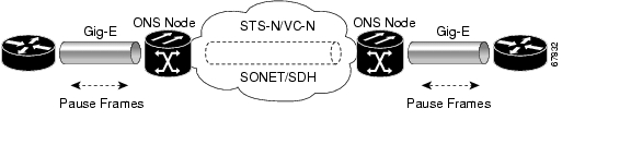
Figure 21-1 shows a G-Series application. In this example, data traffic from the Gigabit Ethernet port of a high-end router travels across the ONS node's point-to-point circuit to the Gigabit Ethernet port of another high-end router.
Figure 21-1 Data Traffic on a G-Series Point-to-Point Circuit
The G-Series cards carry any Layer 3 protocol that can be encapsulated and transported over Gigabit Ethernet, such as IP or IPX. The data is transmitted on the Gigabit Ethernet fiber into the standard Cisco Gigabit Interface Converter (GBIC) on an ONS 15454 or ONS 15454 SDH G-Series card or into the standard Small Form-factor Pluggable (SFP) modules on an ONS 15327 G-Series card. The G-Series card transparently maps Ethernet frames into the SONET/SDH payload by multiplexing the payload onto an OC-N/STM-N card. When the payload reaches the destination node, the process is reversed and the data is transmitted from the standard Cisco GBIC or SFP in the destination G-Series card onto the Gigabit Ethernet fiber.
The G-Series cards discard certain types of erroneous Ethernet frames rather than transport them over SONET/SDH. Erroneous Ethernet frames include corrupted frames with cycle redundancy check (CRC) errors and under-sized frames that do not conform to the minimum 64-byte length Ethernet standard. The G-Series cards forward valid frames unmodified over the SONET/SDH network. Information in the headers is not affected by the encapsulation and transport. For example, packets with formats that include IEEE 802.1Q information will travel through the process unaffected.
IEEE 802.3z Flow Control and Frame Buffering
The G-Series supports IEEE 802.3z flow control and frame buffering to reduce data traffic congestion. To prevent over-subscription, 512 KB of buffer memory is available for the receive and transmit channels on each port. When the buffer memory on the Ethernet port nears capacity, the G-Series uses IEEE 802.3z flow control to transmit a pause frame to the source at the opposite end of the Gigabit Ethernet connection.
The pause frame instructs the source to stop sending packets for a specific period of time. The sending station waits the requested amount of time before sending more data. Figure 21-1 illustrates pause frames being sent and received by G-Series cards and attached switches.
The G-Series cards have symmetric flow control. Symmetric flow control allows the G-Series cards to respond to pause frames sent from external devices and to send pause frames to external devices. Prior to Software R4.0, flow control on the G-Series cards was asymmetric, meaning that the cards sent pause frames and discarded received pause frames.
Software Release 5.0 and later features separate CTC provisioning of autonegotiation and flow control. A failed autonegotiation results in a link down.
When both autonegotiation and flow control are enabled, the G-Series card proposes symmetrical flow control to the attached Ethernet device. Flow control may be used or not depending on the result of the autonegotiation.
If autonegotiation is enabled but flow control is disabled, then the G-Series proposes no flow control during the autonegotiation. This negotiation succeeds only if the attached device agrees to no flow control.
If autonegotiation is disabled, then the attached device's provisioning is ignored. The G-Series card's flow control is enabled or disabled based solely on the G-Series card's provisioning.
This flow-control mechanism matches the sending and receiving device throughput to that of the bandwidth of the STS/VC circuit. For example, a router might transmit to the Gigabit Ethernet port on the G-Series card. This particular data rate might occasionally exceed 622 Mbps, but the SONET circuit assigned to the G-Series port might be only STS-12c (622 Mbps). In this example, the ONS 15454 sends out a pause frame and requests that the router delay its transmission for a certain period of time. With flow control and a substantial per-port buffering capability, a private line service provisioned at less than full line rate capacity (STS-24c) is efficient because frame loss can be controlled to a large extent. The same concept applies to the ONS 15454 SDH or ONS 15327.
The G-Series cards have flow control threshold provisioning, which allows a user to select one of three watermark (buffer size) settings: default, low latency, or custom. Default is the best setting for general use and was the only setting available prior to Software R4.1. Low latency is good for sub-rate applications, such as voice-over-IP (VoIP) over an STS-1. For attached devices with insufficient buffering, best effort traffic, or long access line lengths, set the G-Series to a higher latency.
The custom setting allows you to specify an exact buffer size threshold for Flow Ctrl Lo and Flow Ctrl Hi. The flow control high setting is the watermark for sending the Pause On frame to the attached Ethernet device; this frame signals the device to temporarily stop transmitting. The flow control low setting is the watermark for sending the Pause Off frame, which signals the device to resume transmitting. With a G-Series card, you can only enable flow control on a port if autonegotiation is enabled on the device attached to that port.
Note
Gigabit EtherChannel/IEEE 802.3ad Link Aggregation
The G-Series supports all forms of link aggregation technologies including GEC, which is a Cisco proprietary standard, and the IEEE 802.3ad standard. The end-to-end link integrity feature of the G-Series allows a circuit to emulate an Ethernet link. This allows all flavors of Layer 2 and Layer 3 rerouting to work correctly with the G-Series. Figure 21-2 illustrates G-Series GEC support.
Figure 21-2 G-Series Gigabit EtherChannel (GEC) Support
Although the G-Series cards do not actively run GEC, they support the end-to-end GEC functionality of attached Ethernet devices. If two Ethernet devices running GEC connect through G-Series cards to an ONS network, the ONS SONET/SDH side network is transparent to the EtherChannel devices. The EtherChannel devices operate as if they are directly connected to each other. Any combination of G-Series parallel circuit sizes can be used to support GEC throughput.
GEC provides line-level active redundancy and protection (1:1) for attached Ethernet equipment. It can also bundle parallel G-Series data links together to provide more aggregated bandwidth. Spanning Tree Protocol (STP) operates as if the bundled links are one link and permits GEC to utilize these multiple parallel paths. Without GEC, STP permits only a single nonblocked path. GEC can also provide G-Series card-level protection or redundancy because it can support a group of ports on different cards (or different nodes) so that if one port or card has a failure, traffic is rerouted over the other port or card.
The end-to-end Ethernet link integrity feature can be used in combination with Gigabit EtherChannel (GEC) capability on attached devices. The combination provides an Ethernet traffic restoration scheme that has a faster response time than alternate techniques such as spanning tree rerouting, yet is more bandwidth efficient because spare bandwidth does not need to be reserved.
Ethernet Link Integrity Support
The G-Series supports end-to-end Ethernet link integrity ( Figure 21-3). This capability is integral to providing an Ethernet private line service and correct operation of Layer 2 and Layer 3 protocols on the attached Ethernet devices. End-to-end Ethernet link integrity essentially means that if any part of the end-to-end path fails, the entire path fails. Failure of the entire path is ensured by turning off the transmit lasers at each end of the path. The attached Ethernet devices recognize the disabled transmit laser as a loss of carrier and consequently an inactive link.
Figure 21-3 End-to-End Ethernet Link Integrity Support
Note
As shown in Figure 21-3, a failure at any point of the path causes the G-Series card at each end to disable its Tx transmit laser, which causes the devices at both ends to detect a link down. If one of the Ethernet ports is administratively disabled or set in loopback mode, the port is considered a "failure" for the purposes of end-to-end link integrity because the end-to-end Ethernet path is unavailable. The port "failure" also disables both ends of the path.
Enhanced State Model for Gigabit Ethernet Ports
For Release 5.0 and later, the G-Series supports the Enhanced State Model (ESM) for the Gigabit Ethernet ports, as well as for the SONET/SDH circuit. For more information on ESM, see the "Enhanced State Model" appendix in the ONS 15454 SONET Reference Manual, ONS 15327 SONET Reference Manual or ONS 15454 SDH Reference Manual.
The Gigabit Ethernet ports can be set to the ESM service states including the automatic in-service administrative state (IS, AINS). IS, AINS initially puts the port in the out of service automatic, automatic in-service (OOS-AU, AINS) state. In this service state, alarm reporting is suppressed, but traffic is carried and loopbacks are allowed. After the soak period passes, the port changes to in-service, not reported (IS-NR). Raised fault conditions, whether their alarms are reported or not, can be retrieved on the CTC Conditions tab or by using the TL1 RTRV-COND command.
Two Ethernet port alarms/conditions, CARLOSS and TPTFAIL, can prevent the port from going into service. This occurs even though alarms are suppressed when a G-Series circuit is provisioned with the Gigabit Ethernet ports set to IS, AINS state. Because the G-Series link integrity function is active and ensures that the Tx transmit lasers at either end are not enabled until all SONET and Ethernet errors along the path are cleared. As long as the link integrity function keeps the end-to-end path down both ports will have at least one of the two conditions needed to suppress the AINS to IS transition so the ports will remain in the AINS state with alarms suppressed.
ESM also applies to the SONET/SDH circuits of the G-Series card. If the SONET/SDH circuit had been setup in IS, AINS state and the Ethernet error occurs before the circuit transitions to IS, then link integrity will also prevent the circuit transition to the IS state until the Ethernet port errors are cleared at both ends. Service state will be OOS-AU,AINS as long as the admin state is IS,AINS. Once there are no Ethernet or SONET errors link integrity enables the Gigabit Ethernet TX transmit lasers at each end. Simultaneously, the AINS countdown begins as normal. If no additional conditions occur during the time period each port transitions to the IS, NR state. During the AINS countdown the soak time remaining is available in CTC and TL1. The AINS soaking logic restarts from the beginning if a condition re-appears during the soak period.
A SONET/SDH circuit provisioned in the IS, AINS state remains in the initial OOS state until the Gigabit Ethernet ports on either end of the circuit transition to to the IS, NR state. The SONET/SDH circuit transports Ethernet traffic and count statistics when link integrity turns on the Gigabit Ethernet port Tx transmit lasers, regardless of whether this AINS to IS transition is complete.
G-Series Circuit Configurations
This section explains G-Series point-to-point circuits and manual cross-connects. Ethernet manual cross-connects allow you to bridge non-ONS SONET/SDH network segments.
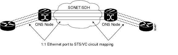
G-Series Point-to-Point Ethernet Circuits
G-Series cards support point-to-point circuit configurations ( Figure 21-4). Circuits are configured through CTC in the same manner as SONET or SDH line cards. G-Series cards support ESM for circuit service states.
On the ONS 15454 and ONS 15327, provisionable SONET circuit sizes are STS 1, STS 3c, STS 6c, STS 9c, STS 12c, STS 24c, and STS 48c. On the ONS 15454 SDH, provisionable SDH circuits are VC4, VC4-2c, VC4-3c, VC4-4c, VC4-8c, and VC4-16c. Each Ethernet port maps to a unique STS/VC circuit on the G-Series card.
Figure 21-4 G-Series Point-to-Point Circuit
The G-Series supports any combination of up to four circuits from the list of valid circuit sizes; however, the circuit sizes can add up to no more than 48 STSs or 16 VC4s.
Due to hardware constraints, the card imposes an additional restriction on the combinations of circuits that can be dropped onto a G-Series card. These restrictions are transparently enforced by the node, and you do not need to keep track of restricted circuit combinations.
When a single STS-24c/VC4-8c terminates on a card, the remaining circuits on that card can be another single STS-24c/VC4-8c or any combination of circuits of STS-12c/VC4-4c size or less that adds up to no more than 12 STSs or 4 VC4s (that is, a total of 36 STSs or 12 VC4s on the card).
If STS-24c/VC4-8c circuits are not being dropped on the card, the full bandwidth can be used with no restrictions (for example, using either a single STS-48c/VC4-16c or four STS-12c/VC4-4c circuits).
Because the STS-24c/VC4-8c restriction applies only when a single STS-24c/VC4-8c circuit is dropped; this restriction's impact can be minimized. Group the STS-24c/VC4-8c circuits together on a card separate from circuits of other sizes. The grouped circuits can be dropped on other G-Series cards.
Note
Caution
G-Series Manual Cross-Connects
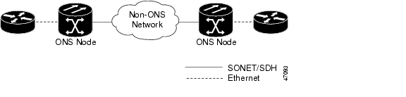
ONS nodes require end-to-end CTC visibility between nodes for normal provisioning of Ethernet circuits. When other vendors' equipment sits between ONS nodes, Simple Network Management Protocol/Target Identifier Address Resolution Protocol (OSI/TARP)-based equipment does not allow tunneling of the ONS node TCP/IP-based data communications channel (DCC). To circumvent inconsistent DCCs, the Ethernet circuit must be manually cross connected to an STS/VC channel using the non-ONS network. Manual cross-connects allow an Ethernet circuit to run from ONS node to ONS node while utilizing the non-ONS network ( Figure 21-5).
Note
Figure 21-5 G-Series Manual Cross-Connects
G-Series Gigabit Ethernet Transponder Mode
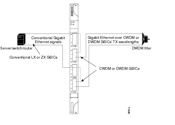
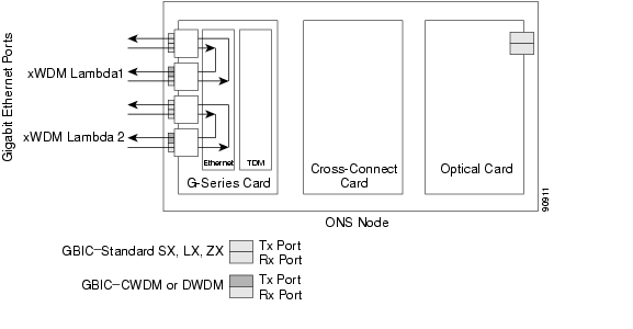
The ONS 15454 and ONS 15454 SDH G-Series cards can be configured as transponders. ONS 15327 G-Series cards cannot be configured as transponders. Transponder mode can be used with any G-Series-supported GBIC (SX, LX, ZX, coarse wavelength division multiplexing [CWDM], or dense wavelength division multiplexing [DWDM]). Figure 21-6 shows a card level overview of a transponder mode application.
Figure 21-6 Card Level Overview of G-Series One-Port Transponder Mode Application
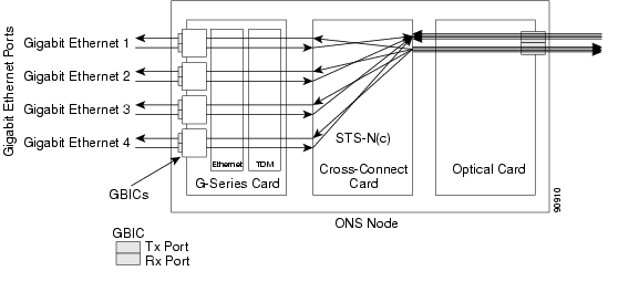
A G-Series card configured as a transponder operates quite differently than a G-Series card configured for SONET/SDH. In SONET/SDH configurations, the G-Series card receives and transmits Gigabit Ethernet traffic out the Ethernet ports and GBICs on the front of the card. This Ethernet traffic is multiplexed on and off the SONET/SDH network through the cross-connect card and the optical card ( Figure 21-7).
Figure 21-7 G-Series in Default SONET/SDH Mode
In transponder mode, the G-Series Ethernet traffic never comes into contact with the cross-connect card or the SONET/SDH network, but stays internal to the G-Series card and is routed back to a GBIC on that card ( Figure 21-8).
Figure 21-8 G-Series Card in Transponder Mode (Two-Port Bidirectional)
A G-Series card can be configured either for transponder mode or as the SONET/SDH default. When any port is provisioned in transponder mode, the card is in transponder mode and no SONET/SDH circuits can be configured until every port on the card goes back to SONET/SDH mode. To provision G-Series ports for transponder mode, refer to the Cisco ONS 15454 Procedure Guide or the Cisco ONS 15454 SDH Procedure Guide.
All SONET/SDH circuits must be deleted before a G-Series card can be configured in transponder mode. An ONS 15454 or ONS 15454 SDH can host the G-Series card configured in transponder mode in any or all of the 12 traffic slots and supports a maximum of 24 bidirectional or 48 unidirectional lambdas.
A G-Series card configured as a transponder can be in one of three modes:
•
•
•
Two-Port Bidirectional Transponder Mode
Two-port bidirectional transponder mode maps the transmitted and received Ethernet frames of one G-Series card port into the transmitted and received Ethernet frames of another port ( Figure 21-8). Transponder bidirectional port mapping can be done from any port to any other port on the same card.
One-Port Bidirectional Transponder Mode
One-port bidirectional transponder mode maps the Ethernet frames received at a port out the transmitter of the same port ( Figure 21-9). This mode is similar to two-port bidirectional transponder mode except that a port is mapped only to itself instead of to another port. Although the data path of the one-port bidirectional transponder mode is identical to that of a facility loopback, the transponder mode is not a maintenance mode and does not suppress non-SONET/SDH alarms, such as loss of carrier (CARLOSS).
This mode can be used for intermediate DWDM signal regeneration and to take advantage of the wide band capability of the CWDM and DWDM GBICs. This allows the node to receive on multiple wavelengths but transmit on a fixed wavelength.
Figure 21-9 One-Port Bidirectional Transponder Mode
Two-Port Unidirectional Transponder Mode
Ethernet frames received at one port's receiver will be transmitted out the transmitter of another port. This mode is similar to two-port bidirectional transponder mode except only one direction is used ( Figure 21-10). One port has to be provisioned as unidirectional transmit only and the other port as unidirectional receive. The port configured as unidirectional transmit ignores any lack of signal on the receive port, so the receive port fiber does not need not be connected. The port configured as unidirectional receive does not turn on the transmit laser, so the transmit port fiber does not need to be connected.
This mode can be used when only one direction needs to be transmitted over CWDM/DWDM, for example, certain video on demand (VoD) applications.
Figure 21-10 Two-Port Unidirectional Transponder
G-Series Transponder Mode Characteristics
The operation of a G-Series card in transponder mode differs from a G-Series card in SONET/SDH mode in several ways:
•
•
•
•
•
•
•
•
•
Note
The operation of a G-Series card in transponder mode is also similar to the operation of a G-Series card in SONET/SDH mode:
•
•
•
•
•
E-Series Application
The ONS 15454, ONS 15454 SDH and ONS 15327 all support E-Series cards. E-Series cards include the E100T-12/E100T-G and the E1000-2/E1000-2-G on the ONS 15454 and ONS 15454 SDH. The E100T-G is the functional equivalent of the earlier E100T-12. The E1000-2-G is the functional equivalent of the earlier E1000-2. An ONS 15454 using XC10G cards requires the G versions (E100T-G or E1000-2-G) of the E-Series Ethernet cards. An ONS 15454 or ONS 15454 SDH supports a maximum of ten E-Series cards. You can insert E-Series Ethernet cards in any multipurpose slot.
The ONS 15327 E-Series card is the E10/100-4. This is the only E-Series card that supports LEX encapsulation configuration, which allows interoperability with ML-Series cards, for more information see Chapter 20, "POS on ONS Ethernet Cards."
Note
E-Series Modes
An E-Series card operates in one of three modes: multicard EtherSwitch group, single-card EtherSwitch, or port-mapped. E-Series cards in multicard EtherSwitch group or single-card EtherSwitch mode support Layer 2 features, including virtual local area networks (VLANs), IEEE 802.1Q, STP, and IEEE 802.1D. Port-mapped mode configures the E-Series to operate as a straight mapper card and does not support these Layer 2 features. Within a node containing multiple E-Series cards, each E-Series card can operate in any of the three separate modes. At the Ethernet card view in CTC, click the Provisioning > Ether Card tabs to reveal the card modes.
Note
E-Series Multicard EtherSwitch Group
Multicard EtherSwitch group provisions two or more Ethernet cards to act as a single Layer 2 switch. Figure 21-11 illustrates a multicard EtherSwitch configuration. Multicard EtherSwitch limits bandwidth to STS-6c of bandwidth between two Ethernet circuit points for the ONS 15454 or ONS 15454 SDH E-Series cards and STS-3c of bandwidth between ONS 15327 E-Series cards, but allows you to add nodes and cards and make a shared packet ring.
Figure 21-11 Multicard EtherSwitch Configuration
Caution
E-Series Single-Card EtherSwitch
On all E-Series cards, Single-card EtherSwitch allows each Ethernet card to remain a single switching entity within the ONS node. Figure 21-12 illustrates a single-card EtherSwitch configuration.
Figure 21-12 Single-Card EtherSwitch Configuration
Port-Mapped (Linear Mapper)
Port-mapped mode, also referred to as linear mapper, configures the E-Series card to map a specific E-Series Ethernet port to one of the card's specific STS/VC circuits ( Figure 21-13). Port-mapped mode ensures that Layer 1 transport has low latency for unicast, multicast, and mixed traffic. Ethernet and Fast Ethernet on the E100T-G or E10/100-4 card operate at line-rate speed. Gigabit Ethernet transport is limited to a maximum of 600 Mbps because the E1000-2-G card has a maximum bandwidth of STS-12c/VC4-4c. Ethernet frame sizes up to 1522 bytes are also supported, which allow transport of IEEE 802.1Q tagged frames. The larger maximum frame size of Q-in-Q frames (IEEE 802.1Q in IEEE 802.1Q wrapped frames) is not supported.
Figure 21-13 E-Series Mapping Ethernet Ports to STS/VC Circuits
Port-mapped mode disables Layer 2 functions supported by the E-Series in single-card and multicard mode, including STP, VLANs, and MAC address learning. It significantly reduces the service-affecting time for cross-connect and TCC2/TCC2P card switches.
Port-mapped mode does not support VLANs in the same manner as multicard and single-card mode. The ports of E-Series cards in multicard and single-card mode can join specific VLANs. E-Series cards in port-mapped mode do not have this Layer 2 capability and only transparently transport external VLANs over the mapped connection between ports. An E-Series card in port-mapped mode does not inspect the tag of the transported VLAN, so a VLAN range of 1 through 4096 can be transported in port-mapped mode.
Port-mapped mode does not perform any inspection or validation of the Ethernet frame header. The Ethernet CRC is validated, and any frame with an invalid Ethernet CRC is discarded.
Port-mapped mode also allows the creation of STS/VC circuits between any two E-Series cards, including the E100T-G, E1000-2-G, and the E10/100-4 (the ONS 15327 E-Series card). Port-mapped mode does not allow ONS 15454 E-Series cards to connect to the ML-Series or G-Series cards, but does allow an ONS 15327 E10/100-4 card provisioned with LEX encapsulation to connect to the ML-Series or G-Series cards.
Available Circuit Sizes For E-Series Modes
Table 21-1 shows the circuit sizes available for E-Series modes on the ONS 15454, ONS 15454 SDH, and ONS 15327.
Available Total Bandwidth For E-Series Modes
Table 21-1 shows the total bandwidth available for E-Series modes on the ONS 15454, ONS 15454 SDH, and ONS 15327.
E-Series IEEE 802.3z Flow Control
The E100T-G or E10/100-4 (operating in any mode) and the E1000-2-G (operating port-mapped mode) support IEEE 802.3z symmetrical flow control and propose symmetric flow control when autonegotiating with attached Ethernet devices. For flow control to operate, both the E-Series port and the attached Ethernet device must be set to autonegotiation (AUTO) mode. The attached Ethernet device might also need to have flow control enabled. The flow-control mechanism allows the E-Series to respond to pause frames sent from external devices and send pause frames to external devices.
For the E100T-G or E10/100-4 (operating in any mode) and the E1000-2-G (operating port-mapped mode), flow control matches the sending and receiving device throughput to that of the bandwidth of the STS circuit. This same concept applies to the ONS 15454, ONS 15454 SDH and ONS 15327. For example, a router might transmit to the Gigabit Ethernet port on the E-Series in port-mapped mode. The data rate transmitted by the router might occasionally exceed 622 Mbps, but the ONS 15454 circuit assigned to the E-Series port in port-mapped mode is a maximum of STS-12c (622.08 Mbps). In this scenario, the ONS 15454 sends out a pause frame and requests that the router delay its transmission for a certain period of time.
Note
E-Series VLAN Support
You can provision E-Series VLANs with the CTC software. Specific sets of ports define the broadcast domain for the ONS node. The definition of VLAN ports includes all Ethernet and packet-switched SONET/SDH port types. All VLAN IP address discovery, flooding, and forwarding is limited to these ports.
Caution
The IEEE 802.1Q-based VLAN mechanism provides logical isolation of subscriber LAN traffic over a common SONET/SDH transport infrastructure. Each subscriber has an Ethernet port at each site, and each subscriber is assigned to a VLAN. Although the subscriber's VLAN data flows over shared circuits, the service appears to the subscriber as a private data transport.
Note
The number of VLANs used by circuits and the total number of VLANs available for use appears in CTC on the VLAN counter ( Figure 21-14).
Figure 21-14 Edit Circuit Dialog Box Featuring Available VLANs
E-Series Q-Tagging (IEEE 802.1Q)
E-Series cards in single-card and multicard mode support IEEE 802.1Q. IEEE 802.1Q allows the same physical port to host multiple IEEE 802.1Q VLANs. Each IEEE 802.1Q VLAN represents a different logical network. E-Series cards in port-mapped mode transport IEEE 802.1Q tags (Q-tags), but do not remove or add these tags.
The ONS node works with Ethernet devices that support IEEE 802.1Q and those that do not support IEEE 802.1Q. If a device attached to an E-Series Ethernet port does not support IEEE 802.1Q, the ONS node uses Q-tags internally only. The ONS node associates these Q-tags with specific ports.
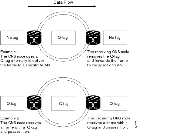
With Ethernet devices that do not support IEEE 802.1Q, the ONS node takes non-tagged Ethernet frames that enter the ONS network and uses a Q-tag to assign the packet to the VLAN associated with the ONS network's ingress port. The receiving ONS node removes the Q-tag when the frame leaves the ONS network (to prevent older Ethernet equipment from incorrectly identifying the IEEE 802.1Q packet as an illegal frame). The ingress and egress ports on the ONS network must be set to Untag for the removal to occur. Untag is the default setting for ONS ports. Example 1 in Figure 21-15 illustrates Q-tag use only within an ONS network.
Figure 21-15 Q-tag Moving Through VLAN
The ONS node uses the Q-tag attached by the external Ethernet devices that support IEEE 802.1Q. Packets enter the ONS network with an existing Q-tag; the ONS node uses this same Q-tag to forward the packet within the ONS network and leaves the Q-tag attached when the packet leaves the ONS network. The entry and egress ports on the ONS network must be set to Tagged for this process to occur. Example 2 in Figure 21-15 illustrates the handling of packets that both enter and exit the ONS network with a Q-tag.
For more information about setting ports to Tagged and Untag, refer to the Cisco ONS 15454 Procedure Guide, the Cisco ONS 15454 SDH Procedure Guide, or the Cisco ONS 15327 Procedure Guide.
Caution
E-Series Priority Queuing (IEEE 802.1Q)
Networks without priority queuing handle all packets on a first-in-first-out (FIFO) basis. Priority queuing reduces the impact of network congestion by mapping Ethernet traffic to different priority levels. The E-Series card supports priority queuing. The E-Series card maps the eight priorities specified in IEEE 802.1Q to two queues, low priority and high priority ( Table 21-3).
Table 21-3 Priority Queuing
0,1,2,3
Low
30%
4,5,6,7
High
70%
Q-tags carry priority queuing information through the network ( Figure 21-16).
Figure 21-16 Priority Queuing Process
The ONS node uses a "leaky bucket" algorithm to establish a weighted priority. A weighted priority, as opposed to a strict priority, gives high-priority packets greater access to bandwidth, but does not totally preempt low-priority packets. During periods of network congestion, about 70 percent of bandwidth goes to the high-priority queue and the remaining 30 percent goes to the low-priority queue. A network that is too congested will drop packets.
Note
Note
E-Series Spanning Tree (IEEE 802.1D)
The E-Series operates IEEE 802.1D Spanning Tree Protocol (STP). The E-Series card supports common STPs on a per-circuit basis up to a total of eight STP instances. It does not support per-VLAN STP. In single-card mode, STP can be disabled or enabled on a per-circuit basis during circuit creation. Disabling STP will preserve the number of available STP instances.
STP operates over all packet-switched ports including Ethernet and OC-N/STM-N ports. On Ethernet ports, STP is enabled by default but can be disabled. A user can also disable or enable STP on a circuit-by-circuit basis on Ethernet cards configured as single-card EtherSwitch (unstitched) in a point-to-point configuration. However, turning off STP protection on a circuit-by-circuit basis means that the SONET/SDH system is not protecting the Ethernet traffic on this circuit, and the Ethernet traffic must be protected by another mechanism in the Ethernet network. On OC-N/STM-N interface ports, the ONS node activates STP by default, and STP cannot be disabled.
The Ethernet card can enable STP on the Ethernet ports to create redundant paths to the attached Ethernet equipment. STP connects cards so that both equipment and facilities are protected against failure.
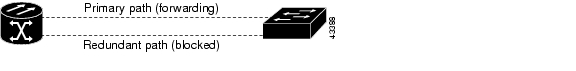
STP detects and eliminates network loops. When STP detects multiple paths between any two network hosts, STP blocks ports until only one path exists between any two network hosts ( Figure 21-17). The single path eliminates possible bridge loops. This is crucial for shared packet rings, which naturally include a loop.
Figure 21-17 STP Blocked Path
To remove loops, STP defines a tree that spans all the switches in an extended network. STP forces certain redundant data paths into a standby (blocked) state. If one network segment in the STP becomes unreachable, the STP algorithm reconfigures the STP topology and reactivates the blocked path to reestablish the link. STP operation is transparent to end stations, which do not discriminate between connections to a single LAN segment or to a switched LAN with multiple segments. The ONS node supports one STP instance per circuit and a maximum of eight STP instances per ONS node.
The Circuit window shows forwarding spans and blocked spans on the spanning tree map ( Figure 21-18).
Figure 21-18 Spanning Tree Map on Circuit Window
Note
Caution
Note
E-Series Multi-Instance Spanning Tree and VLANs
The ONS node can operate multiple instances of STP to support VLANs in a looped topology. You can dedicate separate circuits across the SONET/SDH ring for different VLAN groups. Each circuit runs its own STP to maintain VLAN connectivity in a multi-ring environment.
Spanning Tree on a Circuit-by-Circuit Basis
You can also disable or enable STP on a circuit-by-circuit basis on single-card EtherSwitch E-Series cards in a point-to-point configuration. This feature allows customers to mix spanning tree protected circuits with unprotected circuits on the same card. It also allows two single-card EtherSwitch E-Series cards on the same node to form an intranode circuit.
E-Series Spanning Tree Parameters
Default STP parameters are appropriate for most situations ( Table 21-4). Contact the Cisco Technical Assistance Center (Cisco TAC) before you change the default STP parameters. See the "Obtaining Documentation, Obtaining Support, and Security Guidelines" section on page xxxiii for information on how to contact Cisco TAC.
E-Series Spanning Tree Configuration
To view the spanning tree configuration, at the node view click the Provisioning > Etherbridge > Spanning Trees tabs ( Table 21-5).
E-Series Circuit Configurations
E-Series Ethernet circuits can link ONS nodes through point-to-point (straight), shared packet ring, or hub-and-spoke configurations. Two nodes usually connect with a point-to-point configuration. More than two nodes usually connect with a shared packet ring configuration or a hub-and-spoke configuration. Ethernet manual cross-connects allow you to cross connect individual Ethernet circuits to an STS/VC channel on the ONS node optical interface and also to bridge non-ONS SONET/SDH network segments. To configure E-Series circuits, refer to the Cisco ONS 15454 Procedure Guide, the Cisco ONS 15454 SDH Procedure Guide, or the Cisco ONS 15327 Procedure Guide.
E-Series Circuit Protection
Different combinations of E-Series circuit configurations and SONET/SDH network topologies offer different levels of E-Series circuit protection. Table 21-6 details the available protection.
Note
Note
E-Series Point-to-Point Ethernet Circuits
The ONS nodes can set up a point-to-point (straight) Ethernet circuit as single-card, port-mapped, or multicard circuit ( Figure 21-19).
Figure 21-19 Multicard EtherSwitch Point-to-Point Circuit
Single-card EtherSwitch and port-mapped modes provide a full STS-12c of bandwidth between two Ethernet circuit endpoints ( Figure 21-20).
Figure 21-20 Single-Card EtherSwitch or Port-Mapped Point-to-Point Circuit
Note
E-Series Shared Packet Ring Ethernet Circuits
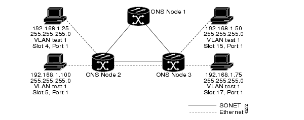
A shared packet ring allows additional nodes (besides the source and destination nodes) access to an Ethernet STS circuit. The E-Series card ports on the additional nodes can share the circuit's VLAN and bandwidth. Figure 21-21 illustrates a shared packet ring. Your network architecture might differ from the example.
Figure 21-21 Shared Packet Ring Ethernet Circuit
E-Series Hub-and-Spoke Ethernet Circuit Provisioning
The hub-and-spoke configuration connects point-to-point circuits (the spokes) to an aggregation point (the hub). In many cases, the hub links to a high-speed connection and the spokes are Ethernet cards. Figure 21-22 illustrates a hub-and-spoke ring. Your network architecture might differ from the example.
Figure 21-22 Hub-and-Spoke Ethernet Circuit
E-Series Ethernet Manual Cross-Connects
ONS nodes require end-to-end CTC visibility between nodes for normal provisioning of Ethernet circuits. When other vendors' equipment sits between ONS nodes, OSI/TARP-based equipment does not allow tunneling of the ONS node TCP/IP-based DCC. To circumvent this inconsistent DCC, the Ethernet circuit must be manually cross connected to an STS channel using the non-ONS network. The manual cross-connect allows an Ethernet circuit to run from ONS node to ONS node utilizing the non-ONS network.
Note
Remote Monitoring Specification Alarm Thresholds
The ONS nodes features remote monitoring (RMON) that allows network operators to monitor the health of the network with a network management system (NMS).
One of the ONS node's RMON MIBs is the Alarm group, which consists of the alarmTable. An NMS uses the alarmTable to find the alarm-causing thresholds for network performance. The thresholds apply to the current 15-minute interval and the current 24-hour interval. RMON monitors several variables, such as Ethernet collisions, and triggers an event when the variable crosses a threshold during that time interval. For example, if a threshold is set at 1000 collisions and 1001 collisions occur during the 15-minute interval, an event triggers. CTC allows you to provision these thresholds for Ethernet statistics.
For Ethernet RMON alarm threshold procedures, refer to the Cisco ONS 15454 Troubleshooting Guide, Cisco ONS 15454 Troubleshooting Guide or Cisco ONS 15327 Troubleshooting Guide.
![]()
![]()
![]()
![]()
![]()
![]()
![]()
![]()
Posted: Tue Oct 30 11:41:34 PDT 2007
All contents are Copyright © 1992--2007 Cisco Systems, Inc. All rights reserved.
Important Notices and Privacy Statement.