|
|

Table Of Contents
System Planning and Engineering
Shelf Assembly Configuration Rules
Card and Hardware Compatibility
Electrical Interface Adapters (EIAs)
Operations Systems (OSS) LAN Connections
Cable Routing and Management Overview
Electrical Cable Management Using the Optional Tie-Down Bar
Standoffs and Rear Plastic Cover
Timing and Synchronization Features
Synchronization Status Messaging
Using the ONS 15454 Without SSM
Network Synchronization Design
Synchronization Failure Switching
Synchronization Switching Time
Card Protection Configurations
Transponder and Muxponder Card Protection
In-Service Low-Density to High-Density Upgrades
Upgrade Low-Density Electrical Cards to High-Density Electrical Cards
System Planning and Engineering
Note
The terms "Unidirectional Path Switched Ring" and "UPSR" may appear in Cisco literature. These terms do not refer to using Cisco ONS 15xxx products in a unidirectional path switched ring configuration. Rather, these terms, as well as "Path Protected Mesh Network" and "PPMN," refer generally to Cisco's path protection feature, which may be used in any topological network configuration. Cisco does not recommend using its path protection feature in any particular topological network configuration.
This chapter describes the basic planning and engineering information required to configure an ONS 15454 for deployment.
The following topics are covered in this chapter:
•
•
•
•
•
Note
Shelf Configurations
The ONS 15454 is a flexible platform that can be deployed in three types of configurations; multiservice provisioning platform (MSPP), multiservice transport platform (MSTP) or Hybrid. Each of these configurations requires a minimum set of components to operate the system. The following tables outline the minimum required components necessary to operate an ONS 15454 node.
MSPP Configurations
Cisco ONS 15454 MSPP configurations provide efficient multiservice aggregation (multiplexing) to SONET transport. Table 7-1 outlines the minimum components needed to build a functional MSPP node.
An ONS 15454 MSPP node can be activated with only the above equipment. You will then need to select appropriate service interfaces, which can include optical cards, electrical cards (with appropriate electrical interface adapter [EIA] panels), Ethernet cards, and storage access networking (SAN) cards to meet the particular deployment application.
Point-to-Point Nodes
Point-to-point or 1+1 protected extensions are often used to interconnect SONET subnetworks. Examples include interconnection of two access networks and interconnection between interoffice rings. ONS 15454 nodes can be configured to provide 1+1 protected transport directly to end users when the fiber topology warrants point-to-point connection rather than ring connection.
Figure 7-1 shows two ONS 15454 nodes in a point-to-point configuration. Working traffic flows from Slot 5/Node 1 to Slot 5/Node 2. You create the protect path by placing Slot 6/Node 1 in 1+1 protection with Slot 6/Node 2.
Figure 7-1 Point-to-Point 1+1 Protection Configuration
Linear ADM Nodes
You can configure ONS 15454s as a line of add/drop multiplexers (ADMs) by configuring one set of OC-N cards as the working path and a second set as the protect path. Unlike rings, linear (point-to-point) ADMs require that the OC-N cards at each node be in 1+1 protection to ensure that a break to the working line is automatically routed to the protect line.
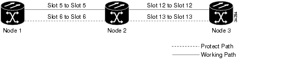
Figure 7-2 shows three ONS 15454 nodes in a linear ADM configuration. Working traffic flows from Slot 5/Node 1 to Slot 5/Node 2, and from Slot 12/Node 2 to Slot 12/Node 3. You create the protect path by placing Slot 6 in 1+1 protection with Slot 5 at Nodes 1 and 2, and Slot 12 in 1+1 protection with Slot 13 at Nodes 2 and 3.
Figure 7-2 Linear ADM Configuration
Path Protection Nodes
Path protection configurations provide duplicate fiber paths around the ring. Working traffic flows in one direction and protection traffic flows in the opposite direction. If a problem occurs with the working traffic path, the receiving node switches to the path coming from the opposite direction.
Path protection is the default ring configuration for the ONS 15454. CTC automates the path protection configuration on a circuit-by-circuit basis during the circuit provisioning process. If a path-protected circuit is not defined within a 1+1 or BLSR line protection scheme and path protection is available and specified, CTC uses path protection as the default.
A path protection circuit requires two DCC-provisioned optical spans per node. Path protection circuits can be created across these spans until their bandwidth is consumed.
Note
The span bandwidth consumed by a path protection circuit is two times the circuit bandwidth, because the circuit is duplicated. The cross-connection bandwidth consumed by a path protection circuit is three times the circuit bandwidth at the source and destination nodes only. The cross-connection bandwidth consumed by an intermediate node has a factor of one. The same STSs assigned to a circuit are used throughout the ring.
The path protection circuit limit is the sum of the optical bandwidth containing 10 section data communications channels (SDCCs) divided by two if you are using redundant TCC+ cards or 84 SDCCs divided by two if you are using redundant TCC2/TCC2P cards. The spans can be of any bandwidth from OC-3 to OC-192. The circuits can be of any size from VT1.5 to STS-192c.
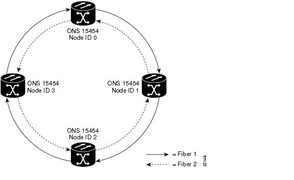
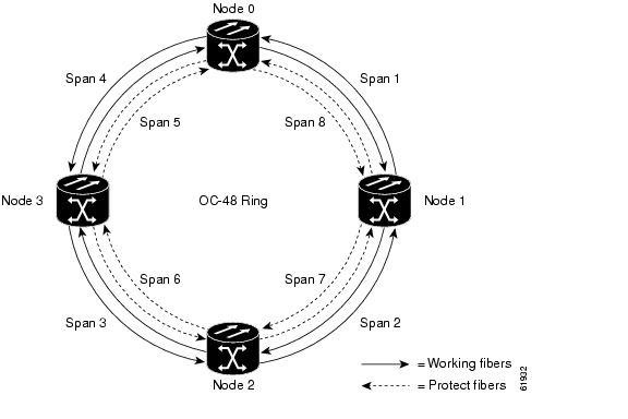
Figure 7-3 shows a basic OC-48 path protection configuration. If Node ID 0 sends a signal to Node ID 2, the working signal travels on the working traffic path through Node ID 1. The same signal is also sent on the protect traffic path through Node ID 3.
Figure 7-3 Basic OC-48 Path Protection Configuration
Path Protection Fiber Connections
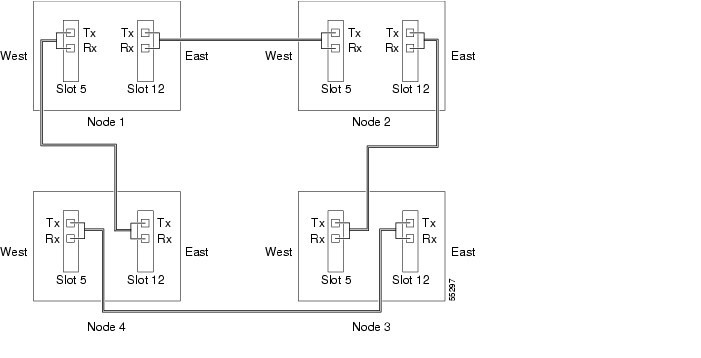
Plan your fiber connections and use the same plan for all path protection nodes. For example, make the east port the farthest slot to the right and the west port the farthest slot to the left. Plug fiber connected to an east port at one node into the west port on an adjacent node. Figure 7-4 shows fiber connections for a path protection with trunk cards in Slot 5 (west) and Slot 12 (east) at each of the nodes in the ring. Refer to the Cisco ONS 15454 Procedure Guide for fiber connection procedures.
Note
Figure 7-4 Connecting Fiber to a Four-Node Path Protection
For more information about path protection configurations, refer to Chapter 2 in this document.
Two-Fiber BLSR Nodes
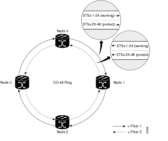
In two-fiber BLSR nodes, each fiber is divided into working and protect bandwidths. For example, in an OC-48 BLSR ( Figure 7-5), STSs 1 to 24 carry the working traffic, and STSs 25 to 48 are reserved for protection. Working traffic (STSs 1 to 24) travels in one direction on one fiber and in the opposite direction on the second fiber. STS bandwidth can be reused as traffic is added or dropped at various nodes. An ONS 15454 network can support up to 16 nodes in a BLSR.
Figure 7-5 Four-Node, Two-Fiber BLSR
The Cisco Transport Controller (CTC) circuit routing routines calculate the shortest path for circuits based on many factors, including user requirements, traffic patterns, and distance. For example, in Figure 7-5 circuits going from Node 0 to Node 1 typically travel on Fiber 1, unless that fiber is full, in which case circuits are routed on Fiber 2 through Node 3 and Node 2. Traffic from Node 0 to Node 2 (or Node 1 to Node 3) can be routed on either fiber, depending on circuit provisioning requirements and traffic loads.
The SONET K1, K2, and K3 bytes carry the information that governs BLSR protection switches. Each BLSR node monitors the K bytes to determine when to switch the SONET signal to an alternate physical path. The K bytes communicate failure conditions and actions taken between nodes in the ring.
If a break occurs on one fiber, working traffic targeted for a node beyond the break switches to the protect bandwidth on the second fiber. The traffic travels in a reverse direction on the protect bandwidth until it reaches its destination node. At that point, traffic is switched back to the working bandwidth.
Fiber Connections for Two-Fiber BLSR Nodes
Plan your fiber connections and use the same plan for all BLSR nodes. For example, make the east port the farthest slot to the right and the west port the farthest slot to the left. Plug fiber connected to an east port at one node into the west port on an adjacent node. Figure 7-6 shows fiber connections for a two-fiber BLSR with trunk cards in Slot 5 (west) and Slot 12 (east). Refer to the Cisco ONS 15454 Procedure Guide for fiber connection procedures.
Note
Figure 7-6 Connecting Fiber to a Four-Node, Two-Fiber BLSR
For more information on two-fiber BLSRs, refere to Chapter 2 in this document.
Four-Fiber BLSR Nodes
Four-fiber BLSRs double the bandwidth of two-fiber BLSRs. Because they allow span switching as well as ring switching, four-fiber BLSRs increase the reliability and flexibility of traffic protection. Two fibers are allocated for working traffic and two fibers for protection, as shown in Figure 7-7. To implement a four-fiber BLSR, you must install four OC-48, OC-48AS, or OC-192 cards at each BLSR node. Four-fiber BLSRs provide span and ring switching.
Figure 7-7 Four Node, Four-Fiber BLSR
Fiber Connections to a Four-Fiber BLSR Node
For four-fiber BLSRs, use the same east-west connection pattern for the working and protect fibers as you would for two-fiber BLSRs. Do not mix working and protect card connections. The BLSR does not function if working and protect cards are interconnected. Figure 7-8 shows fiber connections for a four-fiber BLSR. Slot 5 (west) and Slot 12 (east) carry the working traffic. Slot 6 (west) and Slot 13 (east) carry the protect traffic.
Figure 7-8 Connecting Fiber to a Four-Node, Four-Fiber BLSR
For more information on four-fiber BLSRs, refer to Chapter 2 in this document.
Subtended Rings
The ONS 15454 supports up to ten SONET SDCCs with TCC+ cards and 84 SONET SDCCs with TCC2/TCC2P cards. See Table 7-2 and Table 7-3 for the maximum number of rings supported per ONS 15454 node.
Table 7-2 ONS 15454 Rings with Redundant TCC+ Cards
2-Fiber BLSR
2
4-Fiber BLSR
1
Path protection
5
Table 7-3 ONS 15454 Rings with Redundant TCC2/TCC2P Cards
2-Fiber BLSR
5
4-Fiber BLSR
1
Path protection
42
Table 7-4 shows the combination of subtending ring configurations each ONS 15454 can support.
Subtending rings reduce the number of nodes and cards required and reduce external shelf-to-shelf cabling. Figure 7-9 shows multiple rings subtending from Node 1 inside the CO. Node 1 is part of an OC-192 BLSR. It has an OC-192 BLSR going into the primary shelf, three OC-12 subtending path protection configurations, and one 1+1 OC-48 drop to the subtending shelf (see Figure 7-10). The subtending shelf contains multiple OC-3 and DS-3 drops supporting various end users.
Figure 7-9 Multiple Subtending Rings
Figure 7-10 Node 1 Subtending Shelves
MSTP Configurations
MSTP nodes provide wavelength aggregation for DWDM transport. Table 7-5 and Table 7-6 outline the minimum components necessary, by ring and linear node types, to build a functional MSTP system.
Note
Each of the ONS 15454 MSTP node can be activated with only the above equipment. Depending upon your particular application, the system will require additional components, including optical services cards and additional optical filters. For additional informat regarding MSTP node types, refer to Chapter 4 in this document or the Cisco ONS 15454 DWDM Installation and Operations Guide.
Hybrid Configuration
The Hybrid configuration is a combination of the MSPP and MSTP functionality contained within a single network element. Each of these system configurations will be unique and will require a minimum of the following equipment outlined in Table 7-7.
Table 7-7 Minimum Hybrid Node Requirements
Shelf Assembly
1
Fan Tray Assembly
1
TCC2/TCC2P Card
2
Cross-connect Card
2
System Software License
1
Hybrid nodes may also include optical filters, amplifiers, optical service channel cards, multiservice interfaces, Transponders, Muxponders, or a combination of these components.
Shelf Assembly Configuration Rules
Each shelf assembly requires you to follow a minimal set of configuration rules for proper operation and performance. The main rules focus on selecting an assembly shelf and fan tray assembly, understanding ONS 15454 card slot assignments, and choosing the common control and cross-connect cards compatible with your software release.
The ONS 15454 shelf assembly, shown in Figure 7-11, is a very compact footprint with an integrated upper air ramp and fan tray slot enabling up to 4 shelves to be installed within a typical 7-foot high ANSI equipment rack, including room for a 1.75-inch high fuse and alarm panel. The shelf assembly supports rear mounted connections for redundant -48 VDC power inputs, LAN interfaces, timing inputs and outputs, and housekeeping alarms. The ONS 15454 shelf assembly provides flexibility through pluggable front access interface card slots for common control and service interface cards and flexible electrical signal termination capabilities through the rear mounted, pluggable electrical interface adapter (EIA) panels. The shelf assembly comes equipped with mounting hardware for installation in 19-inch or 23-inch ANSI compliant racks.
Figure 7-11 ONS 15454 Shelf Assembly
The physical and environmental specifications for both the ONS 15454-SA-ANSI and ONS 15454-SA-HD shelf is listed in Table 7-8.
For more information on the ONS 15454 assembly shelf, refer to "Shelf Assemblies" section in this document.
Shelf Assemblies
The latest version shelf assembly, model 15454-SA-HD, is the default shelf shipping for new installations since Software Release 4.6. This shelf assembly is backwards compatible to Release 4.0 installations. For installations prior to Release 4.6, select the shelf assembly from Table 7-9 that is compatible with the version of software you plan to use. The 15454-SA-HD, 15454-SA-ANSI, and 15454-SA-NEBS3E shelves meet NEBS Level 3 specifications for Type 2 and Type 4 equipment, which is intended for installation in restricted access areas.
System Release 3.1 introduced the 15454-SA-ANSI shelf assembly. This shelf has enhanced fiber management capabilities and is designed to support the 10Gb/s hardware, which includes the XC-10G cross-connect, OC48 any slot, and OC192 cards. This shelf is compatible with Software Release 4.6, but cannot support the high-density electrical cards.
Although the high density shelf became available with Release 4.6, it is not software dependant. The new 15454-SA-HD shelf incorporates additional DS-1, DS-3, and EC-1 interfaces that enable the ONS 15454 to support up to 224 DS-1s, 192 DS-3s and EC-1s, and 1:N protection. Except for these changes and new symbols identifying the high density card slots assignments, this new shelf is identical to the 15454-SA-ANSI shelf assembly. In order to support the additional electrical traffic, the 15454-SA-HD shelf must be equipped with new high density DS-1 and DS-3 plug-in cards and either the MiniBNC, UBIC-H, or UBIC-V electrical interface assemblies (EIAs). The 15454-SA-HD shelf is the standard shelf shipped for new installations starting with Release 4.6.
Fan-Tray Assemblies
Caution
The fan-tray assembly is located at the bottom of the ONS 15454 fan-tray assembly. The fan tray is a removable drawer that holds fans and fan-control circuitry for the ONS 15454. The front door can be left in place or removed before installing the fan-tray assembly. After you install the fan tray, you should only need to access it if a fan failure occurs or you need to replace or clean the fan-tray air filter.
The front of the fan-tray assembly has an LCD screen that provides slot and port-level information for all ONS 15454 card slots, including the number of Critical, Major, and Minor alarms. The LCD also tells you whether the software load is SONET or SDH and the software version number.
Release 4.0 and higher allows you to modify parameters and control the following displayed information:
•
•
•
You can also modify display parameters to prohibit configuration changes via the LCD display touch pad.
The fan-tray assembly features an air filter at the bottom of the tray that you can install and remove by hand. Remove and visually inspect this filter every 30 days and keep spare filters in stock. Refer to the Cisco ONS 15454 Troubleshooting Guide for information about cleaning and maintaining the fan-tray air filter.
There are presently two series of fan tray assemblies available for the ONS 15454: the FTA3-T high airflow assembly and the FTA2 standard airflow assembly. The FTA3-T should be used for all new installations and offers higher airflow capabilities required to support systems equipped with XC-10G cross-connect cards and is rated for industrial temperature installations (-40 to +65 Celsius). The FTA3-T employs a positive stop insertion pin to prevent the installation of the fan tray assembly into shelf assembly versions prior to the current ANSI offering. Use Table 7-10 to select the fan-tray assembly that is compatible with the version of shelf assembly you plan to use.
Power requirements for the FTA3-T and FTA2 fan-tray assemblies are listed in Table 7-11.
Table 7-11 Fan Tray Assembly Power Requirements
15454-FTA3-T
86.4
1.8
295
15454-FTA2
53
1.21
198
If one or more fans fail on the fan-tray assembly, replace the entire assembly. You cannot replace individual fans. The red Fan Fail LED on the front of the fan tray illuminates when one or more fans fail. For fan tray replacement instructions, refer to the Cisco ONS 15454 Troubleshooting Guide. The red Fan Fail LED clears after you install a working fan tray.
Air Filter
The ONS 15454 contains a reusable air filter; Model 15454-FTF2, that is installed either beneath the fan-tray assembly or in the optional external filter brackets. Earlier versions of the ONS 15454 used a disposable air filter that is installed beneath the fan-tray assembly only. However, the reusable air filter is backward compatible.
Card Slot Assignments
The shelf assembly has 17 card slots as shown in Figure 7-12.
Figure 7-12 Shelf Assembly Card Slots
The card slots are numbered sequentially from 1 to 17 with slot #1 starting at the far left. Each slot is also labeled with an ICON symbol that can be matched with a symbol on the card's faceplate. These symbols provide easy identification of card to slot compatibility. Five card slots, 7 - 11, are dedicated to system operations, also known as common cards, and twelve card slots, 1 - 6 and 12 - 17, are for multi-service interface cards. A further breakout is outlined below:
Slots 1 through 6 - Referred to the A-Side of the shelf assembly and are compatible with a wide variety of interface cards. Bandwidth supported per shelf slot is dependent upon the type of cross-connect card installed. In Figure 7-12, slots 1 through 4, are low-speed card slots and support up to STS-48 (2.49Gb/s) bandwidth. Slots 5 and 6, are considered high-speed slots and support up to STS-192 (10Gb/s) bandwidth. Multi-service interface cards can be operated in protected and unprotected pairs or groups.
Slots 7 and 11 - Support the system processors referred to as the Timing, Communications and Control (TCC) cards. The shelf assembly should be equipped with two TCC cards to enable full system redundancy. Cisco does not support operation of the ONS 15454 with only one TCC card.
Slots 8 and 10 - Support either the system Cross-connect cards or the Optical Service Channel (OSC) cards. For TDM switching, equip the shelf assembly with two cross-connect cards of matching variety, to allow for 1+1 redundant operation. OSC cards are deployed in MSTP configurations for each DWDM span terminating on the shelf.
Slot 9 - Supports the optional Alarm Interface Controller (AIC) card. This card provides environmental alarm inputs and output controls, orderwire, and user data channel (UDC) capabilities. It is not required for system operation.
Slots 12 through 17 - Referred to the B-Side of the shelf assembly and are compatible with a wide variety of interface cards. Bandwidth supported per shelf slot is dependent upon the type of cross-connect card installed. In Figure 7-12, slots 1 through 4, are low-speed card slots and supports up to STS-48 (2.49Gb/s) bandwidth. Slots 12 and 13, are high-speed slots and support up to STS-192 (10Gb/s) bandwidth. Multi-service interface cards can be operated in protected and unprotected pairs or groups.
Shelf Slot Filler Cards - For all unpopulated card slots, numbered 1 to 17, a blank filter slot card must be installed to maintain proper airflow and compliance Telcordia GR-1089-CORE EMI and ESD requirements.
Table 7-12 lists the card slot compatibility for the ONS 15454 shelf assembly.
Note
Common-Control Cards
Table 7-13 lists the compatibility of each of the ONS 15454 common-control cards to software releases. In the table below, "Yes" means the card is compatible with the listed software release. Table cells with dashes mean the card is not compatible with the listed software release.
See http://cisco.com/en/US/products/hw/optical/ps2006/prod_eol_notices_list.html for updates on End-Of-Life and End-Of-Sale notices.
Table 7-14 lists the compatible cross-connect cards for each ONS 15454 common-control card. In the table below, "Yes" means the card is compatible with the listed cross-connect card. Table cells with dashes mean the card is not compatible with the listed cross-connect card.
Timing Control Cards (TCCs)
For systems running Software R4.0 or higher, use the TCC2 or TCC2P card. For all other software releases, use the TCC+ card.
If you want to run the ONS 15454 node in Secure Mode, which allows you to provision two IP addresses for the ONS 15454, use the only TCC2P cards and Software Release 5.0 or higher. In Secure Mode, one IP address (192.1.0.2) is the default IP address provisioned for the ONS 15454 backplane LAN port. The other IP address (10.10.0.1) is the default IP address provisioned for the TCC2P TCP/IP Ethernet port. When Secure Mode is on, the ONS 15454 node automatically configures itself to perform as Gateway Network Element (GNE) and disables the communications link between the TCC2P and LAN Ethernet ports. If Secure Mode is off, the TCC2P and LAN Ethernet ports are bridged together and share a single IP address (192.1.0.2).
Figure 7-13 shows a TCC2P card operating in Secure Mode.
Figure 7-13 TCC2P Secure Mode Operation
Note
To enable OC-192 and OC-48 any-slot card operation, use the XC-10G card, the TCC+, TCC2, or TCC2P card, Software R3.1 and higher, and the 15454-SA-ANSI or new 15454-SA-HD shelf assembly. Do not pair an XC or XC-VT with an XC-10G card.
To enable OC-192 and OC-48 any-slot card operation on systems running Software R4.0 and higher, use the TCC2 or TCC2P card with the XC-10G card, and the 15454-SA-ANSI or new 15454-SA-HD shelf assembly. Do not pair an XC or XC-VT with an XC-10G card.
Cisco does not support operation of the ONS 15454 with only one TCC+, TCC2, or TCC2P card. For full functionality and to safeguard your system, always operate in a redundant configuration using two TCC+, TCC2, or TCC2P cards. You can have a network of ONS 15454 nodes with mixed TCC+, TCC2, and TCC2P cards, but you cannot mix different types of TCC cards in the same node.
Note
Cross-connect Cards (XCs)
The selection of the proper cross-connect card is critical, as the cross-connect card is the "bandwidth enabling" device for the shelf assembly. As depicted in Figure 7-14, an ONS 15454 equipped with the XC or XCVT cross-connect card in Slots 8 and 10 can support up to 2.49 Gb/s (STS-48) bandwidth in card Slots 5, 6, 12, and 13, and up to 622 Mb/s (STS-12) bandwidth in card Slots 1 to 4 and 14 to 17.
Figure 7-14 Per Slot Bandwidth Available with the XC and XCVT Cross-Connect Cards
Equipped with the XC10G cross-connect card, Slots 5, 6, 12, and 13 can support up to 10 Gb/s (STS-192) bandwidth and up to 2.49 Gb/s (STS-48) bandwidth in Slots 1 to 4 and 14 to 17, as shown in Figure 7-15.
Figure 7-15 Per Slot Bandwidth Available with the XC10G Cross-Connect Card
Card and Hardware Compatibility
When configuring an ONS 15454 node, use Table 7-15 to determine the compatibility between common-control cards, interface cards, slot assignments, shelf assemblies, and software.
Table 7-15 ONS 15454 Card Compatibility
TCC+
7 and 11
—
All
All
All
R2.1 - R4.1
TCC2
7 and 11
—
All
All
All
>= R4.0
TCC2P
7 and 11
—
All
All
All
>= R4.0
XC
8 and 10
All
—
All
All
>= R2.0
XCVT
8 and 10
All
—
All
All
>= R2.2
XC10G
8 and 10
All
—
SA-HD, SA-ANSI
FTA3-T
>= R3.1
AIC
9
All
All
All
All
>= R2.2
AIC-I
9
TCC+, TCC2, TCC2P
All
All
All
>= R3.4
AEP
Backplane
TCC+, TCC2, TCC2P
All
All
All
>= R3.4
DS1-14
1-6 and 12-17
All
All
All
All
>= R2.2
DS1N-14
1:1 protection: 1-6 and 12-17
1:N protection: 3, 5
All
All
All
All
>= R2.2
DS3-12
1-6 and 12-17
All
All
All
All
>= R2.2
DS3N-12
1:N protection: 3, 5
All
All
All
All
>= R2.2
DS3-12E
1-6 and 12-17
All
All
All
All
>= R3.0
DS3N-12E
1:1 protection: 1-6 and 12-17
1:N protection: 3, 5
All
All
All
All
>= R3.0
DS3/EC1-48
1-3 and 15-17
TCC2, TCC2P
XC-10G
SA-HD
FTA3-T
>= R5.0
DS3XM-6
1-6 and 12-17
All
All
All
All
>= R2.2
DS3XM-12
1-6 and 12-17
TCC2, TCC2P
All
SA-HD, SA-ANSI
FTA3-T
>= R5.0
EC1-12
1-6 and 12-17
All
All
All
All
>= R2.2
OC3-4IR1310
1-6 and 12-17
All
All
All
All
>= R2.2
OC38I-1310
1-4 and 14-17
All
All
SA-HD, SA-ANSI
FTA3-T
>= R4.0
OC12IR1310
1-6 and 12-17
All
All
All
All
>= R2.0
OC12LR1310
1-6 and 12-17
All
All
All
All
>= R2.0
OC12LR1550
1-6 and 12-17
All
All
All
All
>= R2.0
OC12I4-1310
1-4 and 14-17
All
XC-10G
SA-HD, SA-ANSI
FTA3-T
>= R3.3
OC48IR1310
5, 6, 12, 13
All
All
All
All
>= R2.2
OC48LR1550
5, 6, 12, 13
All
All
All
All
>= R2.1
OC48IR1310A (any slot)
1-6 and 12-17
TCC+, TCC2, TCC2P
XC-10G
SA-ANSI, SA-HD
FTA3-T
>= R3.1
5, 6, 12, 13
TCC+, TCC2, TCC2P
XC, XC-VT
All
All
>= R3.2
OC48ELR- 100GHz
5, 6, 12, 13
All
All
All
All
>= R3.3
OC48ELR-200GHz
5, 6, 12, 13
All
All
All
All
>= R2.2
OC192SR1310
5, 6, 12, 13
TCC+, TCC2, TCC2P
XC-10G
SA-HD, SA-ANSI
FTA3-T
>= R4.0
OC192IR1550
5, 6, 12, 13
TCC+, TCC2, TCC2P
XC-10G
SA-HD, SA-ANSI
FTA3-T
>= R4.0
OC192LR1550
5, 6, 12, 13
TCC+, TCC2, TCC2P
XC-10G
SA-HD, SA-ANSI
FTA3-T
>= R3.1
OC192LR2
5, 6, 12, 13
TCC+, TCC2, TCC2P
XC-10G
SA-HD, SA-ANSI
FTA3-T
>= R4.0
OC192LR-100GHz
5, 6, 12, 13
TCC+, TCC2, TCC2P
XC-10G
SA-HD, SA-ANSI
FTA3-T
>= R4.0
MXP_2.5G_10G
1-6 and 12-17
TCC2, TCC2P
XC-10G
SA-HD, SA-ANSI
FTA3-T
>= R4.0
MXP_2.5G_10E
1-6 and 12-17
TCC2, TCC2P
XC-10G
SA-HD, SA-ANSI
FTA3-T
>= R4.7
MXP_MR_2.5G
MXPP_MR_2.5G
1-6 and 12-17
TCC2, TCC2P
XC-10G
SA-HD, SA-ANSI
FTA3-T
>= R4.7
TXP_MR_10G
1-6 and 12-17
TCC2, TCC2P
XC-10G
SA-HD, SA-ANSI
FTA3-T
>= R4.0
TXP_MR_10E
1-6 and 12-17
TCC2, TCC2P
XC-10G
SA-HD, SA-ANSI
FTA3-T
>= R4.7
TXP_MR_2.5G
TXPP_MR_2.5G
1-6 and 12-17
TCC2, TCC2P
XC-10G
SA-HD, SA-ANSI
FTA3-T
>= R4.0
CE-100T-8
1-6 and 12-17
TCC2, TCC2P
XC-10G
SA-HD, SA-ANSI
FTA3-T
>= R5.0.2
E100T-12
1-6 and 12-17
All
XC, XC-VT
All
All
>= R2.0
E100T-G
1-6 and 12-17
All
XC, XC-VT, XC 10G
All
All
>= R2.0
E1000-2
1-6 and 12-17
All
All
All
All
>= R2.2
E1000-2-G
1-6 and 12-17
All
All
All
All
>= R2.2
G1000-4
1-6 and 12-17
TCC+, TCC2, TCC2P
XC-10G
SA-HD, SA-ANSI
FTA3-T
>= R3.2
G1K-4
1-6 and 12-17
TCC+, TCC2, TCC2P
XC-10G
SA-HD, SA-ANSI
FTA3-T
>= R3.2
5, 6, 12, 13
TCC2, TCC2P
XC, XC-VT
All
All
>=R4.0
ML100T-12
5, 6, 12, 13
1-6 and 12-17
TCC2, TCC2P
XC-VT1
XC-10G
SA-HD, SA-ANSI
FTA3-T
>= R4.0
ML1000-2
5, 6, 12, 13
1-6 and 12-17
TCC2, TCC2P
XC-VT 1
XC-10G
SA-HD, SA-ANSI
FTA3-T
>= R4.0
FC_MR-4
5, 6, 12, 13
1-6 and 12-17
TCC2, TCC2P
XC-VT, XC-10G
SA-HD, SA-ANSI
FTA3-T
>= R4.6
OSCM
8 and 10
TCC2, TCC2P
—
SA-HD, SA-ANSI
FTA3-T
>= R4.5
OSC-CSM
1-6 and 12-17
TCC2, TCC2P
—
SA-HD, SA-ANSI
FTA3-T
>= R4.5
OPT-PRE
1-6 and 12-17
TCC2, TCC2P
—
SA-HD, SA-ANSI
FTA3-T
>= R4.5
OPT-BST
1-6 and 12-17
TCC2, TCC2P
—
SA-HD, SA-ANSI
FTA3-T
>= R4.5
32MUX-O
1&2, 3&4, 5&6, 12&13, 14&15, 16&17
TCC2, TCC2P
—
SA-HD, SA-ANSI
FTA3-T
>= R4.5
32DMX-O
1&2, 3&4, 5&6, 12&13, 14&15, 16&17
TCC2, TCC2P
—
SA-HD, SA-ANSI
FTA3-T
>= R4.5
32DMX
1-6 and 12-17
TCC2, TCC2P
—
SA-HD, SA-ANSI
FTA3-T
>= R4.7
4MD-xx.x
1-6 and 12-17
TCC2, TCC2P
—
SA-HD, SA-ANSI
FTA3-T
>= R4.5
AD-1C-xx.x
1-6 and 12-17
TCC2, TCC2P
—
SA-HD, SA-ANSI
FTA3-T
>= R4.5
AD-2C-xx.x
1-6 and 12-17
TCC2, TCC2P
—
SA-HD, SA-ANSI
FTA3-T
>= R4.5
AD-4C-xx.x
1-6 and 12-17
TCC2 TCC2P
—
SA-HD, SA-ANSI
FTA3-T
>= R4.5
AD-1B-xx.x
1-6 and 12-17
TCC2 TCC2P
—
SA-HD, SA-ANSI
FTA3-T
>= R4.5
AD-4B-xx.x
1-6 and 12-17
TCC2 TCC2P
—
SA-HD, SA-ANSI
FTA3-T
>= R4.5
32WSS
1-6 and 12-17
TCC2 TCC2P
—
SA-HD, SA-ANSI
FTA3-T
>= R4.7
1 Compatible in Slots 5, 6, 12, and 13 with the XC-VT card.
Filler Card
The filler card (15454-BLANK or 15454-FILLER) is designed to occupy empty plug-in card slots in the assembly shelf (Slots 1 - 6, 9, and 12 - 17). The filler card cannot operate in the XC slots (Slots 8 and 10) or TCC2/TCC2P slots (7 and 11). In a future software release 15454-FILLER will be detectable through the management interfaces of the ONS 15454.
You must install a filler card in each empty assembly shelf card slot to maintaining proper air flow and EMI requirements.
Electrical Interface Adapters (EIAs)
Optional Electrical Interface Adapter (EIA) backplane covers are typically preinstalled when ordered with the ONS 15454. EIAs must be ordered when using DS1-14, DS3-12, DS3-12E, DS3/EC1-48, DS3XM-6, DS3XM-12, and EC1-12 cards. For a description of EIAs, refer to Chapter 6.
EIAs are attached to the shelf assembly backplane to provide electrical interface cable connections. EIAs are available with SMB and BNC connectors for DS3-12, DS3-12E, DS3XM-6, DS3XM-12, or EC1-12 cards. EIAs are available with AMP Champ connectors for DS1-14 cards. You must use SMB EIAs for DS-1 twisted-pair cable installation. UBIC-H and UBIC-V EIAs have SCSI connectors, which are used for use with the DS3/EC1-48 card and any of the low-density DS-1, DS-3, DS3XM, or EC-1 cards.
Note
EIAs can be mixed or matched on an ONS 15454 assembly shelf, allowing flexibility for terminating different electrical interfaces on a single shelf. Any EIA can be installed on any version of ONS 15454 shelf assembly.
As you face the rear of the ONS 15454 shelf assembly, the right side is the A side and the left side is the B side. Side A interoperates with card slots 1 to 6 and side B interoperates with card slots 12 to 17. The top of the EIA connector columns are labeled with the corresponding slot number, and EIA connector pairs are marked transmit (Tx) and receive (Rx) to correspond to transmit and receive cables. You can install EIAs on one or both sides of the assembly shelf backplane in any combination (in other words, AMP Champ on Side A and BNC on Side B or High-Density BNC on Side A and SMB on Side B, and so forth).
Choose an EIA from Table 7-16 or Table 7-17 that is compatible with your assembly shelf and interface cards.
Note
Note
Table 7-18 shows the number of connectors per side for each EIA type according to low-density and high-density interfaces. In the table, high-density (HD) cards include the DS3/EC1-48 card. Low-density (LD) cards include the following:
•
•
•
•
•
•
Table 7-18 EIA Connector Capacity
Total Physical Connectors
48
96
192
168
6
16
Maximum LD DS-1 Interfaces (Tx and Rx)
—
—
—
841
84
84
Maximum LD DS-3 Interfaces (Tx and Rx)
24
48
72
72
—
72
Maximum HD DS-1 Interfaces (Tx and Rx)
—
—
—
—
—
112
Maximum HD DS-3 Interfaces (Tx and Rx)
—
—
96
—
—
96
1 Use SMB to wire-wrap Baun for DS-1 terminations (15454-WW-14).
Shelf Installation
Warning
The ONS 15454 shelf assembly comes preset for installation in a 23-inch (584.2 mm) rack, but you can reverse the mounting bracket to fit the smaller 19-inch (482.6 mm) rack. The shelf assembly projects five inches (127 mm) from the front of the rack. It mounts in both ANSI-standard and Telcordia-standard racks. The shelf assembly is a total of 17 inches (431.8 mm) wide with no mounting ears attached. Ring runs are not provided by Cisco and may hinder side-by-side installation of shelves where space is limited.
Two people should install the shelf assembly; however, one person can install it using the temporary set screws included. The shelf assembly should be empty for easier lifting. The front door can also be removed to lighten the weight of the shelf assembly.
Typical Bay Installation
You can install up to four ONS 15454 shelves in a seven-foot (2133.6 mm) equipment rack. The ONS 15454 must have one inch (25.4 mm) of airspace below the installed shelf assembly to allow air flow to the fan intake. If a second ONS 15454 is installed underneath the shelf assembly, the air ramp on top of the lower shelf assembly provides the air spacing needed and should not be modified in any way.
These typical equipment rack arrangements meet NEBS central office requirements for bay heat dissipation. If you do not use these arrangements, normal heat flow could be interrupted and adversely affect shelf operation. Fan-tray assemblies must be used to guarantee proper air circulation.
The fan-tray assembly features an air filter at the bottom of the tray that you can install and remove by hand. Remove and visually inspect this filter every 30 days and keep spare filters in stock. Refer to the Cisco ONS 15454 Troubleshooting Guide for information about cleaning and maintaining the fan-tray air filter.
Caution
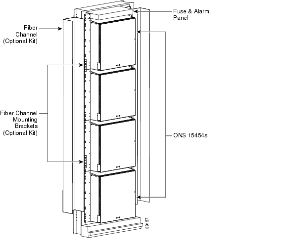
Figure 7-16 shows a typical bay arrangement using four 15454-SA-HD shelf assemblies. Note that most standard (Telcordia GR-63-CORE, 19-inch [482.6 mm] or 23-inch [584.2 mm]) seven-foot (2,133 mm) racks can hold four ONS 15454s and a fuse and alarm panel.
Figure 7-16 Typical 4-Shelf Equipment Rack Arrangement
Mounting a Single Shelf
Mounting the ONS 15454 in a rack requires a minimum of 18.5 inches (469.9 mm) of vertical rack space and one additional inch (25.4 mm) for air flow. To ensure that the mounting is secure, use two to four #12-24 mounting screws for each side of the shelf assembly. Figure 7-17 shows the rack mounting position for the ONS 15454.
Figure 7-17 Mounting an ONS 15454 in a Rack
Mounting Multiple Shelves
If incremental shelves are to be installed, Cisco recommends that they be installed from the bottom of the equipment rack to the top to simplify cabling. However, shelves may be added in any position so long as proper bay cabling is selected.
Incremental ONS 15454 shelves can be installed by local technicians. Most standard seven-foot racks can hold four ONS 15454 shelves and a fuse and alarm panel. However, unequal flange racks are limited to three ONS 15454 shelves and a fuse and alarm panel or four ONS 15454 shelves and a fuse and alarm panel from an adjacent rack.
If you plan to use the external (bottom) brackets to install the fan-tray air filter, you can install three shelf assemblies in a standard seven-foot rack. If you do not use the external (bottom) brackets, you can install four shelf assemblies in a rack. The advantage to using the bottom brackets is that you can replace the filter without removing the fan tray.
OSP Cabinet Installations
The ONS 15454 is industrial temperature rated and can be installed in outside plant (OSP) cabinets when configured with the following components:
•
•
•
•
•
•
•
•
•
•
•
•
•
•
•
•
•
•
•
•
•
•
•
•
•
Note
Power and Grounding
For proper operation, the ONS 15454 must be powered from a power source that can provide sufficient wattage at a specific voltage. These two factors, in addition to how they relate to amperage, must be taken into consideration when choosing a power source for the ONS 15454. Table 7-19 lists the power requirements for the ONS 15454.
Cisco recommends a 100-A fuse panel (30-A fuse per shelf minimum) if you install the 15454-SA-ANSI or 15454-SA-HD shelf. If you install the 15454-SA-NEBS3 shelf, Cisco recommends you use a standard 80-A fuse panel (20-A fuse per shelf minimum).
Power Supplies
The power supply required for proper operation of a Cisco ONS 15454 is dependent on your specific needs and ONS 15454 shelf configuration. To learn more about Cisco power supplies, see http://cisco.com/en/US/products/ps6063/index.html.
Cisco does not endorse any specific vendor and recommends considering solutions from as many vendors as appropriate. Vendors listed below are a sampling of companies providing power solutions suitable for the Cisco ONS 15454. Information regarding these vendor's products can be found on their respective Web sites.
•
•
•
•
Power Feeds
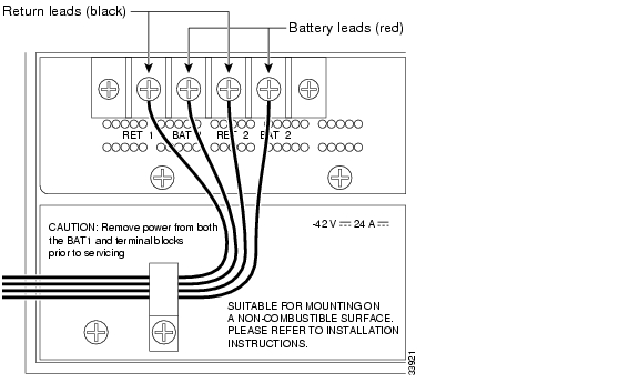
The ONS 15454 has redundant -48VDC power feeds on the shelf assembly backplane. Power terminals (shown in Figure 7-18) are #8-32 screws, labeled RET1, BAT1, RET2, and BAT2, and are located on the lower section of the assembly shelf backplane. The power terminals will accept a conductor lug with a width up to 0.378 inches.
Figure 7-18 Power Feed Connections
To install redundant power feeds, use four #10 AWG (copper conductor, 194ΑF [90ΑC]) power cables, one ground cable (#10 AWG, copper conductor, 194ΑF [90ΑC]) from the 15454 shelf to the equipment rack, and one ground cable (#6 AWG) from the equipment rack to central office. Use a conductor with low impedance to ensure circuit overcurrent protection. However, the conductor must have the capability to safely conduct any faulty current that might be imposed. Cisco recommends the following wiring conventions illustrated in Figure 7-18:
•
•
•
When terminating battery and battery return connections as shown in Figure 7-18, follow a torque specification of 10 in-lb.
Note
The black plastic dielectric dividers shown in Figure 7-19 isolate the A and B power feeds. This design better protects against voltage spikes and accidental shorting.
Figure 7-19 Dielectric Power Block
The redundant -48VDC is distributed through the backplane to each of the 17 card slots. Every ONS 15454 card contains ORing diodes to isolate the battery feeds, inrush-limiting and filtering circuitry, and local switching regulation. Wire-wrap pins on the backplane provide frame grounds to minimize any transient voltage or current disruptions to the system when a card is inserted in the shelf.
Power Monitoring
The Alarm Interface Controller-International (AIC-I) card provides a power monitoring circuit that monitors the supply voltage of -48 VDC for presence, under voltage, or over voltage.
The TCC2/TCC2P also monitors both A and B supply voltage inputs of the assembly shelf. It Overrides the AIC-I card and will force the AIC-I LEDs to match Power Monitor LEDs on the TCC2/TCC2P. The TCC2/TCC2P is capable of detecting a blown fuse based on shared knowledge between the active and standby TCC2/TCC2Ps. An alarm will be generated if one of the supply voltage inputs has a voltage out of the specified range of -40.5 to -57VDC.
Ground Connections
The frame ground posts are two #10-32 studs measuring 5/8 inch center-to-center to accommodate a dual-hole lug. The nuts provided for a field connection includes integral lock washers. The lug must be rated to accept the #10 AWG cable. Figure 7-20 shows the location of the ground posts.
Figure 7-20 Ground Posts on the ONS 15454 Backplane
Ground only one cable to ground the shelf assembly. Terminate the other end of the ground cable to ground according to local site practice. Connect a ground terminal for the frame ground (FGND) terminal according to local site practice.
Note
Figure 7-21 shows the typical power and grounding wiring for a four-shelf Central Office bay.
Figure 7-21 Typcial Central Office Bay Power and Grounding
Alarm and Control Connections
For environmental alarms and power monitoring, use the Alarm Interface Controller (AIC) card with ONS 15454 systems running software prior to R3.4, or use the Alarm Interface Controller-International (AIC-I) card for systems running Software Release 3.4 and higher. The ONS 15454 shelf assembly supports the termination of multiple environmental alarms. Table 7-20 details the alarm termination capacities of the AIC and AIC-I cards based upon the equipment configuration. LEDs on the front panel of the AIC and AIC-I cards indicate the status of the alarm lines, one LED representing all the inputs and one LED representing all the outputs. The physical connections are made using the backplane wire-wrap pins listed in the Alarm Pins section of this document.
External alarms (input contacts) are typically used for external sensors such as open doors, temperature sensors, flood sensors, and other environmental conditions. External controls (output contacts) are typically used to drive visual or audible devices such as bells and lights, but they can control other devices such as generators, heaters, and fans.
You can program each of the input alarm contacts separately. Choices include Alarm on Closure or Alarm on Open, an alarm severity of any level (Critical, Major, Minor, Not Alarmed, Not Reported), a Service Affecting or Non-Service Affecting alarm-service level, and a 63-character alarm description for CTC display in the alarm log. You cannot assign the fan-tray abbreviation for the alarm, because the abbreviation reflects the generic name of the input contacts. The alarm condition remains raised until the external input stops driving the contact or you provision the alarm input.
The output contacts can be provisioned to close on a trigger or to close manually. The trigger can be a local alarm severity threshold, a remote alarm severity, or a virtual wire as follows:
•
•
•
You can also program the output alarm contacts (external controls) separately. In addition to provisionable triggers, you can manually force each external output contact to open or close. Manual operation takes precedence over any provisioned triggers that might be present.
Alarm Pins
The alarm pin field supports up to 17 alarm contacts, including four audible alarms, four visual alarms, one alarm cutoff (ACO), and four user-definable alarm input and output contacts.
Audible alarm contacts are in the LOCAL ALARM AUD pin field and visual contacts are in the LOCAL ALARM VIS pin field. Both of these alarms are in the LOCAL ALARMS category. User-definable contacts are in the ENVIR ALARM IN (external alarm) and ENVIR ALARM OUT (external control) pin fields. These alarms are in the ENVIR ALARMS category and you must have the AIC or AIC-I card installed to use the ENVIR ALARMS. Alarm contacts are Normally Open (N/O), meaning that the system closes the alarm contacts when the corresponding alarm conditions are present. Each alarm contact consists of two wire-wrap pins on the shelf assembly backplane. Visual and audible alarm contacts are classified as critical, major, minor, and remote.
The 15454-AIC-I card requires an 15454-SA-ANSI or 15454-SA-HD shelf assembly running Software Release 3.4.0 or higher. The backplane of the 15454-SA-ANSI and 15454-SA-HD shelves contain a wire-wrap field with pin assignment according to the layout in Figure 7-22.
Figure 7-22 ONS 15454 Backplane Pinouts (System Release 3.4 and higher)
Figure 7-23 shows alarm pin assignments using the 15454-AIC in a 15454-SA-NEBS3E shelf for Release 3.3 and earlier.
Figure 7-23 ONS 15454 Backplane Pinouts (prior to System Release 3.4)
Visual and audible alarms are typically wired to trigger an alarm light or bell at a central alarm collection point when the corresponding contacts are closed. You can use the Alarm Cutoff pins to activate a remote ACO for audible alarms. You can also activate the ACO function by pressing the ACO button on the TCC+/TCC2/TCC2P card faceplate. The ACO function clears all audible alarm indications. After clearing the audible alarm indication, the alarm is still present and viewable in the Alarms tab in CTC.
Alarm Expansion Panel
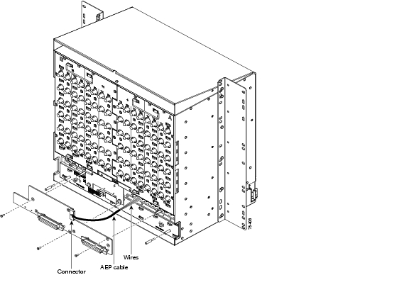
The optional ONS 15454 alarm expansion panel (AEP) can be used with the Alarm Interface Controller card (AIC-I) card to provide upto 48 dry alarm contacts for the ONS 15454, 32 of which are inputs and 16 are outputs. The AEP is a printed circuit board assembly that is installed on the backplane. Typically, the AEP is preinstalled when ordered with the ONS 15454; however, the AEP can be ordered separately. The AIC-I card must be installed before you can provision the alarm contacts enabled by the AEP. Figure 7-24 shows how an AEP is attached to the backplane of an assembly shelf.
Figure 7-24 Attaching an AEP to the Backplane
Note
Each AEP alarm input port has provisionable label and severity. The alarm inputs have optocoupler isolation. They have one common 32VDC output and a maximum of 2 mA per input. Each opto metal oxide semiconductor (MOS) alarm output can operate by definable alarm condition, a maximum open circuit voltage of 60 VDC, and a maximum current of 100 mA.
Figure 7-25 shows where the AEP cable wires connect to the wire-wrap pins on the backplane of the assembly shelf. Table 7-21 shows the wire-wrap pin assignments and corresponding signals on the AIC-I and AEP.
Figure 7-25 AEP Wire-Wrap Connections to Backplane Pins
Connecting to external alarm sources via the Amp Champ cable must be done according to Table 7-22.
Use the pin numbers in Table 7-23 to connect to the external elements being switched by external alarms.
Timing Connections
The ONS 15454 backplane supports two building integrated timing supply (BITS) clock pin fields. The first four BITS pins, rows 3 and 4, support output and input from the first external timing device. The last four BITS pins, rows 1 and 2, perform the identical functions for the second external timing device.
Cisco recommends using 100 ohm shielded BITS clock cable pair #22 or #24 AWG (0.51 mm≤ or 0.64 mm≤), twisted-pair T1-type when connecting an ONS 15454 to a BITS input cable. Wrap the clock wires on the appropriate wire-wrap pins according to local site practice. Ground the shield of the BITS input cable at the BITS end. For BITS output, wrap the ground shield of the BITS cable to the frame ground pin (FG1) located beneath the column of BITS Pins. Table 7-24 lists the pin assignments for the BITS timing pin fields.
Operations Systems (OSS) LAN Connections
Use the LAN pins on the ONS 15454 backplane to connect the ONS 15454 to an OSS LAN or to a LAN modem for remote access to the node. You can also use the TCP/IP Ethernet port on the TCC+, TCC2, or TCC2P faceplate to connect a PC to the network. Table 7-25 shows the LAN pin assignments.
Table 7-25 ONS 15454 LAN Pin Assignments
LAN 1
Connecting to data circuit-terminating equipment (DCE1 ) such as a hub or switch
B2
1
A2
2
B1
3
A1
6
LAN 1
Connecting to data terminal equipment (DTE) such as a PC, workstation or router
B1
1
A1
2
B2
3
A2
6
1 The Cisco ONS 15454 is a DCE.
An optional RJ45 jack-to-wire-wrap cable is also available that allows the backplane LAN pins to be terminated using an RJ-45 interface attached to the equipment rack (see Figure 7-26). The RJ45 jack-to-wire-wrap cable and bracket is part of the accessory kit, 53-2329-01, which ships with the following product IDs:
•
•
•
Figure 7-26 Optional RJ45 Jack-to-Wire-Wrap Cable and Connector Installation
Note
Note
For more information about IP address requirements, refer to Chapter 8 in this document.
TL1 Craft Interface
You can use the craft pins on the assembly shelf backplane or the EIA/TIA-232 port on the TCC2/TCC2P card faceplate to create a VT100 emulation window to serve as a TL1 craft interface to the ONS 15454. Use a straight-through cable to connect to the EIA/TIA-232 port. Table 7-26 shows the pin assignments for the CRAFT pin field.
Note
Table 7-26 TL1 Craft Interface Pin Assignments
Craft
A1
Receive
A2
Transmit
A3
Ground
A4
DTR
Cabling
Cables are not included with the ONS 15454 and must be ordered separately. Coaxial cables for the BNC EIAs, optical interface cables, and CAT-5 Ethernet cables that have been approved for use with the ONS 15454 can be ordered from the following third party vendors:
•
•
•
•
•
•
•
•
•
•
•
•
Cisco provides cable assemblies for the following EIAs:
•
•
•
•
Cable assemblies that can be ordered through Cisco are listed in Table 7-27, Table 7-28, and Table 7-29:
Table 7-27 Cisco ONS 15454 Low-Density Cable Assemblies
15454-EIA-BNC-*961
15454-CA-HDBNC-30
Mini BNC to standard BNC (unterminated), 75 Ohm.
30
15454-CA-HDBNC-75
75
15454-EIA-AMP-*84
15454-AMP-WW-30
AMP Champ unterminated wire-wrap cable
30
15454-AMP-WW-50
50
15454-AMP-WW-100
100
15454-AMP-WW-250
250
15454-EIA-SMB-*84
15454-SMB-BNC-10
SMB to BNC cable assembly
10
15454-SMB-BNC-30
30
15454-SMB-BNC-50
50
1 * denotes side of shelf (A or B)
Table 7-30 lists the maximum length of cable you can have between the EIA and patch panel or cross-connect frame.
When using the RG-179 coaxial cable on an EIA, the maximum distance available is less than the maximum distance available with standard RG-59 (734A) cable. The shorter maximum distance available with the RG179 is due to a higher attenuation rate for the thinner cable. The following attenuation rates are calculated using a DS-3 signal:
•
•
Cable Routing and Management Overview
The ONS 15454 cable routing and management facilities include the following:
•
•
•
•
•
•
•
•
•
•
Figure 7-27 Cable Management Tray and Fold Down Front Door
Managing Fiber Optic Cables
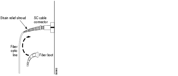
Fiber boots (15454-Fiber-Boot=) are included with ONS 15454 OC-N cards that do not have angled optical port to protect the fiber from excessive bending. The fiber boot is placed over the jumper's strain relief shroud connected to the SC connector as shown in Figure 7-28.
Figure 7-28 Fiber Boot Attachment
Note
If you are installing an OC3IR/STM1SH 1310-8 card, you must use a fiber clip instead of a fiber boot on the Port 8 Rx fiber connector.
Fiber clips are factory-attached to the faceplate of OC-N cards.
GBICs do not have fiber clips; therefore, if you are routing fiber from an E1000-2-G, E1000-2, G1000-2-G, G10002, or FC_MR-4 card, route the fiber cables into the cable-management tray.
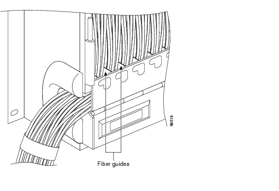
Route the fiber cables out either side of the cable-management tray through the cutouts on each side of the shelf assembly. The jumper routing fins and posts are designed to route fiber jumpers out of both sides of the shelf. Slots 1 to 6 exit to the left, and Slots 12 to 17 exit to the right. Figure 7-29 shows fibers routed from cards in the left slots, down through the fins, then exiting out the fiber channel to the left.
Figure 7-29 Fiber Optic Cable Guides
Figure 7-30 shows fiber jumpers routed out of both sides of the shelf from any card slot using the universal jumper routing posts.
Figure 7-30 Universal Jumper Routing with Posts
The maximum capacity of the fiber routing channel depends on the jacket diameter of the fiber jumpers. Table 7-31 gives the maximum capacity of the fiber channel for each side of the shelf, for the different fiber sizes.
Plan your fiber size according to the number of cards/ports installed in each side of the shelf. For example, if your port combination requires 36 fibers, 3 mm (0.11 inch) fiber is adequate. If your port combination requires 68 fibers, you must use 2 mm(0.7 inch) or smaller fibers.
Managing Ethernet Cables
The CE-100T-8, E100T-12, E100T-12G, and ML100-12 Ethernet cards have RJ-45 connectors on the faceplate for client interfaces and do not require an EIA. Use the universal jumper posts or remove the cable routing guides, if necessary, to create a larger opening for Cat 5 Ethernet cables.
Note
Note
Figure 7-31 Cat 5 Cable Management with Cable Routing Guides Removed
Figure 7-32 shows the door to the ONS 15454 closed after fully cabling all twelve RJ-45 ports on four 10/100 Ethernet cards.
Figure 7-32 Door Closed with Four 12-Port 10/100 Ethernet Cards Fully Cabled
Use an RJ-11 to RJ-45 console cable adapter, and a DB-9 adapter to connect a PC to the console port on ML100-12 and ML-1000-2 cards. Figure 7-33 shows an RJ-11 cable connected to the console port on the ML1000-2 faceplate via an RJ-11 to RJ-45 cable adapter. The console port on the ML100-12 is at the bottom of the card faceplate.
Figure 7-33 Connecting to the ML-Series Console Port
Managing Coaxial Cables
When using coaxial cables, the cables must terminate on an EIA installed on the shelf assembly backplane. All cables connected to ONS 15454 low-density (LD) DS3-12, DS3-12E, DS3XM-6, DS3XM-12, or EC1-12 cards and high-density (HD) DS3/EC1-48 cards must terminate with coaxial cables using the desired connector type to connect to the specified EIA.
The electromagnetic compatibility (EMC) performance of the node depends on good-quality coaxial cables, such as Shuner Type G 03233 D, or the equivalent.
The SMB EIA supports AMP 415484-1 75-ohm 4-leg connectors. Right-angle mating connectors for the connecting cable are AMP 415484-2 (75-ohm) connectors. Use RG-179/U cable to connect to the ONS 15454 EIA. Cisco recommends these cables for connection to a patch panel; they are not designed for long runs. Range does not affect loopback testing.
The BNC and High-Density BNC EIAs support BNC connectors. The MiniBNC EIA supports mini BNC connections.
The connector pairs on the BNC EIAs are marked "Tx" and "Rx" to indicate transmit and receive cables for each port. The MiniBNC EIA also supports the following J-Labeling that corresponds BNC connectors to the ports on low- and high-density electrical interface cards.
Table 7-32 and Table 7-33 show the J-labeling and corresponding card ports for a shelf assembly configured with low-density electrical cards.
Table 7-34 and Table 7-35 show the J-labeling and corresponding card ports for a shelf assembly configured with high-density 48-port DS-3/EC-1electrical cards.
Due to the large number of MiniBNC connectors on the MiniBNC EIA, you might require a special tool for inserting and removing MiniBNC EIAs ( Figure 7-34. This tool also helps with ONS 15454 patch panel connections.
Figure 7-34 MiniBNC Insertion and Removal Tool
This tool can be obtained with P/N 227-T1000 from:
Amphenol USA (www.amphenol.com)
One Kennedy Drive
Danbury, CT 06810
Phone: 203 743-9272 Fax: 203 796-2032This tool can be obtained with P/N RT-1L from:
Trompeter Electronics Inc. (www.trompeter.com)
31186 La Baya Drive
Westlake Village, CA 91362-4047
Phone: 800 982-2629 Fax: 818 706-1040Managing Twisted-Pair Cables
Twisted-pair wire-wrap cables require SMB EIAs and DS-1 electrical interface adapters (baluns). Connect twisted-pair cables to SMB EIAs on the shelf assembly backplane using cable connectors and DS-1 baluns. Installing twisted-pair, wire-wrap cables to terminate DS-1 signals requires separate pairs of grounded twisted-pair wires for receive (in) and transmit (out). Prepare four cables, two for receive and two for transmit, for each DS-1 facility to be installed.
Note
As shown in Figure 7-35, each DS-1 balun has a female SMB connector on one end and a pair of 0.045 inch (1.14 mm) square wire-wrap posts for tip and ring connections on the other end. The wire-wrap posts are 0.200 inches (5.08 mm) apart.
Figure 7-35 DS-1 Balun
Managing AMP Champ Cables
Amp Champ cables are used to terminate DS-1 signals on an ONS 15454. When using Amp Champ cables, you must equip the ONS 15454 with an AMP Champ EIA on each side of the shelf assembly backplane where DS-1 cables will terminate. Each AMP Champ connector on the EIA corresponds to a slot in the shelf assembly and is numbered accordingly. The AMP Champ connectors have screw-down tooling at each end of the connector.
Tie wrap or lace the AMP Champ cables according to local site practice and route the cables. If you configure the ONS 15454 for a 23-inch (584.2 mm) rack, two additional inches (50.8 mm) of cable management area is available on each side of the shelf assembly.
To install AMP Champ connector cables to terminate DS-1 signals, you must use 64-pin bundled cable connectors with a 64-pin male AMP Champ connector. You need an AMP Champ connector #552276-1 for the receptacle side and #1-552496-1 (for cable diameter .475in.-.540in.) or #2-552496-1 (for cable diameter .540in.-.605in.) for the right-angle shell housing (or their functional equivalent). The corresponding 64-pin female AMP Champ connector on the AMP Champ EIA supports one receive and one transmit for each DS-1 port for the corresponding card slot.
Because each DS1-14 card supports fourteen DS-1 ports, only 56 pins (28 pairs) of the 64-pin connector are used. Prepare one 56-wire cable for each working DS1-14 card installed.
Table 7-36 shows the pin assignments for the AMP Champ connectors on the ONS 15454.
Table 7-37 shows the pin assignments for the AMP Champ connectors on the ONS 15454 AMP Champ EIA for a shielded DS-1 cable.
Managing UBIC Cables
The UBIC-H and UBIC-V DS-1 and DS3/EC-1 cable assemblies are designed to support both low-density (LD) and high-density (HD) DS-1, DS-3, or EC-1 signals. One end of these cables is terminated with a 50-pin SCSI connector and the other end is unterminated. Each SCSI connector on the DS-1 cable assembly supports 14 separate Tx and Rx DS-1 twisted-pair, 24 AWG cables. Each SCSI connector on the DS-3/EC-1 cable assembly supports 12 separate Tx and Rx DS-3 RG734 to RG735A coaxial cables. If available, tie wrap or lace the cables to the optional ONS 15454 tie-down bar according to GR-1275-CORE or local site practice.
Note
Figure 7-36 shows the pin locations on the DS-1 and DS-3/EC-1 SCSI connectors.
Figure 7-36 SCSI Cable Connector Pins
Table 7-38 shows the SCSI connector pin assignments for the DS-1 and DS-3/EC-1 cables.
Table 7-39 shows the UBIC-H and UBIC-V EIA DS-1 cable wiring.
DS-1 Cables
The DS-1 cables are connectorized at the ONS 15454 shelf end and must be wire-wrapped at the DSX end. Each Tx/Rx pair of SCSI connectors will support 140 DS-1s. A total of ten low-density (LD) DS-1 cards in slots 1, 2, 4, 5, 6, 12, 13, 14, 16, and 17 fully cabled can support 140 DS-1 drops. Four high-density (HD) cards in slots 1, 2, 16, and 17 fully cabled will have 224 DS-1 drop capacity when the HD DS-1 card becomes available.
Note
DS-3/EC-1 Cables
The DS-3/EC-1 cable assemblies are used for the DS3-12, DS3-12E, DS3/EC1-48, DS3XM-6, DS3XM-12, and EC1-12 cards. The DS-3/EC-1 cables are connectorized at the UBIC Vend and unterminated at the far end. Twelve individual BNC connectors are supplied with each cable assembly in a separate package.
Each Tx/Rx pair of SCSI connectors will support 12 DS-3s or EC-1s. A total of ten LD DS-3 or EC-1 cards in slots 1, 2, 4, 5, 6, 12, 13, 14, 16, and 17 fully cabled can support 120 DS-3 or EC-1 drops. Four HD DS-3/EC-1 cards in slots 1, 2, 16, and 17 fully cabled will have 192 DS-3/EC-1 drop capacity.
Each Tx/Rx pair of SCSI connectors will also support 6 channelized DS-3s drops for the DSXM-6 and 12 channelized drops for the DS3XM-12 cards. Fully cabled the UBIC-H and UBIC-V can support 36 DS3XM-6 drops or 72 DS3XM-12 drops.
The UBIC-H and UBIC-V EIAs support the following J-Labeling that corresponds SCSI connectors to the ports on low- and high-density electrical interface cards.
Table 7-40 and Table 7-41 show the J-labeling and corresponding card ports for a shelf assembly configured for low-density electrical cards.
Table 7-42 and Table 7-43 show the J-labeling and corresponding card ports for a shelf assembly configured with high-density 48-port DS-3/EC-1 or 56-port DS-1 electrical cards.
DSX Wiring Verification Kits
The ONS 15454 DSX Wiring Verification Kit consists of an In-service test card (IS-DSX), hand-held control unit (TU-DSX-RR), a circuit card that plugs into the ONS 15454 shelf assembly (TU-DSX TEST UNIT), plus several patch cords and an AC/DC adaptor. The TU-DSX TEST UNIT works in Slots 3 and 15 of the Shelf assembly and gets power from either the shelf's office battery or from an optional low power AC/DC adaptor. The kit verifies installed cabling between the cross-connect DS-1 or DS-3 patch panel and a newly installed ONS 15454 shelf (see Figure 7-39). Tested conditions are for shorts, opens, wrong connections, and tip/ring reversals. Once testing is started, the DSX wiring can be verified at the DSX. There is no need for coordinated operations at both the DSX and the ONS 15454 shelf. For more information about the DSX wiring verification kit, refer to the Cisco Testing DSX Wiring with the Cisco ONS 15454 DSX Wiring Verification Kit document (74-3494-01-A0 Issue 3).
Figure 7-37 ONS 15454 DSX Wiring Verification Kit Block Diagram
Electrical Cable Management Using the Optional Tie-Down Bar
Optional ONS 15454 tie-down bars, 19 inches and 23 inches, can be used to provide a diverse path for redundant power feeds and EIA cables. You can install a 5-inch (127 mm) tie-down bar on the equipment rack at the rear of the assembly shelf. You can use tie-wraps or other site-specific material to bundle the cabling and attach it to the bar so that you can more easily route the cable away from the rack. Figure 7-38 shows the tie-down bar, the ONS 15454 shelf assembly, and the equipment rack.
Figure 7-38 EIA Cable Management Using the Optional Tie-Down Bar
Standoffs and Rear Plastic Cover
The ONS 15454 has an optional clear plastic rear cover that provides additional protection for the cables and connectors on the EIAs.
Optional spacers are included in the rear cover ship kit to provide the necessary space between the cables and rear covers for the UBIC-H and UBIC-V. You will need the following equipment to install the standoffs (necessary for installing the rear cover with over UBIC-V EIA cables) and the rear cover:
•
•
•
•
•
•
•
You attach the rear cover by hanging it from the mounting screws on the back of the mounting brackets and pulling it down until it fits firmly into place (see Figure 7-39).
Figure 7-39 Installing the Rear Cover with Standoffs
Synchronization
The Cisco ONS 15454 is designed to operate in a network that complies with synchronization and timing recommendations stated in GR-253-CORE, GR-436-CORE, and GR-1244-CORE.
SONET timing parameters must be set for each ONS 15454. Each ONS 15454 independently accepts its timing reference from one of three sources:
1.
2.
3.
You can set ONS 15454 timing to one of three modes: external, line, or mixed. If timing is coming from the BITS pins, set the ONS 15454 timing to external. If the timing comes from an OC-N card, set the timing to line. Node timing for a typical ONS 15454 network would be as follows:
•
•
You can set three timing references for each ONS 15454. The first two references are typically two BITS-level sources, or two line-level sources optically connected to a node with a BITS source. The third reference is the internal clock provided on every ONS 15454 TCC2/TCC2P card. This clock is a Stratum 3 (ST3). If an ONS 15454 becomes isolated, timing will be maintained at the ST3 level.
Release 5.0 supports a new 64KHz+8KHz composite clock reference, per ITU-T G.703 Table II.1. The 64KHz+8KHz clock features AMI with 8 KHz bipolar violation, and only works with dual TCC2P cards running software Release 5.0 and higher.
You can select the 64KHz+8KHz clock from the Facility Type selection box in the BITS Facilities subtab of the node view, Provisioning > Timing tabs. When using the 64KHz+8KHz clock as a source, only DS1 and 6MHz framing are allowed for BITS out, and the user selected Admin SMM message type is enforced, with the Sync Messaging check box disabled and grayed out. With the 64KHz+8KHz clock selected as the source, the user selectable Admin SSM defaults to STU. The following configurations are supported for the 64+8kHz clock:
•
•
•
•
•
•
•
Caution
Timing Guidelines
Timing guidelines for the ONS 15454 evolve around the following conditions:
•
•
•
Timing and Synchronization Features
Timing and synchronization in the ONS 15454 is controlled by the TCC2/TCC2P card which is stratum 3 compliant. A redundant architecture protects against failure or removal of one TCC2/TCC2P card. For timing reliability, the TCC2/TCC2P card selects either a recovered clock, a BITS clock, or an internal stratum as the system timing reference. You can provision any of the clock inputs as primary or secondary timing sources. If you provision two timing references, the secondary reference provides protection. A slow-reference tracking loop allows the TCC2/TCC2P to track the selected timing reference and synchronize to the recovered clock and provide holdover in the event the reference is lost. In a fail-over scenario, selection of the next timing reference is governed by the availability of the next best (clock quality) timing reference as defined by the Stratum hierarchy (discussed in the next section). The timing modes available on the ONS 15454 include the following:
•
•
•
•
•
Warning
Through-timing and per-port loop timing are additional timing modes available, but are not supported for the optical synchronous interfaces. DS1 and DS3 asynchronous interfaces are through-timed and do not reference the system timing. For these asynchronous ports, transmit timing is derived from the received timing for that asynchronous signal.
The transmit timing on all optical synchronous interfaces is derived from the system timing reference provided by the TCC2/TCC2P cards. Figure 7-40 illustrates how timing signals flow through the ONS 15454. The TCC2/TCC2P card selects a timing reference from one of several sources as discussed above and distributes this reference to the synchronous interface cards.
Figure 7-40 ONS 15454 Timing Flow
The TCC2/TCC2P synchronization functions include:
•
•
•
•
•
•
External BITS Timing
The external timing input signal on the Cisco ONS 15454 must come from a synchronization source whose timing characteristics are better than the stratum 3 internal clock. The TCC2/TCC2P will track the external reference with the internal clock.
The BITS signal is a DS-1 level, 1.544 MHz signal, formatted either as D4 Superframe (SF, 12 frames per superframe) or the Extended Superframe (ESF, 24 frames per superframe) ESF. For the ONS 15454, the default setting for the BITS framing reference is ESF, but you may change this to SF (D4) if necessary. The default setting for BITS line coding reference is B8ZS, however this can be changed to AMI if required. The default setting for BITS State is OOS (out of service). For nodes using external timing or the external BITS Out, you must change this setting to IS (in-service). The redundant architecture of the ONS 15454 provides two inputs for connection to external BITS clocks: BITS1 and BITS2. If these inputs have been selected as the primary and secondary synchronization sources, the active and standby TCC2/TCC2P cards will monitor both inputs. If the primary input fails, the secondary input will be selected. Failure switching is discussed in more detail later. It is recommended, but not necessary, to have redundant BITS inputs. However, if only a single BITS source is available, the secondary source can be set to Internal or Line synchronization.
Note
Table 7-44 provides a summary of the BITS input physical connections and signal formats for the ONS 15454.
Line Timing
The ONS 15454 can accept reference timing from any optical port. For increased reliability, optical cards with multiple ports (e.g. 4-port OC-3) can only have one of its ports provisioned as a timing reference. The optical cards divide down the recovered clock to 19.44 MHz and transmit it to the working and protect TCC2/TCC2P cards, where it is qualified for use as a timing reference.
Synchronization Status Messaging (SSM) can be optionally enabled or disabled on an optical port. A controller on the optical card monitors the received SSM and reports any changes to the TCC2/TCC2P synchronization process. If an optical port (receiver) is selected as the active timing reference, the SSM value DUS (Don't Use for Synchronization) is transmitted (on the transmit port) to help prevent timing loops. If SSM is disabled, the controller does not monitor the received SSM value and transmits the SSM value STU (Synchronized, Traceability Unknown). More information on SSM is available later in this chapter.
Mixed Mode Timing
Caution
The Mixed Mode Timing feature enhances the provisioning options for the NE Reference only. The rules associated with the BITS Out timing source have not changed. To review these rules, Figure 7-41 has been provided to show the ONS 15454 timing circuit.
Figure 7-41 ONS 15454 Timing Circuit
The operation of the timing circuit shown above is as follows:
•
•
•
•
Note
Free-running Mode
The ONS 15454 is considered to be in Free-run state when it is operating on its own internal clock. The ONS 15454 has an internal clock in the TCC2/TCC2P that is used to track a higher quality reference, or in the event of node isolation, provide holdover timing or a free-running clock source. The internal clock is a certified stratum 3 clock with enhanced capabilities that match the stratum 3E specifications for:
•
•
•
•
•
•
•
Table 7-45 provides the timing characteristics of stratum 3 and stratum 3E clocks, and compliance details for the ONS 15454.
Table 7-45 Stratum 3 and 3E Compliance
Free Run Accuracy
4.6 ppm
4.6 ppm
Comply with stratum 3E
Holdover Stability
Holdover - Initial Offset
50 ppb
1ppb
5 ppb
Holdover - Frequency Drift
4.63 x 10⁻⁷
1.16 x 10⁻⁸
Comply with stratum 3E
Holdover - Temperature Stability
280 ppb
10 ppb
Comply with stratum 3
Wander Tolerance
per GR-253
per GR-253
Comply with stratum 3E
Wander Transfer
0.1Hz
0.01Hz
Comply with stratum 3
Wander Generation
per GR-253
per GR-253
Comply with stratum 3E
Pull-In and Hold-In Reference
4.6 x 10⁻⁶
4.6 x 10⁻⁶
Comply with stratum 3E
Locking/Settling Time
700 ms
100 ms
Comply with stratum 3E
Phase Transients
Tolerance
1us
1us
Comply with stratum 3E
Generation
per GR-253
per GR-253
Comply with stratum 3E
Build-Out
None
>3.5us
Comply with stratum 3E1
1 Line Build Out (LBO) is not supported in system releases prior to Release 3.3.
Holdover Mode
Holdover is the operating condition of a clock that has lost its external references, but continues to use reference information that was acquired during normal operation. Holdover is a failover state after a system clock has been continuously "locked & synchronized" to a more accurate reference for more than 140 seconds. It "holds" the original operating parameters for a defined period. The holdover frequency will start to drift over time, particularly when the "holdover period" has expired. Holdover conditions can be caused by:
•
•
Holdover frequency is a measure of a clock's performance while in holdover mode. The holdover frequency offset for stratum 3 is 50 x 10-9 initially (the first minute), and an additional 40 x 10-9 for the next 24 hours. The ONS 15454 goes into Holdover when the last available reference is lost and the node was synchronized to that reference for more than 140 seconds. During this period, the internal clock is held at the last known value of the Phase Lock Loop (PLL) parameters when the node was still synchronized to the reference clock. If the holdover frequency value is corrupted, the ONS 15454 will switch to Free-run mode.
BITS Out
BITS Out provides a clock source for other network elements that do not have a BITS or Line clock source. In the ONS 15454, the BITS Out clock is extracted from an optical Line source, regardless of the selected timing mode (External, Line, or Mixed). If a BITS clock is available at the facility, the other network elements should be timed directly from the BITS source. In Line timed mode, in addition to the optical Line sources, the BITS Out Reference list includes 'NE Reference'. 'NE Reference' enables the node's active Line reference to be automatically selected as the BITS Out signal. This option is not available in External or Mixed timing modes.
Table 7-46 provides a summary of the physical connections and signal formats for BITS Out.
BITS Out framing of ESF or SF (D4) and coding of AMI or B8ZS formats are configured in the BITS Facilities section in the Cisco Transport Controller (CTC). The configured framing and coding formats apply to both, the BITS Out and BITS input signals.
For both ESF and SF (D4), BITS Out is a framed, "all ones" signal (not to be confused with AIS, which is an unframed "all ones" signal). SSM is available only with ESF framing. The SSM value of the selected optical reference for BITS Out is passed through to the BITS Out signal.
SSM is not available with SF (D4) formatted DS-1. However, to insure reliability, when the BITS Out signal is used with equipment in SF (D4) mode or with no SSM capability, an AIS Threshold Settings can be provisioned in CTC. In this configuration, AIS will be sent as the BITS Out signal when the quality level of all selected optical references fall below the set threshold. The connected equipment can then switch to an alternate timing reference. Figure 7-42 provides a list of conditions under which AIS will be sent on the BITS Out facility.
Figure 7-42 BITS Out AIS Conditions
Synchronization Status Messaging
The ONS 15454 node supports two sets of SSMs: Generation 1 and Generation 2. Generation 1 is the most widely used SSM message set. Generation 2 is a newer version that defines additional quality levels. Table 7-47 describes the Generation 1 message set and Table 7-48 describes the Generation 2 message set.
Caution
Caution
With Release 5.0 you can configure an SSM value for a timing source (either BITS-IN or Optical Line) by selecting from the "ADMIN. SSM" selection box in the BITS Facilities subtab of the node view, Provisioning > Timing tabs. This feature is useful when the selected external timing source has no SSM information. When you select the Admin SSM value, all switching decisions are subsequently made based on your selection. The same SSM value is transmitted out of the interface configured for BITS Out, and in transmit Optical S1. The DS1 BITS type with framing type SF(D4) only supports Admin SSM. The 64KHz+8KHz clock also only supports Admin SSM. ESF Framing must have Sync Messaging turned off (uncheck the check box) in order to enable Admin SSM selection. SONET nodes use the SSM Generation II message set, as defined in Table 4 of ANSI T1.101-1999.
Setting Quality of RES
RES is a user-defined SSM value that enables the quality level of a clock source to be set between any of the defined standard levels. For example, if there are two Stratum 1 sources in the network, with one being of slightly lower quality than the other (GPS source versus a Cesium source), its SSM value can be set to RES, instead of PRS. The Cesium source will be PRS. In every node in the network, Quality of RES can be set to "STU<RES<PRS". This setting defines PRS as the highest quality clock and RES as the next highest quality clock (RES is greater than STU, but less than PRS). The CTC screen in Figure 7-43 shows the available settings for RES. If the RES SSM is used in an ONS 15454 network, its assigned quality level must be provisioned in every node in the network. The default setting is RES=DUS.
Figure 7-43 Quality of RES Settings
Using the ONS 15454 Without SSM
Older BITS clock sources may not provide SSM to the ONS 15454 BITS input signals. In this case, Sync Messaging must be disabled in CTC for the BITS 1 and BITS 2 inputs. The SSM value of STU (Synchronized, Traceability Unknown) will be assigned to the BITS inputs and used in the S1 byte on the optical ports. Note that a different SSM value (such as PRS) cannot be provisioned for the S1 byte to manually define the quality of the node's clock. A BITS input is considered to be failed when AIS is present at the input.
Network Synchronization Design
In most ONS 15454 networks, at least one or more nodes must be set to External timing. All other nodes can be set to Line timing. The timing architecture should insure that timing loops do not occur when there is a network failure. Externally timed nodes receive timing from a BITS source wired to the BITS backplane pins. The BITS source, in turn, gets its timing from a PRS, such as a stratum 1 clock or GPS signal. In networks with multiple BITS sources, the "STU<RES<PRS" SSM value can be used as described earlier. The Line timed nodes receive timing from optical pots.
Caution
Number of Line Timed Spans (Daisy-chained)
Currently, test results validate that 13 line-timed nodes can be daisy-chained without any effect on timing wander and jitter. The timing architecture can be arranged such that a single Externally timed source can provide Line timing for 13 nodes in the east direction and 13 nodes in the west direction for a total of 26 nodes.
2R and 3R DWDM Spans
In spans with 2R (Re-shape and Re-amplify, but not Re-time) DWDM systems the synchronization characteristics are simply passed-through (i.e., jitter is passed through) and there is no effect on network synchronization. However, with 3R (Re-shape and Re-amplify, Re-time) DWDM systems, the re-timing must be done from a stratum 1 source.
Network Timing Example
Figure 7-44 shows a typical ONS 15454 network timing setup example. Node 1 is set to external timing. Two timing references are set to BITS. These are Stratum 1 timing sources wired to the BITS input pins on the backplane of Node 1. The third reference is set to internal clock. The BITS output pins on the backplane of Node 3 are used to provide timing to outside equipment, such as a Digital Access Line Access Multiplexer.
In the example, Slots 5 and 6 contain the OC-N trunk cards in each node. Timing at Nodes 2, 3, and 4 is set to line, and the timing references are set to the port of the trunk OC-N cards based on distance from the BITS source. NE Reference 1 is set to the port of the OC-N trunk card closest to the BITS source. At Node 2, the NE Reference 1 is the port of the OC-N card in Slot 5, because it is connected to Node 1. At Node 4, the NE Reference 1 is set to the port of the OC-N card in Slot 6, because it is connected to Node 1. At Node 3, the NE Reference 1 could be the port of either OC-N trunk card because they are equal distance from Node 1.
Figure 7-44 ONS 15454 Network Timing Example
Synchronization Failure Switching
Depending on the network condition, the ONS 15454 will operate in one of the following synchronization modes.
•
•
•
•
A timing reference is considered failed if its SSM message is traceable to a source that is worse than the quality of the ONS 15454 internal clock. For example, a node with an internal Stratum 3 clock would consider a reference to be failed if it has a SSM message traceable to SMC or ST4 clock. Also, the node will not select a reference for timing if it has the DUS (Don't Use for Synchronization) SSM message.
Synchronization Switching Example
The Cisco ONS 15454 generates the synchronization message in the outgoing SONET signals. The synchronization messaging allows the ONS 15454 nodes in a ring to maintain their correct configuration. In Figure 7-45, the BITS clock is connected to Node A and timing is maintained around the ring from Node A to Node E. The SSM is a Stratum 1 traceable signal that passes from Node A, (external timed) to all the other nodes (line timed).
Figure 7-45 Normal Operation
Fiber is cut between Node B and Node C, causing a failure. A ring failure in a system without SSM that uses simple reference switching results in a timing loop shown in Figure 7-46.
Figure 7-46 Ring Failure and Timing Loop
In a system using SSM, the fiber cut in Figure 7-47 interrupts the timing signal around the ring. Since Node C was the receiving clock from Node B (line timed), and has lost signal, Node C goes into short-term holdover and uses its internal clock.
Figure 7-47 Ring Failure with SSM
In Figure 7-48, synchronization message 1 is now being sent to Node E directly from Node A (counterclockwise) instead of clockwise around the ring. At this point, Node E switches to lime timing from Node A.
Figure 7-48 Synchronization Switch
Synchronization message S1 continues to Nodes E, D, and C in the counterclockwise direction as shown in Figure 7-49. All nodes switch their line timing to the line receiving S1, which allows Node C to exit holdover. At this point, the ring is reconfigured and all nodes are again synchronized to BITS.
Figure 7-49 Synchronization Reconfigures Around the Ring
Synchronization Switching Time
On a failure or when the SSM value indicates that a higher quality reference is available, switching is instantaneous. The Wait To Restore period is ignored if reversion to the higher priority reference is active. However, if two references have the same SSM value, the Wait To Restore period must elapse before the ONS 15454 will revert back to the higher priority reference.
Card Protection Configurations
The ONS 15454 provides 1+1 protection for OC-N cards and a variety of electrical card protection methods. This section describes the card protection configurations supported by the ONS 15454.
OC-N Card Protection
The ONS 15454 provides two optical card protection methods, 1+1 protection and optimized 1+1 protection. Specific optical card protection schemes depend on the optical cards in use.
OC-N protection switching occurs automatically in response to detected faults, as well as manual requests initiated by local or remote users. The Cisco ONS 15454 supports 50 milliseconds (ms) 1+1 unidirectional or bidirectional protection switching upon detecting a signal failure or condition such as LOS, LOF, AIS-L or high BER on one or more of the optical card's ports. Revertive and nonrevertive switching options are available down to the circuit level.
1+1 Protection
Any OC-N card can use 1+1 protection. With 1+1 port-to-port protection, ports on the protect card can be assigned to protect the corresponding ports on the working card. The working and protect cards do not have to be placed side by side in the node. A working card must be paired with a protect card of the same type and number of ports. For example, a single-port OC-12 must be paired with another single-port OC-12, and a four-port OC-12 must be paired with another four-port OC-12. You cannot create a 1+1 protection group if one card is single-port and the other is multiport, even if the OC-N rates are the same. The protection takes place on the port level, and any number of ports on the protect card can be assigned to protect the corresponding ports on the working card.
For example, on a four-port card, you can assign one port as a protection port on the protect card (protecting the corresponding port on the working card) and leave three ports unprotected. Conversely, you can assign three ports as protection ports and leave one port unprotected. In other words, all the ports on the protect card are used in the protection scheme.
1+1 span protection can be either revertive or nonrevertive. With nonrevertive 1+1 protection, when a failure occurs and the signal switches from the working card to the protect card, the signal stays switched to the protect card until it is manually switched back. Revertive 1+1 protection automatically switches the signal back to the working card when the working card comes back online. 1+1 protection is unidirectional and nonrevertive by default; revertive switching is easily provisioned using CTC.
Optimized 1+1 Protection
Optimized 1+1 protection is used in networks that mainly use the linear 1+1 bidirectional protection scheme. Optimized 1+1 is a line-level protection scheme using two lines, working and protect. One of the two lines assumes the role of the primary channel, where traffic is selected, and the other line assumes the role of secondary channel, which protects the primary channel. Traffic switches from the primary channel to the secondary channel based on either line conditions or an external switching command performed by the user. After the line condition clears, the traffic remains on the secondary channel. The secondary channel is automatically renamed as the primary channel and the former primary channel is automatically renamed as the secondary channel.
Unlike 1+1 span protection, 1+1 optimized span protection does not use the revertive or nonrevertive feature. Also, 1+1 optimized span protection does not use the Manual switch command. The 1+1 optimized span protection scheme is supported only on the Cisco ONS 15454 SONET using either OC3-4 cards or OC3-8 cards with ports that are provisioned for SDH payloads.
Optimized 1+1 is fully compliant with Nippon Telegraph and Telephone Corporation (NTT) specifications. With optimized 1+1 port-to-port protection, ports on the protect card can be assigned to protect the corresponding ports on the working card. The working and protect cards do not have to be installed side by side in the node. A working card must be paired with a protect card of the same type and number of ports. For example, a four-port OC-3 must be paired with another four-port OC-3, and an eight-port OC-3 must be paired with another eight-port OC-3. You cannot create an optimized 1+1 protection group if the number of ports do not match, even if the OC-N rates are the same.
The protection takes place on the port level, and any number of ports on the protect card can be assigned to protect the corresponding ports on the working card. For example, on a four-port card, you can assign one port as a protection port on the protect card (protecting the corresponding port on the working card) and leave three ports unprotected. Conversely, you can assign three ports as protection ports and leave one port unprotected.
Electrical Card Protection
This section covers the general concept of electrical card protection. Specific electrical card protection schemes depend on the type of electrical card as well as the electrical interface assembly (EIA) type used on the ONS 15454 backplane. Table 7-49 details the specific electrical card protection schemes.
In the table, high-density (HD) card type include the DS3/EC1-48 card. Low-density (LD) card types include the following:
•
•
•
•
•
•
Caution
1:1 Protection
In 1:1 protection, a working card in an even-numbered slot is paired with a protect card in an odd-numbered slot of the same type. If the working card fails, the traffic from the working card switches to the protect card. You can provision 1:1 to be revertive or nonrevertive. If revertive, traffic automatically reverts to the working card after the failure on the working card is resolved.
Table 7-50 provides supported 1:1 protection configurations by electrical card type.
Figure 7-50 shows 1:1 low-density card protection configurations support by type of EIA.
Figure 7-50 1:1 Protection Configurations for Low-Density Electrical Cards Supported by EIA Types
1:N Protection
1:N protection allows a single card to protect up to five working cards of the same DS-N level. 1:N cards have added circuitry to act as the protect card in a 1:N protection group. Otherwise, the card is identical to the standard card and can serve as a normal working card.
The physical DS-1 or DS-3 interfaces on the ONS 15454 backplane use the working card until the working card fails. When the node detects this failure, the protection card takes over the physical DS-1 or DS-3 electrical interfaces through the relays and signal bridging on the backplane.
Table 7-51 provides the supported 1:N configurations by electrical card, as well as the card types that can be used for working and protection cards.
Table 7-51 1:N Protection Configurations Supported by Electrical Card
DS1-14
DS1N-14
< 5
1, 2, 4, 5, 6
3
12, 13, 14, 16, 17
15
DS3-12
DS3N-12
< 5
1, 2, 4, 5, 6
3
12, 13, 14, 16, 17
15
DS3-12E
DS3N-12E
< 5
1, 2, 4, 5, 6
3
12, 13, 14, 16, 17
15
DS3/EC1-48
DS3/EC1-48
< 2
3
15
DS3XM-12
DS3XM-12
< 5 (Ported Mode)
1, 2, 4, 5, 6
3
12, 13, 14, 16, 17
15
< 7 (Portless Mode5 )
1, 2, 4, 14, 15 16, 17
3
1, 2, 3, 4, 14, 16, 17
15
1 A high-density electrical card inserted in Slot 1 restricts the use of Slots 5 and 6 to only optical, data, or storage cards.
2 A high-density electrical card inserted in Slot 2 restricts the use of Slots 4 and 6 to only optical, data, or storage cards.
3 A high-density electrical card inserted in Slot 16 restricts the use of Slot 14 to only optical, data, or storage cards.
4 A high-density electrical card inserted in Slot 17 restricts the use of Slots 12 and 13 to only optical, data, or storage cards.
5 Portless DS-3 Transmux operation does not terminate the DS-3 signal on the EIA panel.
1:N Protection Guidelines
The following rules apply to 1:N protection groups in the ONS 15454:
•
•
•
•
The ONS 15454 automatically detects and identifies a 1:N protection card when the card is installed in Slot 3 or Slot 15. However, the slot containing the 1:N card in a protection group must be manually provisioned as a protect slot because by default all cards are working cards.
For detailed procedures on setting up DS-1 and DS-3 protection groups, refer to the Cisco ONS 15454 Procedure Guide.
Figure 7-51 shows 1:N protection configurations supported for low-density electrical cards by type of EIA.
Figure 7-51 1:N Protection Configuration Supporteds for Low-Density Electrical Cards by EIA Types
Note
Figure 7-52 shows 1:N high-density card protection configurations support by type of EIA.
Figure 7-52 1:N Protection Configurations for High-Density Electrical Cards Supported by EIA Types
Revertive Switching
1:N protection supports revertive switching. Revertive switching sends the electrical interfaces (traffic) back to the original working card after the card comes back online. Detecting an active working card triggers the reversion process. There is a variable time period for the lag between detection and reversion, called the revertive delay, which you can set using the ONS 15454 software, CTC. To set the revertive delay, refer to the Cisco ONS 15454 Procedure Guide. All cards in a protection group share the same reversion settings. 1:N protection groups default to automatic reversion.
Unprotected Cards
Unprotected cards are not included in a protection scheme; therefore, a card failure or a signal error results in lost data. Because no bandwidth lies in reserve for protection, unprotected schemes maximize the available ONS 15454 bandwidth.
Figure 7-53 shows unprotected low-density electrical card configurations supported by type of EIA.
Figure 7-53 Unprotected Low-Density Electrical Card Configurations Supported by EIA Types
Figure 7-54 shows unprotected high-density electrical card configurations supported by type of EIA.
Figure 7-54 Unprotected High-Density Electrical Card Configurations Supported by EIA Types
External Switching Commands
The external switching commands on the ONS 15454 are Manual, Force, and Lockout. If you choose a Manual switch, the command will switch traffic only if the path has an error rate less than the signal degrade (SD) bit error rate threshold. A Force switch will switch traffic even if the path has SD or signal fail (SF) conditions; however, a Force switch will not override an SF on a 1+1 protection channel.
Transponder and Muxponder Card Protection
Two types of protection options are available for the ONS 15454 transponder and muxponder cards:
•
•
Y-Cable Protection
Y-cable protection is available for the ONS 15454 transponder and muxponder cards (TXP_MR_10G, TXP_MR_2.5G, MXP_MR_2.5G, and MXP_2.5G_10G). To create Y-cable protection, you create a Y-cable protection group for two TXP or MXP cards in CTC, then connect the client ports of the two cards physically with a Y-cable. The single client signal is sent into the receive (Rx) Y-cable and is split between the two TXP or MXP cards. The two transmit (Tx) signals from the client side of the TXP or MXP cards are combined in the TX Y-cable into a single client signal. Only the active card signal passes through as the single TX client signal. The other card must have its laser turned off to avoid signal degradation where the Y-cable joins. Figure 7-55 shows the Y-cable signal flow.
Note
Figure 7-55 Y-Cable Protection
Splitter Protection
Splitter protection, shown in Figure 7-56, is provided with the TXPP_MR_2.5G and MXPP_MR_2.5G cards. To implement splitter protection, a client injects a single signal into the client Rx port. An optical splitter internal to the card then splits the signal into two separate signals and routes them to the two trunk Tx ports. The two signals are transmitted over diverse optical paths. The far-end MXPP or TXPP card uses an optical switch to choose one of the two trunk Rx port signals and injects it into the Tx client port. When using splitter protection with two MXPP or TXPP cards, there are two different optical signals that flow over diverse paths in each direction. In case of failure, the far-end switch must choose the appropriate signal using its built-in optical switch. The triggers for a protection switch are LOS, LOF, SF, or SD.
Figure 7-56 Splitter Protection
Ethernet Protection
Cisco ONS 15454 Ethernet cards use the IEEE 802.1D Spanning Tree Protocol (STP) and IEEE 802.1W Rapid Spanning Tree Protocol (RSTP) for Layer 2 protection, and uses SONET for Layer 1 protection.
Spanning Tree
STP is a Layer 2 link management protocol that provides path redundancy while preventing loops in the network. For a Layer 2 Ethernet network to function properly, only one active path can exist between any two stations. Spanning-tree operation is transparent to end stations, which cannot detect whether they are connected to a single LAN segment or a switched LAN of multiple segments.
When you create fault-tolerant internetworks, you must have a loop-free path between all nodes in a network. The spanning-tree algorithm calculates the best loop-free path throughout a switched Layer 2 network. Switches send and receive spanning-tree frames, called bridge protocol data units (BPDUs), at regular intervals. The switches do not forward these frames, but use the frames to construct a loop-free path.
Multiple active paths among end stations cause loops in the network. If a loop exists in the network, end stations might receive duplicate messages. Switches might also learn end-station MAC addresses on multiple Layer 2 interfaces. These conditions result in an unstable network.
Spanning tree defines a tree with a root switch and a loop-free path from the root to all switches in the Layer 2 network. Spanning tree forces redundant data paths into a standby (blocked) state. If a network segment in the spanning tree fails and a redundant path exists, the spanning-tree algorithm recalculates the spanning-tree topology and activates the standby path.
When two interfaces on a switch are part of a loop, the spanning-tree port priority and path cost settings determine which interface is put in the forwarding state and which is put in the blocking state. The port priority value represents the location of an interface in the network topology and how well it is located to pass traffic. The path cost value represents media speed.
The ONS 15454 can operate multiple instances of STP to support VLANs in a looped topology. You can dedicate separate circuits across the SONET ring for different VLAN groups. Each circuit runs its own STP to maintain VLAN connectivity in a multi-ring environment.
You can also disable or enable STP on a circuit-by-circuit basis on single-card EtherSwitch in a point-to-point configuration. This feature allows customers to mix spanning tree protected circuits with unprotected circuits on the same card. It also allows two single-card EtherSwitch Ethernet cards on the same node to form an intra-node circuit.
Spanning Tree Parameters
Table 7-52 shows the 802.1D STP parameters for the Ethernet cards.
The ML-Series cards also support the IEEE 802.1T spanning tree extensions shown in Table 7-53.
Rapid Spanning Tree
RSTP provides rapid convergence of the spanning tree. It improves the fault tolerance of the network because a failure in one instance (forwarding path) does not affect other instances (forwarding paths). The most common initial deployment of RSTP is in the backbone and distribution layers of a Layer 2 switched network; this deployment provides the highly available network required in a service-provider environment.
RSTP improves the operation of the spanning tree while maintaining backward compatibility with equipment that is based on the (original) IEEE 802.1D spanning tree.
RSTP takes advantage of point-to-point wiring and provides rapid convergence of the spanning tree. Reconfiguration of the spanning tree can occur in less than 2 second (in contrast to 50 seconds with the default settings in the IEEE 802.1D spanning tree), which is critical for networks carrying delay-sensitive traffic such as voice and video.
The ML-Series cards support per-VLAN rapid spanning tree and a maximum of 255 rapid spanning tree (RSTP) instances per port.
SONET Protection for Ethernet Circuits
Table 7-54 lists the Ethernet topologies where SONET protection can be used for Ethernet circuits.
In-Service Low-Density to High-Density Upgrades
The ONS 15454 supports in-service upgrades for OC-N spans, OC-N cards, and electrical cards. Design rules for in-Service upgrades for OC-N spans and OC-N cards is covered in Chapter 2 of this document. This section of the document will focus on upgrading low-density electrical cards to high-density electrical cards.
Total DS-1 capacity can be increased from 112 to 224 DS-1 ports per shelf. Total DS-3 and EC-1 capacity can be increased from 48 to 192 ports.
Note
Note
Upgrade Low-Density Electrical Cards to High-Density Electrical Cards
Only the 15454-SA-HD shelf assembly configured with MiniBNC, UBIC-H, or UBIC-V EIAs supports an in-service upgrade of low density DS-1 and DS-3 cards in a 1:N or 1:1 configuration to high-density electrical cards, which allows you to increase DS-1 and DS-3 capacity without affecting service. Upgrades will not be in-service if the ONS 15454 is configured with any other shelf assembly or other type of EIA.
Note
If future DS-1, DS-3, or EC-1 service demands may require upgrading low-density electrical cards to high-density electrical cards perform the following desing rules:
•
•
•
•
•
•
•
•
In-service low-density to high-density upgrades are supported for slots 1, 2, and 3 on the A side of the HD shelf, and slots 15, 16, and 17 for the B side. Traffic on low-density DS-3 cards installed in slots 4, 5, 6 and 12, 13, 14 cannot be moved to ports on on the high-density DS3/EC1-48 cards in slots 1 and 2 or 16 and 17 without losing service greater than 50 miliseconds.
Once high-density cards have been activated in slots 1, 2, 3, and 15, 16, and 17, slots 4, 5, 6, and 12, 13, and 14 cannot support electrical cards. Slots 4, 5, 6, and 12, 13, and 14 can support OC-N, Ethernet, or SAN cards.
1:N Protection Groups
In-service low-density to high-density electrical card upgrades require that the working low-density cards be in slots 1, 2, 16, and 17. Slots 3 and 15 are used for 1:N protection groups.
For the A side of the HD shelf (slots 1, 2, 3, 4, 5, and 6), slot 3 will always be the protection card slot for high-density applications. For the B side of the HD shelf (slots 12, 13, 14, 15, 16, and 17), slot 15 will always be the protection card slot for high-density applications.
When performing an upgrade, the protection slot is upgraded first. Since a DS3/EC1-48 card can protect a DS3-12 card, the DS3N-12 protection card in slot 3 (15) is upgraded to a DS3/EC-1-48 card first. Traffic from the DS3-12 card in slot 1 (16) is then switched to the DS3/EC1-48 protect card. The DS3-12 card in slot 1 (16) is then upgraded to a DS3/EC1-48 card and traffic is switched back to slot 1 (16). The process is repeated for slot 2 (17). For detailed low-density to high-density electrical card upgrade procedures, refer to the Cisco ONS 15454 Procedure Guide.
1:1 Protection Groups
In-service low-density to high-density electrical card upgrades require that the working low-density cards be in slots 2 and 16. Slots 3 and 15 will be used for 1:1 protection groups just as described in the 1:N protection groups above.
When performing an upgrade, the protection slot is upgraded first. Since a DS3/EC1-48 card can protect a DS3-12 card, a DS3/EC1-48 is installed in slot 3 (15) first. The old 1:1 protection group is deleted and a new 1:1 protection group is created. Traffic from the DS3-12 card in slot 2 (16) is then switched to the DS3/EC1-48 protect card. The DS3-12 card in slot 1 (17) is upgrades to a DS3/EC1-48 card and traffic is switched back to slot 1 (17). The DS3-12 card in slot 2 (16) is removed.
GBICs and SFPs
The ONS 15454 Ethernet cards use industry standard Small Form-factor Pluggable connectors (SFPs) and Gigabit Interface Converter (GBIC) modular receptacles. The ML-Series Gigabit Ethernet (GE) cards use standard Cisco SFPs. The Gigabit E-Series card and the G-Series card use standard Cisco GBICs. With Software Release 4.1 and later, G-Series cards can also be equipped with dense wavelength division multiplexing (DWDM) and coarse wavelength division multiplexing (CWDM) GBICs to function as Gigabit Ethernet transponders.
For all Ethernet cards, the type of GBIC or SFP plugged into the card is displayed in CTC and TL1. Cisco offers GBICs and SFPs as separate orderable products.
Table 7-55 lists Cisco ONS 15454 Ethernet cards with their compatible GBICs and SFPs.
Table 7-55 GBIC and SFP Card Compatibility
E1000-2
E1000-2-G
ONS-GC-GE-SX
ONS-GC-GE-LX
15454-GBIC-SX
15454E-GBIC-SX
15454-GBIC-LX/LH
15454E-GBIC-LX/LH
30-0759-01
800-06780-011
10-1743-01
30-0703-01
FC-MR-4
ONS-GC-GE-SX
ONS-GC-GE-LX
15454-GBIC-SX
15454E-GBIC-SX
15454-GBIC-LX/LH
15454E-GBIC-LX/LH
ONS-GX-2FC-MMI
ONS-GX-2FC-SML
30-0759-01
800-06780-01
10-1743-01
30-0703-01
10-2015-01
10-2016-01
G1000-4
G1K-4
ONS-GC-GE-SX
ONS-GC-GE-LX
ONS-GC-GE-ZX
15454-GBIC-SX
15454E-GBIC-SX
15454-GBIC-LX/LH
15454E-GBIC-LX/LH
15454-GBIC-ZX
15454E-GBIC-ZX
15454-GBIC-xx.x2
15454E-GBIC-xx.x 2
15454-GBIC-xxxx3
15454E-GBIC-xxxx 3
30-0759-01
800-06780-01
10-1743-01
30-0703-01
30-0848-01
10-1744-01
10-1845-01 through 10-1876-01
10-1845-01 through 10-1876-01
10-1453-01 through 10-1460-01
10-1453-01 through 10-1460-01
ML1000-2
15454-SFP-LC-SX
15454E-SFP-LC-SX
15454-SFP-LC-LX/LH
15454E-SFP-LC-LX/LH
30-1301-01
30-1301-01
30-1299-01
30-1299-01
1 This TAN is only compatible with ONS 15454-E1000-2 or 15454-E1000-2-G cards.
2 xx.x defines the 32 possible wavelengths.
3 xxxx defines the 8 possible wavelengths.
Table 7-56 lists the transponder and muxponder cards and their compatible SFPs.
![]()
![]()
![]()
![]()
![]()
![]()
![]()
![]()
Posted: Tue Nov 27 11:26:27 PST 2007
All contents are Copyright © 1992--2007 Cisco Systems, Inc. All rights reserved.
Important Notices and Privacy Statement.