|
|

Table Of Contents
Cisco ONS 15327 Product Overview
Linear Automatic Protection Switching
Circuit Provisioning and Management
Customized Network Topology Map
User-Provisionable External Alarms and Controls
Synchronization Status Messaging
Single-card and Multicard EtherSwitch
Simple Network Management Protocol
Routing Information Protocol, Versions 1 and 2
Bidirectional Line Switched Ring
Unidirectional Path Switched Ring
Linear Add/Drop Multiplexer Mode
ONS 15327 and ONS 15454 Mixed Configurations
TL1 Gateway and TL1 Test Access
ONS 15327 Installation and Hardware
Cisco ONS 15327 Product Overview
Introduction
The Cisco ONS 15327 increases the efficiency of bandwidth delivery and management in optical transport networks. Like the larger Cisco ONS 15454,the ONS 15327 is a SONET add/drop multiplexer that offers service aggregation and high-bandwidth transport of voice and data traffic on a single platform. This smaller platform makes the ONS 15327 cost-effective and space-efficient when the full capability of the ONS 15454 is not required, while still enabling users to easily manage services and quickly increase capacity without disrupting service. The ONS 15327 is ideal for extending the edge of the optical network to the customer premise.
Figure 1 Cisco ONS 15327
The ONS 15327 is designed for maximum flexibility. It carries traditional time-division multiplexing (TDM) and high-speed data traffic — a variety of card configurations offer incremental bandwidth increases as needed and support DS-1, DS-3, OC-3, OC-12, OC-48, and 10/100 Ethernet and Gigabit Ethernet speeds. Cisco Transport Controller (CTC), the ONS 15327 software interface, provides easy card, node, and network-level provisioning. The ONS 15327 deploys a variety of network configurations, including terminal mode (TM), linear add/drop multiplexer (ADM), bidirectional line switched ring (BLSR), unidirectional path-switched ring (UPSR), subtending rings, and path-protected mesh network (PPMN). The ONS 15327 can be combined with ONS 15454s in any network configuration.
Cards and Card Slots
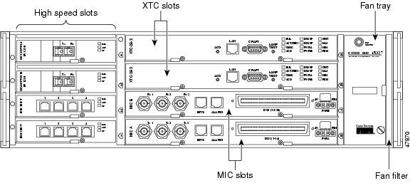
The ONS 15327 has eight card slots numbered 1- 8; four high-speed slots, two Cross-Connect, Timing, and Control (XTC) slots, and two Mechanical Interface card (MIC) slots.
Figure 2 ONS 15327 showing card slot types
All slots are card-ready—when you plug in a card it automatically boots up and becomes ready for service. The cards offer bandwidth in modular increments, making it cost-effective to deploy the system in low-density applications and add bandwidth as needed. The ONS 15327 houses four types of cards: XTC (common control), MIC, Optical, and Ethernet. The XTC and MIC are required to operate the ONS 15327; the Optical and Ethernet cards are high-speed cards.
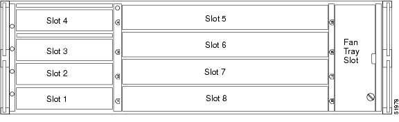
Figure 3 ONS 15327 showing card slot numbers
XTC Card
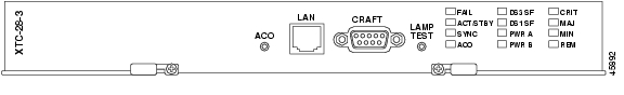
The XTC is the common-control card for the ONS 15327 and contains the electrical tributary circuitry for connecting DS-N traffic. The ONS 15327 provides two XTC cards. The XTC-28-3 card supports 28 DS-1s and three DS-3s.
Figure 4 XTC 28-3 card faceplate
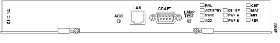
The XTC-14 card supports 14 DS-1s.
Figure 5 XTC-14 card faceplate
Timing and Control Functions
The XTC houses the central intelligence of the ONS 15327 and combines timing, control, and switching functions. It performs:
•
System initialization
•
•
•
•
•
•
•
•
•
The CRIT, MAJ, MIN, and REM alarm LEDs on the XTC faceplate indicate whether a Critical, Major, Minor, or Remote alarm is present anywhere on the ONS 15327 or on a remote node in the network.
The XTC card establishes connections and performs time-division switching (TDS) at the STS-1 level between ONS 15327 traffic cards. You can concentrate or groom low-speed traffic from line cards onto high-speed transport spans and drop low-speed traffic from transport spans onto line cards. The XTC cards provide performance monitoring and protection switching and support STS and VT-level grooming. Slots 5 and 6 are the XTC slots.
In-Service Upgrade
The node name, configuration database, IP address, and system software are stored in the XTC card's non-volatile memory, which allows quick recovery if power or card failures occur. You can upgrade system software without affecting traffic on the ONS 15327 if dual XTC cards are used. The upgrade takes place first on the standby XTC card. The system verifies that the upgrade is successful and switches from the active XTC card running the older release to the upgraded standby XTC card running the newer release. After the switch, the second XTC card undergoes the upgrade. The XTC then loads new software to each line card one at a time. This process is automatic once the cards are inserted.
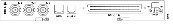
Mechanical Interface Cards
The two MICs, MIC-28-3-A and MIC-28-3-B, provide the physical connection points for the DS-1 and DS-3 interfaces on the XTC cards. They also provide redundant power inputs, inputs and outputs for user-provisionable alarms and controls, and a Building Integrating Timing Supply (BITS) timing input and output.
Each MIC provides 14 DS-1 interfaces for a total of 28 DS-1 interfaces, combined the MICs provide three DS-3 interfaces.
Figure 6 MIC-28-3-A faceplate
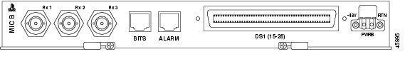
Because the three transmit (Tx) interfaces are on MIC-28-3-A and the three receive (Rx) interfaces are on MIC-28-3-B, you must install both MICs to use the DS-3 capabilities of the ONS 15327.
Figure 7 MIC-28-3-B faceplate
The electrical tributary circuitry for managing individual DS-1s and DS-3s resides in the XTC cards; therefore, you must provision DS-1 and DS-3 circuits using the XTC card.
Each MIC has three input contacts and one output contact. These contacts provide up to six external input alarms and two external output controls that you can provision in CTC. Each MIC also provides connection for one BITS clock input and one BITS clock output. Slots 7 and 8 are the MIC slots.
Optical Cards
The optical cards, OC3 IR 4 1310, OC12 IR 1310, OC12 LR 1550, OC48 IR 1310 and OC48 LR 1550, can reside in any high-speed card slot (1 - 4). You can provision an optical card as part of a UPSR or, in ADM/TM configurations, as either an access tributary or a transport span interface.
The faceplate of both cards has three card-level LED indicators. When illuminated, the red FAIL LED represents a hardware problem, the yellow SF LED represents a signal failure or condition (for example, a loss of frame or a high bit error rate), and the green ACT LED indicates that the card is carrying traffic or is traffic-ready.
OC3 IR 4 1310 Card
The OC3 IR 4 1310 card provides four intermediate-reach, Telcordia-compliant, GR-253 SONET OC-3 interfaces per card. The interface operates at 155.52 Mbps over a single-mode fiber span and supports VT payloads and non-concatenated or concatenated payloads for STS-1 or STS-3c
Figure 8 OC3 IR 4 1310 card faceplate
OC12 IR 1310 Card
The OC12 IR 1310 card provides one intermediate or short-range, Telcordia-compliant, GR-253 SONET OC-12 interface. The interface operates at 622.08 Mbps over a single-mode fiber span and supports VT payloads and non-concatenated or concatenated payloads of STS-1, STS-3C, STS-6C, or STS-12C.
Figure 9 OC12 IR 1310 card faceplate
OC12 LR 1550 Card
The OC12 LR 1550 card provides one long-reach, Telcordia-compliant, GR-253 SONET OC-12 interface per card. The interface operates at 622.08 Mbps over a single-mode fiber span and supports VT payloads and non-concatenated or concatenated payloads for STS-1, STS-3c, STS-6c, or STS-12c
Figure 10 OC12 LR 1550 card faceplate
OC48 IR 1310 Card
The OC48 IR 1310 card provides one intermediate-range, Telcordia-compliant, GR-253 SONET OC-48 interface. Each interface operates at 2488.320 Mbps over a single-mode fiber span and supports VT payloads and non-concatenated or concatenated payloads of STS-1, STS-3C, STS-6C, STS-12C, or STS-48C.
Figure 11 OC48 IR 1310 card faceplate
OC48 LR 1550 Card
The OC48 LR 1550 card provides one intermediate-reach, Telcordia-compliant, GR-253 SONET OC-48 interface per card. Each interface operates at 2488.320 Mbps over a single-mode fiber span and supports VT payloads and non-concatenated or concatenated payloads for STS-1, STS-3c, STS-6c, STS-12c, or STS-48c.
Figure 12 OC48 LR 1550 card faceplate
E10/100-4 Card
The E10/100-4 card provides four IEEE 802.3-compliant, 10/100 interfaces. Each interface supports full-duplex operation for a maximum bandwidth of 200 Mbps per port and 622 Mbps per card. Each port can independently detect the speed of an attached device (auto-senses) and automatically connects at the appropriate speed. The ports auto-configure to operate at either half or full duplex and can determine whether to enable or disable flow control.
Figure 13 Ethernet card faceplate
G1000-2 Card
The G1000-2 provides two IEEE 802.3-compliant, 1000 Mbps ports for high-capacity customer LAN interconnections. Each port supports full-duplex operation for a maximum bandwidth of 2000 Mbps per port. The G1000-2 card uses standard small-form-factor pluggable (SFP) modules for the optical ports. SFPs are input/output devices that p lug into a Gigabit Ethernet port to link the port to the fiber-optic network. Cisco provides two SFP modules: one for short-reach applications and one for long-reach applications. The short-reach model connects to multimode fiber and the long-reach model requires single-mode fiber.
Figure 14 G1000-2 card faceplate
Card Protection
The ONS 15327 provides 1:1 electrical protection and 1+1 optical protection methods. 1:1 electrical protection is pre-provisioned for DS-1 and DS-3 traffic; therefore, only optical cards can operate unprotected. This section describes the protection options and explains protection switching in the ONS 15327. For a description of Ethernet card protection, see the "Spanning Tree Protocol" section.
Electrical Protection
Both XTC cards provide circuitry and electrical protection for DS-1 circuits, but only the XTC-28-3 card provides circuitry and electrical protection for DS-3 circuits. On the ONS 15327, DS-N circuits are automatically protected by a 1:1 protection group, named XTCPROTGRP, which you cannot edit or delete. In 1:1 protection, a working card is paired with an adjacent protect card of the same type, which for the ONS 15327 is two XTC-14 cards (DS-1 circuits protected) or two XTC-28-14 cards (DS-1 and DS-3 circuits protected). If the working card fails, the traffic from the working card switches to the protect card. Electrical protection in the ONS 15327 is non-revertive.
Optical Card Protection
The ONS 15327 supports 1+1 protection to create redundancy for optical cards. With 1+1 protection, one optical port can protect another optical port; therefore, in any two high-speed slots a single working card and a single dedicated protect card of the same type (for example, two OC-48 cards) can be paired for protection. If the working card fails, the protect card takes over. 1+1 span protection can be either revertive or non-revertive.
Linear Automatic Protection Switching
The ONS 15327 supports non-revertive, unidirectional or bidirectional, 1+1 linear automatic protection switching (APS) as the default mode for switching architecture. APS switches the signal from the working card to the protect card automatically when a failure occurs. Non-revertive switching does not switch the signal back automatically when the working card comes back online.
Revertive Switching
The ONS 15327 supports revertive switching. When a failure occurs and APS switches the signal from the working card to the protect card, revertive switching automatically switches the signal back to the working card when the working card comes online. You can easily provision revertive switching using CTC.
Cisco Transport Controller
Cisco Transport Controller (CTC) is a software program that is automatically downloaded from the XTC card to your computer when you connect to the ONS 15327. CTC gives you control of Operation, Administration, Maintenance, and Provisioning (OAM&P) activities for the ONS 15327 using Netscape Navigator or Microsoft° Internet Explorer.
Graphical User Interface
The CTC graphical user interface (GUI), also called the CTC window, provides three primary views, or modes, that include:
•
•
•
The CTC GUI displays text fields with tabs to use for navigation. Some CTC tabs have subtabs, which are used to access subfunctions. From the tabs you can perform all the OAM&P tasks, such as provisioning cards, rings, and circuits; creating protection groups; setting timing parameters; viewing and clearing alarms; provisioning DCCs; backing up and restoring the database; and troubleshooting, including creating diagnostic files and performing loopbacks.
Figure 15 shows the CTC GUI.
Proxy Server Features
The proxy server feature set allows CTC to access ONS 15327s while restricting unauthorized IP connectivity. It can also be used to reduce the amount of network provisioning required for external routers and CTC workstations.
The proxy server feature set consists of the following:
•
•
•
Password Security
CTC employs password complexity rules to enhance login security, including the following rules:
•
Newly created passwords must comply with Telcordia GR-815, which requires that passwords be at least 6 characters long, and contain at least one alphabetic character, one numeric character, and one special character (+, #, or %). CTC will display a warning for previously created passwords that do not meet these requirements but permits the user to continue.
Figure 15 CTC GUI (window) in network view
Circuit Provisioning and Management
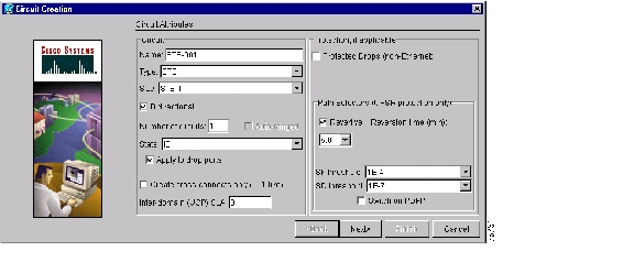
CTC enables automated circuit provisioning across ONS 15327 subnetworks and between ONS 15327s and ONS 15454s, including STS, VT1.5, multiple drop, monitor, and Ethernet circuits. From the CTC GUI, you select a source ONS 15327 and a destination ONS 15327 to create an end-to-end circuit.
Figure 16 Creating circuits with the CTC Circuit Creation dialog box
The ONS 15327 automatically calculates the best path and STS/VT to use between these two nodes. It sets up all the cross-connects in each of the ONS 15327 nodes along the circuit path. You can select the circuit type, bidirectional or unidirectional status, circuit size, and whether path-protected traffic is required. You can also route circuits manually, for example to force traffic onto a particular path. See the "Ethernet" section for a description of Ethernet circuits.
CTC also provides an auto-range feature that prevents you from needing to individually build circuits of the same type. Specify the number of circuits you need, create one circuit, and CTC automatically creates additional sequential circuits.
Auto Range
CTC provides an auto-range feature that automatically creates sequential circuits, which prevents you from needing to individually build circuits of the same type. Specify the number of circuits you need, create one circuit, and CTC automatically creates additional sequential circuits.
Detailed Circuit Map
The detailed circuit map provides an end-to-end view of circuits rather than simply nodes and their spans. Specifically the circuit map shows ports, drops, spans, and selectors for UPSR circuits.
Enhanced Circuit States
State is a user-assigned designation to indicate whether the circuit should be in or out of service. You can assign the following states to circuits and ports:
•
•
•
•
To carry traffic, circuits must have a status of Active and a state of IS, OOS_AINS, or OOS_MT, and the circuit source and destination ports must also be IS, OOS_AINS, or OOS_MT. PARTIAL is appended to a circuit state whenever all circuit cross connects are not in the same state.
Network Element Defaults
You can use the network element (NE) defaults editor to override and configure the default value settings at the port or card level on an ONS 15327. Default values can be changed, exported, imported, and applied using an ASCII text file. Any changes to defaults do not affect previous provisioning; only entities created after you make the change are affected by the new defaults.
Performance Monitoring
CTC displays section, line, and path performance monitoring for optical, electrical, and Ethernet statistics, as defined in GR-253-CORE and GR-820-CORE. For each statistic, you can display 31 previous 15-minute intervals and the current 15-minute interval, as well as the previous 24-hour and current 24-hour interval.
Login Options
The ONS 15327 offers network management flexibility. You can choose to see the login node, nodes with DCC-connectivity to the login node, and nodes that are not DCC-connected to the node.
DCC Connectivity
The ONS 15327 uses SONET data communication channels (SDCCs) for CTC connectivity, automated circuit provisioning, and alarm reporting from remote nodes. Using a node's SDCC, CTC automatically finds and recognizes other ONS 15327s. However, during login you can choose to exclude DCC-connected nodes from auto-discovery, which speeds up login time and reduces clutter on the network map.
Login Node Groups
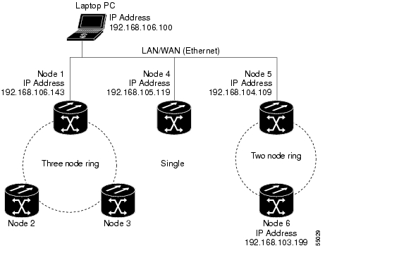
When you log into an ONS 15327 node, only ONS 15327s with DCC connectivity to the node are autodiscovered and displayed in network view. However, you can create a login node group to view and manage ONS 15327s that have an IP connection but no DCC-connectivity to the login node.
For example, in Figure 17, if you logged into Node 1 you would see Node 2 and Node 3 because they have DCC connectivity to Node 1. You would not see Nodes 4, 5, and 6 because DCC connections do not exist. To view all six nodes at once, create a login node group with the IP addresses of Nodes 1, 4, and 5. Those nodes, and all nodes optically connected to them, will display when you log into any node in the group.
Figure 17 Viewing non-DCC nodes using a login node group
CORBA
CTC supports Common Object Request Broker Architecture (CORBA) as a management protocol. The ONS 15327 interface definition language (IDL) is available for customers who want to modify their network management systems to communicate directly with the ONS 15327 using CORBA.
Provisioning Cards
Installed cards in the ONS 15327 are preprovisioned with line and threshold standards that are compliant with Telcordia recommendations. You can change these settings to modify transmission quality.
For electrical (DS-1 and DS-3) connections, you can provision line-transmission settings that include line type, coding length, and status. You can also provision electrical thresholds, including VT1.5 and STS-1 path thresholds.
For optical cards, the provisionable line-transmission settings include, among others, the synchronization status messaging (SSM) feature (see the "Synchronization Status Messaging" section) and the synchronous failure bit error rate (SFBER) level. Optical thresholds include, for example, the protection switching count and protection switching duration.
Customized Network Topology Map
With CTC you can install a custom map for the network view. CTC uses the edge coordinates of the custom map to determine the relative positions of the ONS node icons on the map graphic. The edge coordinates need only be precise enough to place ONS node icons in approximate positions on the map.
To further customize the CTC network view, you can create domains that manage the display of multiple nodes on the network map. The domain feature can reduce the number of icons or group nodes by location.
In-Service Span Upgrades
A span is the optical fiber connection between two ONS 15327 nodes. In a span upgrade, the transmission rate of a span is upgraded from a lower to a higher OC-N signal but all other span configuration attributes remain unchanged. With multiple nodes, a span upgrade is a coordinated series of upgrades on all nodes in the ring or protection group in which traffic carried at a lower OC-N rate is transferred to a higher OC-N. You can perform in-service span upgrades for the following ONS 15327 cards:
•
•
•
To perform a span upgrade, the higher-rate/long-reach optical card must replace the lower-rate/intermediate-reach card in the same slot. If the upgrade is conducted on spans residing in a BLSR, all spans in the ring must be upgraded. The protection configuration of the original lower-rate/intermediate-reach optical card (two-fiber BLSR, UPSR, and 1+1) is retained for the higher-rate/long-reach optical card.
Alarm Collection and Display
The XTCs have faceplate LEDs that alert you to alarms and provide the critical, major, or minor status of the alarm. CTC displays alarms and events on a card or node level for all ONS 15327s in the network. You can also view all alarm messages that appear in CTC using TL1.
CTC Display
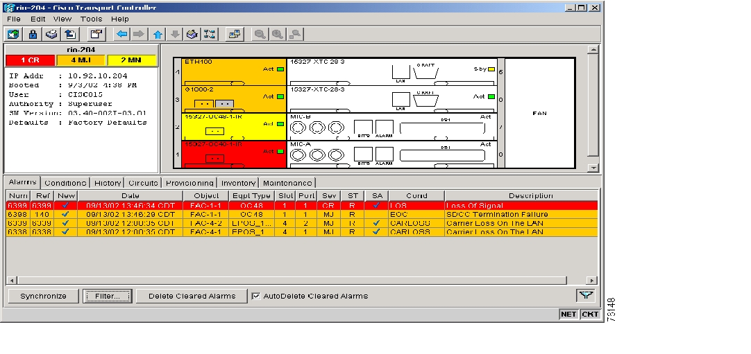
Alarms are displayed in one of five background colors to quickly communicate the alarm severity. You can control the display of current and cleared alarms generated on the node. The alarm and event screens include date, time, severity, reporting node, reporting object, service-affecting status, and a description.
Figure 18 Viewing alarms on the CTC Alarm screen
The history feature displays historical alarm data and also shows events (non-reported activities) that have occurred, such as performance monitoring threshold crossings or protection switching events. The CTC History tab uses subtabs to present two alarm history views:
•
•
Alarm Profiles
The ONS 15327 includes an alarm profile feature. This allows you to change the default alarm severities (for example, change an alarm severity from minor to major) and apply the new severities at the card, port, node, or network level.
Figure 19 Creating alarm profiles with the Alarming tab
Every alarm has a default profile. To create a new profile, clone the default in CTC, rename it, and choose the severity settings for the new profile. Activating and changing profiles are simple procedures in CTC.
Alarm Cutoff
Visual and audible alarms are typically wired to trigger an alarm light or sound at a central alarm collection point when the corresponding contacts are closed. The alarm cutoff (ACO) function stops (turns off) the transmission of the alarm signal to the alarm collection point. To activate the ACO function, press the ACO button on the XTC card faceplate. The ACO button clears all audible alarm indications. The alarm is still active in CTC and needs to be cleared.
With the XTC card-level view in CTC, you can also suppress alarms for a specific DS-1 or DS-3 port. Using CTC you can also suppress alarms for specific Optical and Ethernet ports.
User-Provisionable External Alarms and Controls
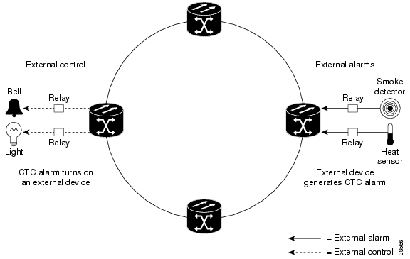
In addition to the standard alarms, the ONS 15327 provides user-provisionable alarms and controls. You can provision up to six external alarm inputs and two external controls. Use external alarms for open doors, temperature sensors, flood sensors, and other environmental conditions. For each alarm you can specify type, severity, and a description. Use external controls, or office alarms, to drive visual or audible devices such as bells and lights. The alarm-triggering conditions for the external controls can be user-defined external input alarms, remote alarms, or severity-based alarms (for example, alarms that trigger when any Major alarm happens).
Figure 20 shows a diagram of the input and output process for external alarms and controls.
Figure 20 External alarm input and output
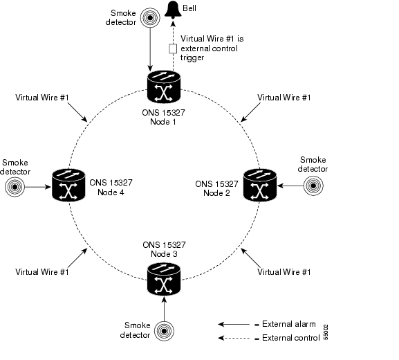
Provisioning external alarms and controls provides a "virtual wires" option that you can use to route alarms and controls from different nodes to one or more alarm collection centers. For example, in Figure 21, smoke detectors are provisioned as external alarms at Nodes 1, 2, 3, and 4. The alarms are assigned to Virtual Wire 1, and Virtual Wire 1 is provisioned as the trigger (control) for an external bell at Node 1.
Figure 21 External alarms and controls using a virtual wire configuration
Reinitialization Tool
You can use the reinitialization (reinit) tool to clear the XTC database and restore customer or factory defaults. This process involves uploading the most recent software package and a blank database. The reinit tool is a .jar file available from the software CD.
Timing
The XTC card performs all system-timing functions for each ONS 15327. The XTC card selects a recovered clock, a BITS, or an internal Stratum 3 reference as the system-timing reference. You can provision any of the clock inputs as a primary or secondary timing source. If you identify two timing references, the secondary reference provides protection. A slow-reference tracking loop allows the XTC card to synchronize to the recovered clock, which provides holdover if the reference is lost.
Timing Parameters
You must set the SONET timing parameters for each ONS 15327. ONS 15327 timing is set to one of two modes: external or line. An externally-timed node derives its timing from a BITS source wired to the BITS input on the MIC. The BITS source, in turn, derives its timing from a Primary Reference Source (PRS) such as a Stratum 1 clock or GPS signal. A line-timed node derives its timing for an incoming optical signal on one of the optical line cards.
Figure 22 shows an example of an ONS 15327 network-timing setup. Node 1 is set to external timing. Two references are set to BITS, and the third reference is set to internal. The BITS output pin on the MIC of Node 3 provides timing to outside equipment, such as a digital access line access multiplexer.
Figure 22 ONS 15327 timing example
Synchronization Status Messaging
Synchronization status messaging (SSM) is a mechanism for managing synchronization (or network timing) in SONET networks. It allows BITS timing sources, nodes, and combinations of the two to exchange information about the quality of timing sources. SSM enables SONET devices such as the ONS 15327 to automatically select the highest quality timing reference and to avoid timing loops (particularly in ring architecture). Synchronization status messages are carried in the S1 byte of the SONET line overhead (Line layer) and as a bit-patterned message in the Extended Super Frame (ESF) datalink of the BITS DS-1. The ONS 15327 supports BITS inputs with or without SSM.
Ethernet
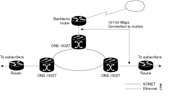
To maximize Ethernet cost effectiveness, the ONS 15327 integrates Ethernet access into the same SONET platform that transports voice traffic. Ethernet over SONET lets service providers augment TDM services with Ethernet, and allows delivery of data traffic over existing facilities. The ONS 15327 supports layer 2 switching and the ability to classify Ethernet traffic as defined in the IEEE 802.1 Q-tag standard. You can switch tagged traffic onto separate SONET STS channels to engineer bandwidth by traffic class. The ONS 15327 can also concentrate Ethernet ports into one or more STS-n circuits to use bandwidth more efficiently.
Figure 23 Ethernet aggregation and transport
Priority Queuing
Networks without priority queuing handle all packets on a first-in-first-out basis. Priority queuing, which is supported by the ONS 15327, reduces the impact of network congestion by mapping Ethernet traffic to different priority levels. The ONS 15327 takes the eight priorities specified in IEEE 802.1Q and maps them to two queues. Q-tags carry priority queuing information through the network.
VLAN Service
The ONS 15327 works with Ethernet devices that do and do not support IEEE 802.1Q tagging. The ONS 15327 supports virtual LANs that provide private network service across a SONET backbone. You can define specific Ethernet ports and SONET STS channels as a VLAN group. VLAN groups isolate subscriber traffic from users outside the VLAN group and keep "outside" traffic from "leaking" into the virtual private network (VPN). Each IEEE 802.1Q VLAN represents a different logical network.
Spanning Tree Protocol
The ONS 15327 operates spanning tree protocol (STP) using the IEEE 802.1D Q-tag standard. STP detects and eliminates network loops. When STP detects multiple paths between any two network hosts, STP blocks ports until only one path exists between any two network hosts. The single path eliminates possible bridge loops. You can enable spanning tree at the Ethernet-port level with a simple CTC procedure.
Single-card and Multicard EtherSwitch
The ONS 15327 supports single-card and multicard EtherSwitch.
When you provision single-card EtherSwitch, each Ethernet card is a single switching entity within the ONS 15327. This option allows STS-12c of bandwidth between two Ethernet circuit points. Single-card EtherSwitch supports one STS-12c, one STS-6c, two STS-3c or six STS-1 circuits. Figure 24 shows a single-card EtherSwitch.
Figure 24 Single-card EtherSwitch
When you provision multicard EtherSwitch, two or more Ethernet cards act as a single layer 2 switch. Multicard EtherSwitch supports one STS-3c circuit or three STS-1 circuits. The bandwidth of the single switch formed by the Ethernet cards matches the bandwidth of the provisioned Ethernet circuit up to STS-3c bandwidth. Figure 25 shows a multicard EtherSwitch.
Figure 25 Multicard EtherSwitch
Ethernet Circuits
The ONS 15327 has three common methods for configuring Ethernet circuits between ONS nodes: a straight-circuit configuration, a shared packet ring configuration, and a hub and spoke configuration. Two nodes usually connect with a straight circuit configuration. More than two nodes usually connect with a shared packet ring or a hub and spoke configuration. You can also manually cross connect individual Ethernet circuits to an STS channel on the ONS 15327 optical interface.
Network Management
The ONS 15327 is compatible with several network management protocols, such as Simple Network Management Protocol (SNMP), Proxy Address Resolution Protocol (ARP), and Open Shortest Path First (OSPF) protocol. If OSPF is not available, static routes can also connect to ONS 15327s through routers. DCC tunneling is provided for interoperability with other vendors' equipment.
Simple Network Management Protocol
Simple Network Management Protocol (SNMP) is an application-layer Internet Protocol (IP) that enables network devices to exchange management information. Network administrators can manage network performance, find and solve network problems, and plan for network growth. The ONS 15327 supports SNMP Version 1 (SNMPv1) and SNMP Version 2c (SNMPv2c); SNMPv2c offers additional protocol operations.
The ONS 15327 uses SNMP to communicate segments of the CTC information model to network management systems, such as HP OpenView Network Node Manager (NNM) or Open Systems Interconnection (OSI) NetExpert. SNMP conveys information required for node-level inventory, fault, and performance management of the ONS 15327 node, and for generic read-only management of DS-1, DS-3, SONET, and Ethernet technologies.
The ONS 15327 incorporates SNMP Remote Monitoring (RMON) to allow network operators to monitor the ONS 15327 E10/100-4 (Ethernet) cards. RMON operates transparently with a network management application, but you can provision RMON alarm thresholds with CTC.
Proxy ARP
Proxy Address Resolution protocol (ARP) enables a LAN-connected gateway ONS 15327 to automatically handle ARP requests for remote non-LAN ONS 15327s connected by a DCC to the gateway ONS 15327. Proxy ARP requires no manual configuration in CTC.
Proxy ARP has a single LAN-connected ONS 15327 stand in (proxy) for remote ONS 15327s. If a device on the LAN sends an ARP request intended for one of the DCC-connected ONS 15327s, the gateway ONS 15327 returns its own MAC address to the LAN device. The LAN device then sends the datagram intended for the remote ONS 15327 to the MAC address of the proxy ONS 15327. The proxy ONS 15327 forwards this data to the remote 15327 using its own ARP table.
Figure 26 Proxy ARP example
Open Shortest Path First
If ONS 15327s are connected to Open Shortest Path First (OSPF) networks, ONS 15327 network information can be automatically communicated across multiple LANs and WANs.
OSPF is a link state Internet routing protocol. Link state protocols use a "hello protocol" to monitor their links with adjacent routers and test their links to their neighbors. Link state protocols advertise their directly-connected networks and their active links. Each link state router captures the link state "advertisements" and puts them together to create a topology of the entire network or area. From this database, the router calculates a routing table by constructing a shortest path tree. Routes are continuously recalculated to capture ongoing topology changes.
You can enable OSPF on the ONS 15327s so that the ONS 15327 topology is sent to OSPF routers on a LAN. Advertising the ONS 15327 network topology to LAN routers eliminates the need to manually provision static routes for ONS 15327 subnetworks.
Static Route Provisioning
The ONS 15327 uses CTC to provision static network routes in ONS 15327 network elements (NEs). Static routes make it possible to have multiple CTC sessions, with different destination IP addresses, on a network of ONS 15327s that all lie on the same subnet. For example, a Network Operations Center (NOC) can remotely monitor an ONS 15327 through CTC at the same time that an on-site employee is logged into an ONS 15327 on the network with a separate CTC session. Static routes also allow workstations to connect to ONS 15327s through routers.
DCC Tunneling
You can tunnel third-party SONET equipment DCCs across ONS 15327 networks. A DCC tunnel is a series of connection points that map a third-party equipment DCC to ONS 15327 DCCs. A DCC tunnel end point is defined by the slot, port, and DCC type. To create a DCC tunnel, you connect the tunnel end points from one ONS 15327 optical port to another. DCC traffic is forwarded transparently, byte-for-byte, across the ONS 15327 network.
Routing Information Protocol, Versions 1 and 2
You can enable Routing Information Protocol (RIP) through CTC. RIP, Version 1 (RIP1) sends updates to a broadcast address so that all devices on the LAN receive and process the messages. RIP, Version 2 (RIP2) reduces unnecessary traffic to hosts that do not receive RIP2 messages by enabling the router to only exchange routing information between connected neighbors.
Network Configurations
The ONS 15327 supports unidirectional path switched rings (UPSRs), bidirectional line switched rings (BLSRs), subtending rings, linear add-drop multiplexer (ADM) supporting 1+1 protection, and mixed configurations. You can also create path-protected mesh networks (PPMNs)
Bidirectional Line Switched Ring
The ONS 15327 supports two-fiber BLSRs with up to 32 ONS 15327 nodes. BLSRs work well for distributed traffic applications, such as interoffice networks.
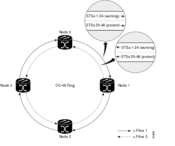
Two-fiber BLSRs allocate half the available fiber bandwidth for protection. In a two-fiber OC-48 BLSR, for example, STSs 1-24 are allocated to working traffic, and STSs 25-48 are allocated for protection. If a break occurs on one fiber, working traffic switches to the protection bandwidth (STSs 25-48) on the other fiber. Working traffic travels in one direction on STSs 1-24 on one fiber, and on STSs 1-24 in the opposite direction on the second fiber. You can create OC-12 and OC-48 two-fiber BLSRs. Figure 27 shows an example of a two-fiber BLSR.
Figure 27 Two-fiber bidirectional line switched ring
Unidirectional Path Switched Ring
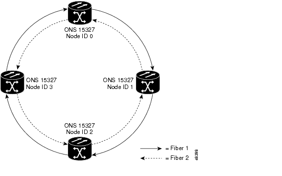
A UPSR is a closed-loop, two-fiber transport architecture that survives cable cuts and equipment failure because it provides duplicate fiber paths for each service. Nodes in the ring are connected using a single pair of optical fibers. Working traffic flows in one direction on the ring and the second fiber provides a protection path flowing in the opposite direction. If a problem occurs in the working traffic path, the receiving node switches to the path coming from the opposite direction.
Services can originate and terminate on the same UPSR or can be passed to an adjacent access or interoffice ring for transport to the service-terminating location. Because each traffic path is transported around the entire ring, UPSRs are best suited for networks where traffic concentrates in one or two locations and is not widely distributed.
Figure 28 shows a basic UPSR configuration. If Node ID 0 sends a signal to Node ID 2, the working signal travels on the working traffic path through Node ID 1. The same signal is also sent on the protect traffic path through Node ID 3. If a fiber break occurs, Node ID 2 switches its active receiver to the protect signal coming through Node ID 3.
Figure 28 Unidirectional path-switched ring example
Subtending Rings
UPSRs and BLSRs can be subtended from one another using one shared node; the node can terminate and groom any one of the following ring combinations:
•
•
•
Subtending rings from an ONS 15327 reduces the number of nodes and cards required, and reduces external shelf-to-shelf cabling. Figure 29 shows an ONS 15327 with multiple subtending rings.
Figure 29 An ONS 15327 with multiple subtending rings
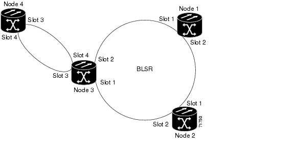
Figure 30 shows a UPSR subtending from a BLSR. In this example, Node 3 is the only node serving both the BLSR and UPSR. Optical cards in Slots 1 and 2 serve the BLSR, and optical cards in Slots 3 and 4 serve the UPSR.
Figure 30 UPSR subtending from a BLSR
Protection Channel Access
With Protection Channel Access (PCA), you can create circuits that use the idle protection bandwidth available on two- and four-fiber BLSRs. PCA circuits are preempted when a protection switch occurs and are restored after the provisioned wait-to-restore time is exceeded.
Linear Add/Drop Multiplexer Mode
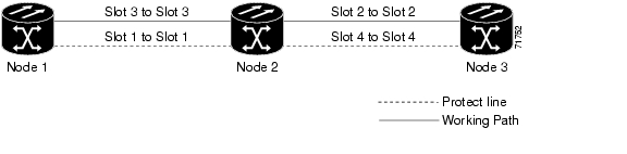
In ADM configuration, intermediate nodes have direct access to eastbound or westbound STS channels along a fiber route, and can connect any STS to any other STS for transport along the network. ADM configurations eliminate the need for costly "back-to-back" terminal configurations and can be enhanced with 1+1 protection for any or all transport spans in the system. Figure 31 shows an ADM configuration.
Figure 31 Linear (point-to-point) ADM configuration
The ONS 15327 supports a full range of line rates as well as TDM and Ethernet/IP access tributary interfaces at every node in ADM configuration. The cross-connect helps to maximize bandwidth allocation by making it possible to map any tributary STS channel to any eastbound or westbound SONET span or to any other access tributary interface.
You can set up an ADM configuration in a few steps using CTC. At turn-up, identify the ONS 15327 network element as part of a linear (non-ring) ADM configuration. The ONS 15327 auto-detects connected network elements through any established transport spans. You can modify default settings as needed.
Terminal Point-to-Point
In terminal point-to-point configuration, one node is physically connected to another node with no intermediate nodes. The add-drop multiplexing feature is usually provided but not used in this configuration.
Figure 32 A linear or UPSR connection between ONS 15327 and ONS 15454 nodes
Path-Protected Mesh Network
ONS 15327 networks give you the option of setting up PPMN. PPMN extends the protection scheme of UPSR from the basic ring configuration to the meshed architecture of several interconnecting rings. Typical UPSR protection creates two separate routes between source and destination nodes on a single UPSR. PPMN does this for source and destination nodes that do not lie on the same ring but link together through a network of meshed connections. When applied to a single ring, PPMN uses the same paths as the UPSR.
PPMN connects the source and destination of a circuit over two diverse paths through a network of single or multiple meshed rings. These two routes form a circuit-level UPSR. The source sends traffic on each of the diverse routes to the destination node, where the destination node uses the active route or switches to the standby route. CTC can automatically route circuits across the PPMN, or you can manually route circuits.
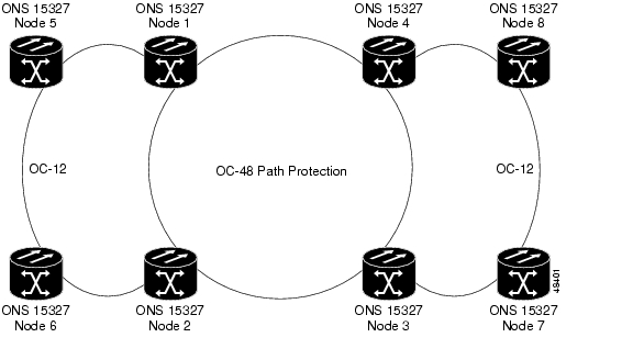
Figure 33 shows an example of a PPMN. In the example, Node 3 is the source and Node 9 is the destination. Automated provisioning automatically determines that the shortest route between the two end nodes passes through Node 8 and Node 7, shown by the dotted line. Cross-connections are automatically created at nodes 3, 8, 7, and 9 to provide a working-traffic route.
If you check the protected circuit box in CTC, PPMN establishes a second unique route between Nodes 3 and 9 and automatically creates cross-connections at nodes 3, 2, 1, 11, and 9, shown by the dashed line. If a signal failure occurs on the primary path, traffic switches to the second, protected circuit path. In this example, Node 9 switches from the traffic coming in from Node 7 to the traffic coming in from Node 11 and service resumes. The switch occurs within 50 milliseconds.
Figure 33 A path-protected mesh network with ONS 15327s and ONS 15454s
Figure 34 PPMN virtual ring
ONS 15327 and ONS 15454 Mixed Configurations
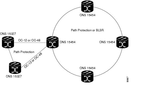
The ONS 15327 can mix BLSR, UPSR, and PPMN configurations in any combination and with ONS 15454s. For example, a BLSR-configured ONS 15327 node can be linked to an ONS 15454 UPSR.
Figure 35 shows an ONS 15327 subtended from an ONS 15454 UPSR or BLSR.
Figure 35 ONS 15327s and ONS 15454s in a mixed configuration
(subtended ring)
TL1
The ONS 15327 supports up to twenty concurrent TL1 sessions that provide the full range of TL1 commands for provisioning and managing ONS 15327 nodes. The Cisco ONS 15454 and Cisco ONS 15327 TL1 Command Guide provides a complete list of commands, including specific sections devoted to ring provisioning and alarms and errors.
TL1 Communication
You can enable TL1 in three ways:
•
•
•
TL1 Gateway and TL1 Test Access
TL1 Gateway enables you to issue TL1 commands to multiple nodes using a single connection. This means you can now provision other nodes in the network from the workstation where you are logged in.
TL1 Test Access enables you to monitor and test circuits. Commands to connect, disconnect, and change the test access (TACC) connections are available.
RJ-45 LAN Connection
The XTC has two built-in interface ports for accessing the ONS 15327. With one RJ-45 interface browser LAN connection you can access the system using a standard browser interface. From the browser interface, you open a VT100 emulation window to enter TL1 commands.
Use port number 2361 to access the ONS 15327 TL1 commands using a Telnet session over a craft interface or RJ-45 LAN connection. The LAN connection is located on the front panel of the XTC card.
ONS 15327 Installation and Hardware
You can mount the ONS 15327 in a 19- or 23-inch, EIA or Telcordia-standard rack and up to 12 ONS 15327s can be used in a single 7-foot rack.You can access the ONS 15327 cards, cables, connectors, power feeds, and fan tray through the front of the ONS 15327 only.
Fan Tray Assembly
The fan tray assembly is a removable drawer that holds fans and fan-control circuitry for the ONS 15327. After you install the fan tray, you do not need to remove it unless a fan failure occurs. The fan tray assembly has an air filter on the right side of the fan tray that you can install and remove by hand to visually inspect.
Figure 36 ONS 15327 fan tray assembly
Cable Management
You can use fiber-optic, coaxial, CHAMP, and twisted-pair cables to connect to the ONS 15327.
The ONS 15327 uses locking cable guides on each side of the shelf assembly to provide efficient cable management and to economize shelf space. The cable guides ensure that the proper bend radius is maintained in the fibers and that all other cables are properly routed. You can easily remove the fiber guides if necessary to create a larger opening, for example, if you need to route copper Ethernet cables out the side.
Figure 37 shows the cable guides routing cables from the front to the sides of the shelf.
Figure 37 ONS 15327 with locking cable guides
Assembly Specifications
•
–
–
–
–
•
–
–
–
•
–
–
•
–
–
–
–
•
–
–
•
•
–
–
–
•
–
–
–
•
Input power: -48V DC
–
–
–
•
–
–
–
–
–
–
–
–
–
–
–
•
–
–
–
–
•
–
–
–
–
–
–
![]()
![]()
![]()
![]()
![]()
![]()
![]()
![]()
Posted: Mon Feb 25 06:00:40 PST 2008
All contents are Copyright © 1992--2008 Cisco Systems, Inc. All rights reserved.
Important Notices and Privacy Statement.