|
|

Table Of Contents
Cisco ME 3400 and Cisco ME 2400 Ethernet Access Switches Getting Started Guide
Equipment That You Supply to Set Up Your Switch
Completing the Initial Configuration
Managing the Switch through the CLI
Rack-Mounting and Switch Port Connections
Installation Warning Statements
Troubleshooting Initial Configuration Setup
Cisco Product Security Overview
Reporting Security Problems in Cisco Products
Obtaining Technical Assistance
Cisco Technical Support & Documentation Website
Definitions of Service Request Severity
Obtaining Additional Publications and Information
Cisco 90-Day Lifetime Hardware Warranty Terms
Getting Started Guide
Cisco ME 3400 and Cisco ME 2400 Ethernet Access Switches Getting Started Guide
INCLUDING LICENSE AND WARRANTY1 About this Guide
This guide provides instructions on how to initially configure your Cisco Metro Ethernet (ME) switch. Also covered are switch management options, basic rack-mounting procedures, port and module connections, power connection procedures, and troubleshooting help.
For additional installation and configuration information, see the Cisco ME switch documentation on Cisco.com. For system requirements, important notes, limitations, open and resolved bugs, and last-minute documentation updates, see the release notes, also on Cisco.com.
When using the online publications, refer to the documents that match the Cisco IOS software version that is running on the switch. Look on the switch rear panel to locate the software version.
You can order printed copies of the manuals from the Cisco.com sites and from the telephone numbers listed in the "Obtaining Documentation" section.
Before you set up your switch, and to see translations of safety warnings, review the warnings that appear in the Regulatory Compliance and Safety Information for the Cisco ME 3400 and Cisco ME 2400 Switches that accompanies this guide.
2 Taking Out What You Need
Follow these steps:
1.
Unpack and remove the switch and the accessory kit from the shipping box.
2.
3.
Equipment That You Supply to Set Up Your Switch
You need to supply this equipment to set up your switch:
•
•
•
Shipping Box Contents
These items ship with your switch, depending on the options that you choose and the type of switch that you order. Some items shown are optional.
3 Initial Setup
To enter the initial IP information when you first set up the switch, you can use the initial configuration dialog (also named the System Configuration Dialog), a command-line interface (CLI)-based application embedded in the flash memory. Initially configuring the switch enables it to connect to local routers and the Internet. You can then access the switch through the IP address for further configuration.
Follow these steps to set up your switch before you run the initial configuration dialog:
Step 1
Obtain and make note of this information from your network administrator before you start the setup program:
•
•
•
•
•
•
Step 2
Using an RJ-45-to-DB-9 adapter cable (console cable), insert the RJ-45 connector into the console port on the front of the switch.
You must supply the console cable if you did not order one with your switch.
This illustration shows the Cisco ME AC switch.
Step 3
Before you power on the switch, start the terminal emulation session so you will be able to see the output display from the power-on self-test (POST). The terminal-emulation software—a PC application such as Hyperterminal or ProcommPlus—makes communication between the switch and your PC or terminal possible.
Step 4
Configure the baud rate and character format of the PC or terminal to match these console port default characteristics:
•
•
•
•
•
Step 5
Connect the switch to a power source.
Typical power consumption = 25 W
Maximum power consumption = 40 W
This illustration shows the Cisco ME DC switch. Connect one end of the supplied DC power cord to the power connector on a switch front panel. Connect the other end of the power cable to a DC outlet.
For detailed instructions to connect to a DC power source, see the "Connecting to DC Power" appendix in the switch hardware installation guide available on cisco.com.
Note
To order spare or replacement DC connectors, use one of these sources:
•
•
Step 6
Power on the switch using either the AC power cord or the DC power connector as appropriate.
Step 7
Wait for the switch to complete the POST.
It might take several minutes for the switch to complete POST.
Step 8
Verify that POST has completed by confirming that the System LED rapidly blinks green. If the switch fails POST, the System LED turns amber.
POST errors are usually fatal. Call Cisco Systems immediately if your switch fails POST.
Step 9
Wait for the switch to complete flash initialization. When you see the prompt Press Return to Get Started!, press Return or Enter.
Press RETURN to get started!Step 10
Go to the "Completing the Initial Configuration" section to continue.
Completing the Initial Configuration
Follow these steps to complete the setup program and create an initial configuration for the switch.
Step 1
After you press Enter or Return after the prompt to start the initial configuration setup program, enter Yes at these three prompts:
Would you like to terminate autoinstall? [yes/no]: yesWould you like to enter the initial configuration dialog? [yes/no]: yesAt any point you may enter a question mark '?' for help.Use ctrl-c to abort configuration dialog at any prompt.Default settings are in square brackets '[]'.Basic management setup configures only enough connectivityfor management of the system, extended setup will ask youto configure each interface on the system.Would you like to enter basic management setup? [yes/no]: yesStep 2
Enter a host name for the switch, and press Return.
The host name is limited to 20 characters. Do not use -n, where n is a number, as the last character in a host name for any switch.
Enter host name [Switch]: host_nameStep 3
Enter an enable secret password, and press Return.
The password can be from 1 to 25 alphanumeric characters, can start with a number, is case sensitive, allows spaces, but ignores leading spaces. The secret password is encrypted and the enable password is in plain text.
Enter enable secret: secret_passwordStep 4
Enter an enable password, and press Return.
Enter enable password: enable_passwordStep 5
Enter a virtual terminal (Telnet) password, and press Return.
The password can be from 1 to 25 alphanumeric characters, is case sensitive, allows spaces, but ignores leading spaces.
Enter virtual terminal password: terminal-passwordStep 6
(Optional) Configure Simple Network Management Protocol (SNMP) by responding to the prompts. You can also configure SNMP later through the command-line interface (CLI). To configure SNMP later, enter no.
Configure SNMP Network Management? [no]: noStep 7
Enter the interface name (physical interface or VLAN name) of the interface that connects to the management network, and press Return. For this release, always enter vlan1 for the interface name at this prompt.
Enter interface name used to connect to themanagement network from the above interface summary: vlan1Step 8
To configure the interface, enter Yes after the prompt, and then enter the switch IP address and subnet mask. Press Return.
The IP address and subnet mask shown on the right are examples.
Configuring interface vlan1:Configure IP on this interface? [yes]: yesIP address for this interface: 10.4.120.106Subnet mask for this interface [255.0.0.0]: 255.0.0.0Step 9
Enter N when the prompt asks you if you would like to enable the switch as a cluster command switch. This switch will be a standalone switch.
Would you like to enable as a
cluster command switch? [yes/no]:
no
You have now completed the initial configuration of the switch, and the switch displays its initial configuration. An example of the output that appears is shown on the right.
The following configuration command script
was created:
hostname switch1enable secret 5 $1$Ulq8$DlA/OiaEbl90WcBPd9cOn1enable password enable_passwordline vty 0 15password terminal-passwordno snmp-server!no ip routing!interface Vlan1no shutdownip address 10.4.120.106 255.0.0.0!interface FastEthernet0/1!interface FastEthernet0/2...<output abbreviated>interface FastEthernet1/0/3!interface GigabitEthernet0/1!interface GigabitEthernet0/2!endStep 10
These choices are displayed:
[0] Go to the IOS command prompt without saving this config.[1] Return back to the setup without saving this config.[2] Save this configuration to nvram and exit.If you want to save the configuration and use it the next time the switch reboots, save it in NVRAM by selecting option 2.Enter your selection [2]:2Make your selection, and press Return.
Step 11
Disconnect the switch from the PC, and install the switch in your production network. See the "Managing the Switch through the CLI" section for information about configuring and managing the switch.
If you need to rerun the initial configuration dialog, see the "Resetting the Switch" section.
Refreshing the PC IP Address
For a dynamically assigned IP address, disconnect the PC from the switch, and reconnect it to the network. The network DHCP server will assign a new IP address to the PC.
For a statically assigned IP address, change it to the previously configured IP address.
4 Managing the Switch through the CLI
After initially setting up and installing the switch in your network, you can enter Cisco IOS commands and parameters through the CLI. Access the CLI either by connecting your PC directly to the switch console port or through a Telnet session from a remote PC or workstation.
Other Management Options
You can use SNMP management applications such as CiscoWorks Small Network Management Solution (SNMS) and HP OpenView to configure and manage the switch. You also can manage it from an SNMP-compatible workstation that is running platforms such as HP OpenView or SunNet Manager.
The Cisco IE2100 Series Configuration Registrar is a network management device that works with embedded CNS agents in the switch software. You can use IE2100 to automate initial configurations and configuration updates on the switch.
See the "Accessing Help Online" section for a list of supporting documentation.
5 Rack-Mounting and Switch Port Connections
This section covers basic 19-inch rack-mounting and switch port connections. For alternate mounting procedures, such as installing the switch in a 23-inch, 24-inch, or a European Telecommunication Standards Institute (ETSI) rack, installing a switch on a wall, and for additional cabling information, see the Cisco ME 3400 Ethernet Access Switch Hardware Installation Guide or the Cisco ME 2400 Ethernet Access Switch Hardware Installation Guide on Cisco.com.
Equipment That You Supply
You need to supply a number-2 Phillips screwdriver to rack-mount the switch. Alternative mounting hardware such as ETSI brackets or other hardware that does not ship with the switch must be supplied separately.
Before You Begin
When determining where to install the switch, verify that these guidelines are met:
Installation Warning Statements
This section includes the basic installation warning statements. Translations of these warning statements and a complete list of warnings that are applicable to this switch appear in the Regulatory Compliance and Safety Information for the Cisco ME 3400 and Cisco ME 2400 Ethernet Access Switches document that shipped with your switch.
Warning
122°F (50°C) Statement 1047
Warning
Warning
Warning
Warning
Warning
Warning
Warning
Warning
Warning
Warning
Warning
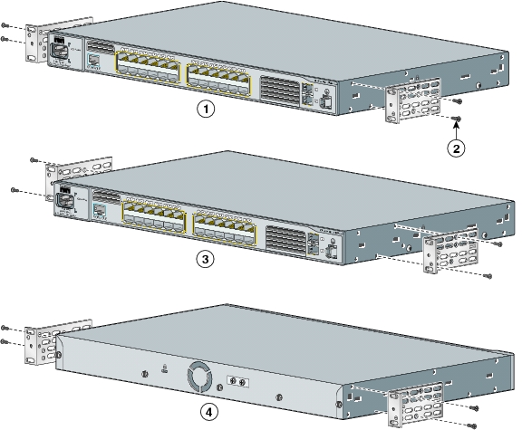
Attaching the Brackets
Use four Phillips flat-head screws to attach the long side of the brackets to the switches in one of three mounting positions.
Rack-Mount the Switch
Use the black Phillips machine screw to attach the cable guide to the left or right bracket. Use the four number-12 Phillips machine screws to attach the brackets to the rack.
Connect to the Switch Ports
This section describes how to connect to the fixed switch ports and to the SFP module ports.
Connect to 10/100 Ports
Follow these steps:
Note
Install the SFP Modules and Connect to the Ports
Note
Follow these steps:
For a list of supported modules, see the release notes on Cisco.com. For detailed instructions on installing, removing, and connecting to SFP modules, see the documentation that came with the SFP module.
Caution
For instructions on using the SFP patch cable, see the "Switch Installation" chapter of the hardware installation guide.
Verify Port Connectivity
After you connect to the switch port, the port LED turns amber while the switch establishes a link. This process takes about 30 seconds, and then the port LED turns green when the switch and the target device have an established link. If the LED is off, the target device might not be turned on, there might be a cable problem, or there might be a problem with the adapter installed in the target device. See the "In Case of Difficulty" section for information about online assistance.
6 In Case of Difficulty
If you experience difficulty, help is available here and on Cisco.com. This section includes initial setup troubleshooting, how to reset the switch, how to access help online, and where to find more information.
Troubleshooting Initial Configuration Setup
If you have problems running the initial configuration dialog:
To order spare or replacement DC connectors, use one of these sources:
•
•
Resetting the Switch
This section describes how to reset the switch by rerunning the initial configuration dialog (System Configuration Dialog). These are reasons why you might want to reset the switch:
•
•
Caution
To reset the switch:
•
•
The switch displays the prompt to run the initial configuration dialog. See the "Initial Setup" section to re-enter the configuration information and setup your switch.
Accessing Help Online
First look for a solution to your problem in the troubleshooting sections of the hardware installation guide or the software configuration guide for your switch on Cisco.com. You can also access the Cisco Technical Support and Documentation website for a list of known hardware problems and extensive troubleshooting documentation, including:
•
•
•
•
•
•
Follow these steps:
1.
2.
3.
or
Product Support > Switches > LAN Switches > Cisco ME 2400 Ethernet Access Switches > Troubleshooting4.
For More Information
For more information about the switch, see these documents on Cisco.com:
•
•
•
•
•
•
•
•
•
•
•
•
•
•
•
•
•
•
7 Obtaining Documentation
Cisco documentation and additional literature are available on Cisco.com. Cisco also provides several ways to obtain technical assistance and other technical resources. These sections explain how to obtain technical information from Cisco Systems.
Cisco.com
You can access the most current Cisco documentation at this URL:
http://www.cisco.com/techsupport
You can access the Cisco website at this URL:
You can access international Cisco websites at this URL:
http://www.cisco.com/public/countries_languages.shtml
Product Documentation DVD
Cisco documentation and additional literature are available in the Product Documentation DVD package, which may have shipped with your product. The Product Documentation DVD is updated regularly and may be more current than printed documentation.
The Product Documentation DVD is a comprehensive library of technical product documentation on portable media. The DVD enables you to access multiple versions of hardware and software installation, configuration, and command guides for Cisco products and to view technical documentation in HTML. With the DVD, you have access to the same documentation that is found on the Cisco website without being connected to the Internet. Certain products also have .pdf versions of the documentation available.
The Product Documentation DVD is available as a single unit or as a subscription. Registered Cisco.com users (Cisco direct customers) can order a Product Documentation DVD (product number DOC-DOCDVD=) from Cisco Marketplace at this URL:
http://www.cisco.com/go/marketplace/
Ordering Documentation
Beginning June 30, 2005, registered Cisco.com users may order Cisco documentation at the Product Documentation Store in the Cisco Marketplace at this URL:
http://www.cisco.com/go/marketplace/
Nonregistered Cisco.com users can order technical documentation from 8:00 a.m. to 5:00 p.m. (0800 to 1700) PDT by calling 1 866 463-3487 in the United States and Canada, or elsewhere by calling 011 408 519-5055. You can also order documentation by e-mail at tech-doc-store-mkpl@external.cisco.com or by fax at 1 408 519-5001 in the United States and Canada, or elsewhere at 011 408 519-5001.
8 Documentation Feedback
You can rate and provide feedback about Cisco technical documents by completing the online feedback form that appears with the technical documents on Cisco.com.
You can send comments about Cisco documentation to bug-doc@cisco.com.
You can submit comments by using the response card (if present) behind the front cover of your document or by writing to the following address:
Cisco Systems
Attn: Customer Document Ordering
170 West Tasman Drive
San Jose, CA 95134-9883We appreciate your comments.
9 Cisco Product Security Overview
Cisco provides a free online Security Vulnerability Policy portal at this URL:
http://www.cisco.com/en/US/products/products_security_vulnerability_policy.html
From this site, you can perform these tasks:
•
•
•
A current list of security advisories and notices for Cisco products is available at this URL:
If you prefer to see advisories and notices as they are updated in real time, you can access a Product Security Incident Response Team Really Simple Syndication (PSIRT RSS) feed from this URL:
http://www.cisco.com/en/US/products/products_psirt_rss_feed.html
Reporting Security Problems in Cisco Products
Cisco is committed to delivering secure products. We test our products internally before we release them, and we strive to correct all vulnerabilities quickly. If you think that you might have identified a vulnerability in a Cisco product, contact PSIRT:
•
An emergency is either a condition in which a system is under active attack or a condition for which a severe and urgent security vulnerability should be reported. All other conditions are considered nonemergencies.
•
In an emergency, you can also reach PSIRT by telephone:
•
•
Tip
Never use a revoked or an expired encryption key. The correct public key to use in your correspondence with PSIRT is the one linked in the Contact Summary section of the Security Vulnerability Policy page at this URL:
http://www.cisco.com/en/US/products/products_security_vulnerability_policy.html
The link on this page has the current PGP key ID in use.
10 Obtaining Technical Assistance
Cisco Technical Support provides 24-hour-a-day award-winning technical assistance. The Cisco Technical Support & Documentation website on Cisco.com features extensive online support resources. In addition, if you have a valid Cisco service contract, Cisco Technical Assistance Center (TAC) engineers provide telephone support. If you do not have a valid Cisco service contract, contact your reseller.
Cisco Technical Support & Documentation Website
The Cisco Technical Support & Documentation website provides online documents and tools for troubleshooting and resolving technical issues with Cisco products and technologies. The website is available 24 hours a day, at this URL:
http://www.cisco.com/techsupport
Access to all tools on the Cisco Technical Support & Documentation website requires a Cisco.com user ID and password. If you have a valid service contract but do not have a user ID or password, you can register at this URL:
http://tools.cisco.com/RPF/register/register.do
Note
Submitting a Service Request
Using the online TAC Service Request Tool is the fastest way to open S3 and S4 service requests. (S3 and S4 service requests are those in which your network is minimally impaired or for which you require product information.) After you describe your situation, the TAC Service Request Tool provides recommended solutions. If your issue is not resolved using the recommended resources, your service request is assigned to a Cisco engineer. The TAC Service Request Tool is located at this URL:
http://www.cisco.com/techsupport/servicerequest
For S1 or S2 service requests or if you do not have Internet access, contact the Cisco TAC by telephone. (S1 or S2 service requests are those in which your production network is down or severely degraded.) Cisco engineers are assigned immediately to S1 and S2 service requests to help keep your business operations running smoothly.
To open a service request by telephone, use one of the following numbers:
Asia-Pacific: +61 2 8446 7411 (Australia: 1 800 805 227)
EMEA: +32 2 704 55 55
USA: 1 800 553-2447For a complete list of Cisco TAC contacts, go to this URL:
http://www.cisco.com/techsupport/contacts
Definitions of Service Request Severity
To ensure that all service requests are reported in a standard format, Cisco has established severity definitions.
Severity 1 (S1)—Your network is "down," or there is a critical impact to your business operations. You and Cisco will commit all necessary resources around the clock to resolve the situation.
Severity 2 (S2)—Operation of an existing network is severely degraded, or significant aspects of your business operation are negatively affected by inadequate performance of Cisco products. You and Cisco will commit full-time resources during normal business hours to resolve the situation.
Severity 3 (S3)—Operational performance of your network is impaired, but most business operations remain functional. You and Cisco will commit resources during normal business hours to restore service to satisfactory levels.
Severity 4 (S4)—You require information or assistance with Cisco product capabilities, installation, or configuration. There is little or no effect on your business operations.
11 Obtaining Additional Publications and Information
Information about Cisco products, technologies, and network solutions is available from various online and printed sources.
•
http://www.cisco.com/go/marketplace/
•
•
•
http://www.cisco.com/go/iqmagazine
or view the digital edition at this URL:
http://ciscoiq.texterity.com/ciscoiq/sample/
•
•
http://www.cisco.com/en/US/products/index.html
•
http://www.cisco.com/discuss/networking
•
http://www.cisco.com/en/US/learning/index.html
12 Cisco 90-Day Lifetime Hardware Warranty Terms
There are special terms applicable to your hardware warranty and various services that you can use during the warranty period. Your formal Warranty Statement, including the warranties and license agreements applicable to Cisco software, is available on Cisco.com. Follow these steps to access and download the Cisco Information Packet and your warranty and license agreements from Cisco.com.
1.
http://www.cisco.com/univercd/cc/td/doc/es_inpck/cetrans.htm
The Warranties and License Agreements page appears.
2.
a.
b.
c.
d.
e.
Note
3.
a.
78-5236-01C0
b.
c.
The Cisco warranty page appears.
d.
You can also contact the Cisco service and support website for assistance:
http://www.cisco.com/public/Support_root.shtml.
Duration of Hardware Warranty
Ninety (90) days.
Replacement, Repair, or Refund Policy for Hardware
Cisco or its service center will use commercially reasonable efforts to ship a replacement part within ten (10) working days after receipt of a Return Materials Authorization (RMA) request. Actual delivery times can vary, depending on the customer location.
Cisco reserves the right to refund the purchase price as its exclusive warranty remedy.
To Receive a Return Materials Authorization (RMA) Number
Contact the company from whom you purchased the product. If you purchased the product directly from Cisco, contact your Cisco Sales and Service Representative.
Complete the information below, and keep it for reference:
Company product purchased from
Company telephone number
Product model number
Product serial number
Maintenance contract number
![]()
![]()
![]()
![]()
![]()
![]()
![]()
![]()
Posted: Thu Nov 17 15:34:42 PST 2005
All contents are Copyright © 1992--2005 Cisco Systems, Inc. All rights reserved.
Important Notices and Privacy Statement.