|
|

Table Of Contents
Connecting the Cisco ONS 15540 ESPx
Preparing for Network Connections
Cleaning the Shelf and Connectors
Connecting the Processor Card to a Network
Cabling Mux/Demux Modules with OSC
Interconnecting Mux/Demux Modules
Connecting Transponder Modules
Direct Connections with Cable Storage Drawers
Mux/Demux Module and Line Card Motherboard Cabling with Cross Connect Drawers
Connecting Mux/Demux Motherboards Land Line Card Motherboards with Cross Connect Drawers
Connecting the 2.5-Gbps Transponder Module
Using MTP Cables for Direct Connections
Cabling 2.5-Gbps Transponder Modules with Cross Connect Drawers
Connecting the 10-GE Transponder Module
Using MTP Cables for Direct Connections
Using Y Cables for 10-GE Direct Connections
Cabling 10-GE Transponder Modules with Cross Connect Drawers
Connecting the Cisco ONS 15540 ESPx
Fiber optic cables are routed to the cable management tray at the bottom of the shelf. The Cisco ONS 15540 ESPx is powered using -48 VDC power. Positive and negative power terminals are accessible on the backplane. You can mount the Cisco ONS 15540 ESPx in a 19-inch or 23-inch rack.
This chapter describes how to connect the Cisco ONS 15540 ESPx to the network and contains the following sections:
•
Preparing for Network Connections
•
•
•
•
•
•
Note
Note
Preparing for Network Connections
When preparing your site for network connections to the Cisco ONS 15540 ESPx shelf, consider the following for each type of interface:
•
•
•
Before installing the component, have all additional external equipment and cables on hand.
Cleaning the Shelf and Connectors
This document contains general cleaning tips and practices not specific to the kit mentioned above.
Be careful with the airflow system when you clean the chassis. If the cleaning process must be done while the system is running, be aware that the airflow system is in operation. Clean the chassis with a damp cloth only and be careful of the following:
•
•
•
Warning
Fiber optic connectors are used to connect two fibers together. When these connectors are used in a communication system, proper connection becomes a critical factor. Fiber optic cable connectors can be damaged by improper cleaning and connection procedures. Dirty or damaged fiber optic connectors can result in not repeatable or inaccurate communication.
Fiber optic connectors differ from electrical or microwave connectors. In a fiber optic system, light is transmitted through an extremely small fiber core. Because fiber cores are often 62.5 microns or less in diameter, and dust particles range from a tenth of a micron to several microns in diameter, dust and any contamination at the end of the fiber core can degrade the performance of the connector interface where the two cores meet. Therefore, the connector must be precisely aligned and the connector interface must be absolutely free of trapped foreign material.
Connector, or insertion, loss is a critical performance characteristic of a fiber optic connector. Return loss is also an important factor. It specifies the amount of reflected light; the lower the reflection the better the connection. The best physical contact connectors have return losses better than -40 dB, although -20 to -30 dB is more common.
Note
The connection quality depends on two factors: the type of connector and the proper cleaning and connection techniques. Dirty fiber connectors are a common source of light loss. Keep the connectors clean at all times and keep the dust cover installed when not in use.
Before installing any type of cable or connector, refer to Cisco ONS 15540 ESPx Cleaning Procedures for Fiber Optic Connections or go to: http://www.cisco.com/univercd/cc/td/doc/product/mels/15540x/15467kit.htm.
When cleaning fiber components, procedures must be followed precisely and carefully with the goal of eliminating any dust or contamination. A clean component connects properly; a dirty component may transfer contamination to the connector, or it may even damage the optical contacts. Inspecting, cleaning, and re-inspecting are critical steps that must be done before making any fiber connection.
As a general rule, whenever there is a significant, unexplained loss of light, clean the connectors.
Caution
The connectors used inside the system have been cleaned by the manufacturer and connected to the adapters in the proper manner. The operation of the system should be error free if the customer provides clean connectors on the application side, follows the previous directions, and ensures the following:
•
•
•
•
Note
Connecting the Processor Card to a Network
Before connecting the processor card to a network, consider the following types of cable required for each interface:
•
•
•
Note
Connecting the Console Port
The console port is a female, DCE (data communications equipment), DB-25 receptacle used for connection to a console terminal or modem.
To connect cables to the console port, follow these steps:
Step 1
Step 2
Step 3
Step 4
Connecting the Auxiliary Port
The auxiliary port supports hardware flow control and modem control and uses the Aux port cable that is shipped with the Cisco ONS 15540 ESPx.
To connect cables to the auxiliary port, follow these steps:
Step 1
Step 2
Step 3
Step 4
Connecting the NME Port
The NME (network management Ethernet) port uses a straight-through RJ-45 cable connector.
To connect cables to the NME port, follow these steps:
Step 1
Step 2
Step 3
Step 4
Connecting Mux/Demux Modules
The Cisco ONS 15540 ESPx fiber optic mux/demux modules use MU connectors. To install fiber optic cables in the Cisco ONS 15540 ESPx, a fiber cable with the corresponding connector type must be connected to the transmit and receive ports on the modules. We recommend that you label the transmit, receive, and the working and protection fibers at each end of the fiber span to avoid confusion with cables that are similar in appearance. Labels are shipped with the system that you can use to do this.
The Cisco ONS 15540 ESPx supports mux/demux modules with front panel optical filter connectors. Each mux/demux module supports a specific band of channels. Every 4-channel band on the mux/demux module has its own MTP connector. A 4-channel mux/demux module has one MTP connector, an 8-channel has two, and a 32-channel mux/demux module has eight.
Caution
Note
Cabling Mux/Demux Modules with OSC
There are three different cables you can use to cable the mux/demux modules. This section describes how to attach and route fiber optic cables between mux/demux modules.
For OSC connections on the motherboard and pass through OSC connections, follow these steps:
Step 1
Step 2
Step 3
Figure 3-1 OSC Cabling
Step 4
Interconnecting Mux/Demux Modules
For mux/demux interconnections, use jumper cables to daisy chain the modules together and follow these steps:
Step 1
Step 2
Connecting PSMs
The PSM (protection switch module) is a shelf replaceable unit, that plugs into any subslot in the mux/demux module. The unit has a front panel set of MU connectors that interface with the trunk fiber in a 1+1 protection scheme. The backside of the module provides an edge connector card, which interfaces with the mux/demux motherboard. The PSM can be connected to the mux/demux module or using a cross-connect drawer direct connections can be made from the ITU trunk cards, the 2.5-Gbps transponder module, or the 10-Gbps uplink card.
To install fiber optic cables in the Cisco ONS 15540 ESPx, a fiber cable with the corresponding connector type must be connected to the transmit and receive ports on the modules. We recommend that you label the transmit, receive, and the working and protection fibers at each end of the fiber span to avoid confusion with cables that are similar in appearance. Labels are shipped with the system.
Warning
Note
Cabling PSMs
To attach and route MU fiber optic cables for PSMs connected to mux/demux modules, follow these steps:
Step 1
Step 2
Step 3
Step 4
Step 5
Step 6
Figure 3-2 Cabling the PSM
Figure 3-3 shows the MU fiber optic connections for a PSM directly connected to a 2.5-Gbps transponder module through the cross-connect drawer.
Figure 3-3 PSM Directly Connected to the 2.5-Gbps Transponder Module
To cable the PSM, follow these steps:
Step 1
Step 2
Step 3
Step 4
Step 5
Connecting Transponder Modules
The Cisco ONS 15540 ESPx fiber optic transponder modules use MU connectors. To install fiber optic cables in the Cisco ONS 15540 ESPx, a fiber cable with the corresponding connector type must be connected to the transmit and receive ports on the modules. We recommend that you label the transmit, receive and the working and protection fibers at each end of the fiber span to avoid confusion with cables that are similar in appearance. Labels are shipped with the system that you can use to do this.
The line card motherboards and the mux/demux motherboards on the Cisco ONS 15540 ESPx connect to each other through the cross connect drawers using the MTP-to-MU breakout cables. The cable has one MTP connector at one end which is plugged either onto the MTP connector at the base of the line card motherboard or onto the MTP connectors on the mux/demux modules.
The motherboards can be installed in any of slots 2 to 5 and 8 to 11; however, the transponder modules in the motherboards, or the channels within the band, must be in increasing order from top to bottom.
To cable the SM and MM transponder module client equipment, follow these steps:
Step 1
Step 2
Step 3
Step 4
Figure 3-4 Cabling Transponder Modules
Step 5
To cable the 2.5-Gbps transponder modules, see the "Connecting the 2.5-Gbps Transponder Module" section
To cable the 10-GE transponder modules, see the "Connecting the 10-GE Transponder Module" section.
Connecting the Cables
Optical components on the Cisco ONS 15540 ESPx can be cabled together in two different ways:
•
•
MTP cables directly connect line card motherboards to optical mux/demux motherboards. One end of each MTP cable connector plugs into a line card motherboard MTP adapter. The other end of the cable plugs into a mux/demux motherboard MTP adapter.
When using the cross connect drawers, the line card motherboards and the mux/demux modules are separately connected to the cross connect panel. One end of a cable plugs into a line card motherboard or a mux/demux motherboard. The connections to the cross connect drawers are made using breakout cables. The cables break out to single fiber cables, which then plug into one end of a high density (octal-MU) adapter. The connections between line card motherboards and mux/demux modules are then made using single fiber cables (terminated in MU connectors at both ends). One end of each of these single fiber cables plugs into an adapter connected to a line card motherboard and the other end into another adapter connected to a mux/demux module.
Final connection between the line card motherboard and the mux/demux module is made using up to sixteen single fiber MU-to-MU cables. The MU connector on one end of the cable plugs into an octal-MU adapter connected to the line card motherboard. The other end of the connector plugs into an adapter connected to the mux/demux module.
Note
Direct Connections with Cable Storage Drawers
When you make direct connections in the Cisco ONS 15540 ESPx, you connect the line card motherboard MTP connections directly to the MTP connections on the mux/demux modules or mux/demux motherboards. This connection requires just one MTP cable storage drawer.
To connect the mux/demux motherboard and line card motherboards directly, follow these steps:
Step 1
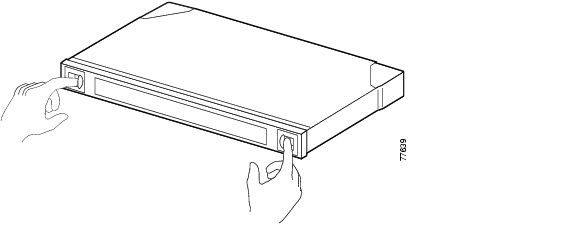
Figure 3-5 Opening the Cable Storage Drawer
Step 2
Figure 3-6 Pulling out the Cable Storage Drawer
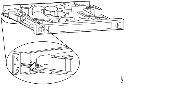
Step 3
Figure 3-7 Locking the Drawer
Step 4
Step 5
Step 6
Step 7
Step 8
Step 9
Figure 3-8 Routing the Cable Storage Drawer
Repeat Steps 1 through 4 to continue cabling the system without the cross connect panel.
Step 10
Figure 3-9 Unlocking the Drawer
Note
Mux/Demux Module and Line Card Motherboard Cabling with Cross Connect Drawers
The line card motherboards and the mux/demux modules on the Cisco ONS 15540 ESPx connect to each other through the cross connect drawers using MTP-to-MU breakout cables. Each breakout cable has an MTP connector on one end and eight individual MU connectors on the other end called breakout cables.
Each cross connect drawer is an 8-channel drawer. To configure a 32-channel system you need four drawers and two cable storage drawers. All MTP and MTP-to-MU breakout cables are pulled out to the left of the chassis and enter the drawers on the left side of the cable storage drawers. They then route out of the right side of the cable storage drawer, enter the cross connect drawers through the right side, and connect to their destination connector. The breakout cables are color coded and should be matched to its corresponding color on the cross connect panel inside the drawer.
The cabling route inside the drawers described in this document is suggested cabling only. Use your own judgement as to how to best route your cable in the drawer according to your configuration and cable length.
To connect cables on the Cisco ONS 15540 ESPx mux/demux modules and line card motherboards using the cross connect drawer, follow these steps:
Step 1
Figure 3-10 Opening the Cable Storage Drawer
Step 2
Figure 3-11 Pulling out the Cable Storage Drawer
Step 3
Figure 3-12 Locking the Drawer
Step 4
Step 5
Step 6
Step 7
Step 8
Step 9
Step 10
Step 11
Figure 3-13 Pulling Up the Cross Connect Panel
Step 12
(See Figure 3-14.)Figure 3-14 Routing the Cross Connect Cables
Step 13
Figure 3-15 Mounting the Transition Box
Step 14
Figure 3-16 Cross Connect Panel
Connecting Mux/Demux Motherboards Land Line Card Motherboards with Cross Connect Drawers
The mux/demux motherboards and the line card motherboards and the on the Cisco ONS 15540 ESPx connect to each other through the cross connect drawers using MTP-to-MU breakout cables. Each breakout cable has an MTP connector on one end and eight individual MU connectors on the other end.
Each cross connect drawer is an 8-channel drawer. To configure a 32-channel system you need four drawers and two cable storage drawers. All MTP and MTP-to-MU breakout cables are pulled out to the left of the chassis and enter the drawers on the left side of the cable storage drawers. They then route out of the right side of the cable storage drawer, enter the cross connect drawers through the right side, and connect to their destination connector.
To connect the mux/demux and transponders in the Cisco ONS 15540 ESPx, use the MU to MU cables and follow these steps:
Step 1
Step 2
Step 3
Figure 3-17 Cross Connect Panel Connections
Step 4
Step 5
For more information about different configurations, see the Cisco ONS 15540 ESPx Planning Guide.
Connecting the 2.5-Gbps Transponder Module
The 2.5-Gbps transponder module requires the following cables:
•
•
•
•
When you make direct connections in the Cisco ONS 15540 ESPx, you connect the line card motherboard MTP connections directly to the MTP connections on the mux/demux modules or mux/demux motherboards. This connection requires just one MTP cable storage drawer.
The line card motherboards and the mux/demux modules on the Cisco ONS 15540 ESPx connect to each other through the cross connect drawers using the MTP-to-8 MU breakout cables. The cable has one MTP connector at one end that is plugged either onto the MTP connector at the base of the line card motherboard or onto the MTP connectors on the mux/demux modules. The cable then runs down into the cross connect drawer and connects to the cross connect panel with the 8 MU cables. The motherboards can be installed in any of slots 2 to 5 and 8 to 11; however, the transponder modules in the line card motherboards, or the channels within the band, must be in increasing order from top to bottom. Figure 3-18 shows an example of the transponder modules (TSP) to wavelength connection through the cross connect panel.
Figure 3-18 Transponder Module to Wavelength Connection
The Cisco ONS 15540 ESPx allows channels from different bands in the same slot. With the cross connect drawer, the system allows for use of an application where it is possible to use only certain channels in a given node. Figure 3-19 shows the connections you would make if you wanted to use only channels 1, 5, and 9.
Figure 3-19 Channels from Different Bands
Band A 0 to 2 would extend from your mux/demux module. Using your cross connect drawer, channels 1, 5, and 9 would extend to your transponder modules. Use the MU-to-MU connectors to connect from band A to channels 1, 5, and 9.
Using MTP Cables for Direct Connections
To connect the mux/demux motherboards and line card motherboards directly using an MTP-to-MTP cable, follow these steps:
Step 1
Figure 3-20 Opening the Cable Storage Drawer
Step 2
Figure 3-21 Pulling Out the Cable Storage Drawer
Step 3
Figure 3-22 Locking the Drawer
Step 4
Step 5
Step 6
Step 7
Step 8
Step 9
Figure 3-23 Routing the Cable Storage Drawer
Repeat Steps 1 through 4 to continue cabling the system without the cross connect panel.
Step 10
Figure 3-24 Unlocking the Drawer
Note
Cabling 2.5-Gbps Transponder Modules with Cross Connect Drawers
To connect cables on the Cisco ONS 15540 ESPx 2.5-Gbps transponder modules using the cross connect drawer, follow these steps:
Step 1
Figure 3-25 Opening the Cable Storage Drawer
Step 2
Figure 3-26 Pulling out the Cable Storage Drawer
Step 3
Figure 3-27 Locking the Drawer
Step 4
Step 5
Step 6
Step 7
Step 8
Step 9
Step 10
Step 11
Figure 3-28 Pulling Up the Cross Connect Panel
Step 12
(See Figure 3-29.)Figure 3-29 Routing the Cross Connect Cables
Step 13
Figure 3-30 Mounting the Transition Box
Step 14
Figure 3-31 Cross Connect Panel
Step 15
To connect the mux/demux motherboards to the line card motherboards, see the "Connecting Mux/Demux Motherboards Land Line Card Motherboards with Cross Connect Drawers" section.
Connecting the 10-GE Transponder Module
The 10-GE transponder module requires the following cables:
•
•
•
•
When you make direct connections in the Cisco ONS 15540 ESPx, you connect the line card motherboard MTP connections directly to the MTP connections on the mux/demux modules or mux/demux motherboards. This connection requires just one MTP cable storage drawer. There are two different cables you can use for direct connections depending on your configuration:
•
•
The line card motherboards and the mux/demux motherboards on the Cisco ONS 15540 ESPx connect to each other through the cross connect drawers using the MTP-to-MU breakout cables. The cable has one MTP connector at one end that usually is plugged either onto the MTP connector at the base of the line card motherboard or onto the MTP connectors on the mux/demux modules.
The motherboards can be installed in any of slots 2 to 5 and 8 to 11; however,, the transponder modules in the line card motherboards, or the channels within the band, must be in increasing order from top to bottom.
Note
Using MTP Cables for Direct Connections
To connect the mux/demux motherboards and line card motherboards directly using an MTP-to-MTP cable, follow these steps:
Step 1
Figure 3-32 Opening the Cable Storage Drawer
Step 2
Figure 3-33 Pulling out the Cable Storage Drawer
Step 3
Figure 3-34 Locking the Drawer
Step 4
Step 5
Step 6
Step 7
Step 8
Step 9
Figure 3-35 Routing the Cable Storage Drawer
Repeat Steps 1 through 4 to continue cabling the system without the cross connect panel.
Step 10
Figure 3-36 Unlocking the Drawer
Note
Using Y Cables for 10-GE Direct Connections
To connect the mux/demux motherboards and line card motherboards directly using a y cable, follow these steps:
Step 1
Figure 3-37 Opening the Cable Storage Drawer
Step 2
Figure 3-38 Pulling out the Cable Storage Drawer
Step 3
Figure 3-39 Locking the Drawer
Step 4
Step 5
Step 6
Step 7
Step 8
Step 9
Figure 3-40 Routing the Cable Storage Drawer
Repeat Steps 1 through 4 to continue cabling the system without the cross connect panel.
Step 10
Figure 3-41 Unlocking the Drawer
Note
Cabling 10-GE Transponder Modules with Cross Connect Drawers
To connect cables on the Cisco ONS 15540 ESPx 10-GE transponder modules using the cross connect drawer, follow these steps:
Step 1
Figure 3-42 Opening the Cable Storage Drawer
Step 2
Figure 3-43 Pulling out the Cable Storage Drawer
Step 3
Figure 3-44 Locking the Drawer
Step 4
Step 5
Step 6
Step 7
Step 8
Step 9
Step 10
Step 11
Figure 3-45 Pulling up the Cross Connect Panel
Step 12
(See Figure 3-46.)Figure 3-46 Routing the Cross Connect Cables
Step 13
Figure 3-47 Mounting the Transition Box
Step 14
Figure 3-48 Cross Connect Panel
Step 15
The mux/demux expects the channels within the band boundary in a certain order, lowest to highest. Since the 10-Gbps line card motherboard holds only two 10-GE transponder modules, the module in subslot 0 always uses the first channel and the module in subslot 1 uses the second channel within the four possible channels.
When you connect the MU connectors from the mux/demux motherboard to the 10-Gbps line card motherboard on the cross connect panel, you must know what channel the 10-GE transponder module represents and cross connect to the appropriate location.
For example, (see Figure 3-49) if the 10-GE transponder module installed in subslot 0 represents channel seven, then it corresponds with the third channel within band B (5, 6, 7, 8). You would use the MU connectors to connect the Tx and Rx of the subslot 0 line card motherboard port to the Tx and Rx of the third channel on the mux/demux motherboard port on the cross connect panel. If the 10-GE transponder module were installed in subslot 1, you would connect the Tx and Rx of the subslot 1 line card motherboard port to the Tx and Rx of the third channel on the mux/demux motherboard port on the cross connect panel.
Figure 3-49 10-GE Transponder to Channel Connection
To connect the mux/demux motherboards to the line card motherboards, see the "Connecting Mux/Demux Motherboards Land Line Card Motherboards with Cross Connect Drawers" section.
![]()
![]()
![]()
![]()
![]()
![]()
![]()
![]()
Posted: Tue Mar 8 16:34:30 PST 2005
All contents are Copyright © 1992--2005 Cisco Systems, Inc. All rights reserved.
Important Notices and Privacy Statement.