|
|

Table Of Contents
Configuring ESCON Aggregation Card Interfaces
About ESCON Signal Aggregation Support
Configuring ESCON Aggregation Card Interfaces
Displaying the ESCON Aggregation Card Interface Configuration
About Latency and Transmit Buffers
Configuring Transmit Buffer Size
Displaying Transmit Buffer Configuration
Displaying the Cross Connection Configuration
Displaying the Alarm Threshold Configuration
About Performance History Counters
Displaying Performance History Counters
Configuring ESCON Aggregation Card Interfaces
This chapter describes how to configure the interfaces on 10-port ESCON aggregation cards.
This chapter includes the following sections:
•
About ESCON Signal Aggregation Support
•
•
•
•
•
•
•
About ESCON Signal Aggregation Support
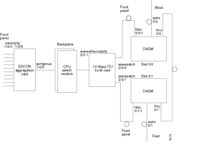
The ESCON aggregation card aggregates up to ten ESCON data streams into a single 2.5-Gbps signal, which is transmitted through the switch fabric to a 2.5-Gbps ITU trunk card, 10-Gbps ITU trunk card, 10-Gbps ITU tunable trunk card, or 10-Gbps uplink card. The ESCON aggregation card can be populated with up to ten SFP (small form-factor pluggable) optics.
Figure 4-1 shows the path of an ESCON signal through the Cisco ONS 15530.
Figure 4-1 Interface Model for ESCON Aggregation
To configure ESCON support on the Cisco ONS 15530, perform the following steps:
Step 1
Step 2
Step 3
Step 4
Step 5
Configuring ESCON Aggregation Card Interfaces
The ESCON aggregation card has two types of interfaces: ten esconphy interfaces on the client side and one portgroup interface on the trunk side. The primary feature to configure on the ESCON aggregation card is the in-band message channel flow identifier. The in-band message channel provides an encapsulation that uniquely identifies an ESCON signal when it is aggregated with the other ESCON signals.
To configure the ESCON aggregation card interfaces, perform the following steps, starting in global configuration mode:
Step 1
Switch(config)# interface esconphy slot/0/port
Switch(config-if)#
Specifies an interface to configure and enters interface configuration mode.
Step 2
Switch(config-if)# cdl flow identifier number
Configures the in-band message channel flow identifier. The range is 0 to 174.
Note
Caution
Step 3
Switch(config-if)# laser control forward enable
Enables forward laser control on the interface. The default for esconphy interfaces is enabled.
When FLC is enabled on the interface where the receive fault (loss of light or loss of synchronization) occurs, the peer Escon port shuts down its laser toward the client device (even if FLC is not enabled). This card uses end-to-end FLC (E2EFLC).
For more information on FLC, see the "About Laser Shutdown" section on page 8-13.
Step 4
Switch(config-if)# no shutdown
Enables the interface.
Step 5
Switch(config-if)# exit
Switch(config)#
Returns to global configuration mode.
Repeat Step 1 through Step 5 for the other esconphy interfaces on the ESCON aggregation card.
Step 6
Switch(config)# interface portgroup slot/0/0
Switch(config-if)#
Specifies an interface to configure and enters interface configuration mode.
Step 7
Switch(config-if)# cdl flow identifier reserve group-name
Configures the in-band message channel flow identifiers for all ten esconphy interfaces even if the SFPs are not populated. This step is required if the aggregated ESCON signal mixes with GE traffic on a 10-Gbps ITU trunk card or a 10-Gbps ITU tunable trunk card.
Note
Caution
Note
Example
The following example shows how to configure ESCON aggregation card interfaces:
Switch(config)# interface esconphy 10/0/0Switch(config-if)# cdl flow identifier 100Switch(config-if)# no shutdownSwitch(config-if)# exitDisplaying the ESCON Aggregation Card Interface Configuration
To display the configuration of ESCON aggregation card interfaces, use the following EXEC commands:
Examples
The following example shows how to display the configuration of an esconphy interface:
Switch# show interfaces esconphy 7/0/0EsconPhy7/0/0 is administratively down, line protocol is downForward laser control:OnThreshold monitored for:NoneReceived Frames:0Transmit Frames:0Code violation and running disparity error count( 8b10b cvrd):0CRC error count:0Egress Packet Sequence error count:0Egress Packet Indicated error count:05 minute input rate 0 bits/sec, 0 frames/sec5 minute output rate 0 bits/sec, 0 frames/secTransmit Buffer size is 16 bytesHardware is escon_phy_portThe following example shows how to display the configuration of a portgroup interface:
Switch# show interfaces portgroup 10/0/0devt_ham_03/11#sh in portgroup 10/0/0Portgroup10/0/0 is up, line protocol is upTransmit Packets: 883067943Received Packets: 887268737Code violation and running disparity error count(cvrd): 247499080Number of times SF threshold exceeded: 0Number of times SD threshold exceeded: 0CRC error count: 3Number of times SF threshold exceeded: 0Number of times SD threshold exceeded: 0CDL HEC error count: 0Number of times SF threshold exceeded: 0Number of times SD threshold exceeded: 0SII Mismatch error count: 0ESCON Protocol Mismatch error count: 0Hardware is portgroupThe following example shows how to display the flow identifiers on the system:
Switch# show cdl flow identifierInterface FlowIdentifier------------ ----------Esco8/0/0 80Esco8/0/1 81Esco8/0/2 82Esco8/0/3 83Esco8/0/4 84Esco8/0/5 85Esco8/0/6 86Esco8/0/7 87Esco8/0/8 88Esco8/0/9 89Esco10/0/0 100Esco10/0/1 255Esco10/0/2 255Esco10/0/3 255Esco10/0/4 255Esco10/0/5 255Esco10/0/6 255Esco10/0/7 255Esco10/0/8 255Esco10/0/9 255About Latency and Transmit Buffers
The ESCON aggregation card adds latency to the transmission of ESCON traffic. Table 4-1 shows the various configurations on the transmitting node and the ESCON latency values.
Note
Table 4-1 Latency Values for ESCON Aggregation Cards
ESCON only
8.5 Βs
ESCON and FC/FICON on the same 10-Gbps ITU trunk card or 10-Gbps ITU tunable trunk card
8.5 Βs
ESCON and GE only on the same 10-Gbps ITU trunk card or 10-Gbps ITU trunk card
10 Βs
12.5 Βs
17 Βs
1 The latency values are based on configuration of correct transmit buffer sizes as described in Table 4-2.
A transmit buffer on the receiving node compensates for the packet jitter effects due to service multiplexing on the trunk. You must correctly configure the size of this transmit buffer to ensure that no buffer underflow or overflow occurs.
Configuring Transmit Buffer Size
To accommodate this latency on the receiving node, perform the following steps, starting in global configuration mode:
Table 4-2 provides the transmit buffer settings for various configurations.
Example
The following example shows how to configure the transmit buffer size on the receiving node:
Switch(config)# interface esconphy 3/0/2Switch(config-if)# shutdownSwitch(config-if)# tx-buffer size 168Switch(config-if)# no shutdownDisplaying Transmit Buffer Configuration
To display the transmit buffer configuration of an esconphy interface, use the following EXEC command:
Example
The following example shows how to display the transmit buffer configuration:
Switch# show interfaces esconphy 3/0/0EsconPhy3/0/0 is administratively down, line protocol is downForward laser control: OnConfigured threshold Group(s): allThreshold monitored for: CRCSF set value: 10e-8 (2 in 1 secs)SD set value: 10e-9 (1 in 5 secs)Received Frames: 0Transmit Frames: 0Code violation and running disparity error count( 8b10b cvrd): 0CRC error count: 0Number of times SF threshold exceeded: 0Number of times SD threshold exceeded: 0Egress Packet Sequence error count: 0Egress Packet Indicated error count: 05 minute input rate 0 bits/sec, 0 frames/sec5 minute output rate 0 bits/sec, 0 frames/secTransmit Buffer size is 168 bytes
Hardware is escon_phy_portAbout Cross Connections
The client signal follows a path of interface optical cross connections through the Cisco ONS 15530. Figure 4-2 shows an example of cross connections. Knowing the path of a signal through the shelf helps with system management and troubleshooting.
Figure 4-2 Optical Cross Connection Example For ESCON Aggregation Card Interfaces
Configuring Cross Connections
The aggregated signal from the ESCON aggregation cards passes through the switch fabric to the 2.5-Gbps ITU trunk card, 10-Gbps ITU trunk card, 10-Gbps ITU tunable trunk card or the 10-Gbps uplink card. To establish a cross connection through the switch fabric, perform the following steps, beginning in global configuration mode:
Switch(config)# connect interface1 interface2
Creates a cross connection between two interfaces through the switch fabric.
Caution
Example
The following example shows how to configure a cross connection between an ESCON aggregation card and a 2.5-Gbps ITU trunk card:
Switch(config)# connect portgroup 2/0/0 waveethernetphy 3/0The following example shows how to configure a cross connection between an ESCON aggregation card and a 10-Gbps ITU trunk card:
Switch(config)# connect portgroup 2/0/0 waveethernetphy 3/0.1The following example shows how to configure a cross connection between an ESCON aggregation card and a 10-Gbps uplink card:
Switch(config)# connect portgroup 2/0/0 tengigethernetphy 3/0.1Displaying the Cross Connection Configuration
To display the cross connection configuration, use the following privileged EXEC command:
show connect [edge | intermediate [sort-channel | interface interface]]
Displays the signal cross connection configuration through the system.
Example
The following example shows the cross connections within a system for an ESCON signal:
Switch# show connectIndex Client Intf Trunk Intf Kind C2TStatus T2CliStatus----- --------------- --------------- ----------- ---------- ---------15 Port3/0/0 WaveE8/0.1 Provisioned Up UpAbout Alarm Thresholds
You can configure thresholds on the ESCON aggregation card interfaces that issue alarm messages to the system if the thresholds are exceeded.
Every second the monitoring facility updates the counters that correspond to the alarm thresholds. When the signal degrades, or fails entirely, the system issues alarms to the console. These alarms can help isolate failures in the system and in the network. Signal degrade and signal failure are indicators of signal quality based on the signal data stream. Signal degrade is reported when the number of errors reported per second is more than the signal degrade threshold. Signal failure is reported when the number of errors per second is more than the signal failure threshold.
You can configure more than one threshold list on an interface. The threshold lists cannot have overlapping counters so that only one counter is set for the interface. Also, the threshold list name cannot begin with the text string "default" because it is reserved for use by the system.
Configuring Alarm Thresholds
To configure alarm thresholds on the ESCON aggregation card, 2.5-Gbps ITU trunk card, 10-Gbps ITU trunk card, 10-Gbps ITU tunable trunk card, and 10-Gbps uplink card interfaces, perform the following steps, beginning in global configuration mode:
Step 1
Switch(config)# threshold-list name
Switch(config-t-list)#
Creates or selects the threshold list to configure and enters threshold list configuration mode.
Note
Step 2
Switch(config-t-list)# notification-throttle timer seconds
Configures the SNMP notification timer. The default value is 5 seconds. (Optional)
Step 3
Switch(config-t-list)# threshold name {cvrd | cdl hec | crc | sonet-sdh section cv | tx-crc} {failure | degrade} [index value]
Switch(config-threshold)#
Specifies a threshold type to modify and enters threshold configuration mode.
Step 4
Switch(config-threshold)# value rate value
Specifies the threshold rate value. This value is the negative power of 10 (10-n).
Step 5
Switch(config-threshold)# description text
Specifies a description of the threshold. The default value is the null string. (Optional)
Step 6
Switch(config-threshold)# exit
Switch(config-t-list)#
Returns to threshold list configuration mode.
Repeat Step 3 through Step 6 to configure more thresholds in the threshold list.
Step 7
Switch(config-t-list)# exit
Switch(config)#
Returns to global configuration mode.
Step 8
Switch(config)# interface interface
Switch(config-if)#
Selects the interface to configure and enters interface configuration mode.
Step 9
Switch(config-if)# threshold-group name
Configures the threshold list on the interface.
Note
Table 4-3 lists the threshold error rates in errors per second for ESCON signals.
Table 4-3 Threshold Values for Monitored Rates for ESCON Signals in Errors Per Second
3
19999
20000
4
19999
20000
5
1999
2000
6
199
200
7
20
20
8
2
2
9
0.2
0.2
Example
The following example shows how to create an alarm threshold list and configure that list for ESCON aggregation card interfaces:
Switch# configure terminalSwitch(config)# threshold-list escon-countersSwitch(config-t-list)# threshold name crc degradeSwitch(config-threshold)# value rate 9Switch(config-threshold)# exitSwitch(config-t-list)# threshold name crc failureSwitch(config-threshold)# value rate 7Switch(config-threshold)# exitSwitch(config-t-list)# exitSwitch(config)# interface esconphy 3/0/0Switch(config-if)# threshold-group escon-countersDisplaying the Alarm Threshold Configuration
To display the configuration of a threshold list and the threshold group for an esconphy interface, use the following EXEC commands:
show threshold-list [name]
Displays the threshold group configuration.
show interfaces {esconphy slot/subcard/slot}
Displays the interface configuration.
Examples
The following example shows how to display the configuration of a threshold group:
Switch# show threshold-list escon-countersThreshold List Name: escon-countersNotification throttle timer : 5 (in secs)Threshold name : CRC Severity : DegradeValue : 10e-9APS Trigger : Not setThreshold name : CRC Severity : FailureValue : 10e-7APS Trigger : Not setThe following example shows how to display the threshold group information for an interface:
Switch# show interfaces esconphy 3/0/0EsconPhy3/0/0 is up, line protocol is upSignal quality: GoodForward laser control: OffConfigured threshold Group: escon-countersThreshold monitored for: CRCSF set value: 10e-7 (20 in 1 secs)SD set value: 10e-9 (1 in 5 secs)Received Frames: 0Transmit Frames: 0Code violation and running disparity error count(cvrd): 0Number of times SF threshold exceeded: 0Number of times SD threshold exceeded: 0CRC error count: 0Number of times SF threshold exceeded: 0Number of times SD threshold exceeded: 0Egress Packet Sequence error count: 0Egress Packet Indicated error count: 05 minute input rate 0 bits/sec, 0 frames/sec5 minute output rate 0 bits/sec, 0 frames/secHardware is escon_phy_portAbout Performance History Counters
Cisco ONS 15530 supports 15 minute based performance history counters. You can use the performance history counters to track the performance of the Cisco ONS 15530 interfaces.
There are three types of performance history counters: current, 15-minute history, and 24-hour. Cisco ONS 15530 uses these counters to store the performance data for the following time periods:
•
•
•
When the Cisco ONS 15530 system boots up, a continuously incrementing current counter is started. At the end of 15 minutes, this current counter is converted to a static 15-minute history counter with an interval number 1, and a new current counter is started with an interval number 2.
This process continues for 24 hours, by the end of which, ninety six 15-minute history counters are created. After the creation of the ninety sixth 15-minute history counter, a new 24-hour counter is created along with a current counter that has an interval number 1. The 24-hour counter has the aggregated data of all the ninety six 15-minute history counters.
The 15-minute history counters that are created thereafter overwrite the existing set of ninety six 15-minute history counters, in the order they were created. Again, after the creation of the ninety sixth 15-minute history counter, the contents of the existing 24-hour counter are overwritten with new values. This entire process continues in a cyclic fashion.
Note
The performance history counters synchronize periodically from the primary CPU switch module to the standby CPU switch module enabling the system to preserve the performance data across a CPU switch module switchover.
Note
Displaying Performance History Counters
To display the performance history counters, use the following EXEC commands:
show performance current [interface]
Displays the current counter for the specified interface1 .
show performance history [interface] [interval number]
Displays the 15-minute history counter for the specified interface and interval number1.
show performance 24-hour [interface]
Displays the 24-hour counter for the specified interface1.
1 If you do not specify the interface or interval number, the performance history counters for all interfaces or interval numbers are displayed.
To clear and reset all performance history counters, use the following EXEC command:
clear performance history [interface]
Clears the performance history counters for the specified interface.
Examples
The following example shows how to display the current counter for an esconphy interface:
Switch# show performance current esconphy 9/0/0Current 15 minute performance register--------------------------------------Interface : EsconPhy9/0/0Interval Number : 24Elapsed Time(seconds) : 272Valid Time(seconds) : 272Received Frames : 72868010Transmit Frames : 72868009CRC Error count : 370Code violation and running disparity error count : 4Egress Packet Sequence error count : 0Egress Packet Indicated error count : 3The following example shows how to display the 15-minute history counter for an esconphy interface:
Switch# show performance history esconphy 9/0/0 8515 minute performance history register--------------------------------------Interface : EsconPhy9/0/0Interval Number : 85Total Time(seconds) : 900Valid Time(seconds) : 900Received Frames : 240112821Transmit Frames : 240120239CRC Error count : 78Code violation and running disparity error count : 0Egress Packet Sequence error count : 0Egress Packet Indicated error count : 0The following example shows how to display the 24-hour counter for a portgroup interface:
Switch# show performance 24-hour portgroup 9/0/024 hour performance register----------------------------Interface : Portgroup9/0/0Total Time(seconds) : 86400Valid Time(seconds) : 86400Transmit Packets : 209633686142Received Packets : 209662107547Code violation and running disparity error count : 795368336CRC error count : 8640CDL HEC error count : 0SII Mismatch error count : 0Protocol Mismatch error count : 0The CRC error count is fetched by the Tx CRC MIB object, and the SII mismatch error count is fetched by the Rx SII mismatch idle frames MIB object for the portgroup interface of the 10-port ESCON aggregation card.
![]()
![]()
![]()
![]()
![]()
![]()
![]()
![]()
Posted: Wed Apr 26 03:07:45 PDT 2006
All contents are Copyright © 1992--2006 Cisco Systems, Inc. All rights reserved.
Important Notices and Privacy Statement.