|
|

This chapter describes how to configure and manage your network with the management console. Table 5-1 shows the default settings for many parameters and the menus you use to set them.
| Default Setting | Management Console Menu | |
|---|---|---|
| Switching mode | FastForward | "System Configuration" in this chapter |
| Spanning-Tree Protocol | Enabled | "Spanning-Tree Configuration" in this chapter |
| Addressing security | Disabled | "Port Addressing" in this chapter |
| VLAN configuration | All ports belong to VLAN1 | "VLAN Configuration" in this chapter |
| Port monitoring | Disabled | "Monitoring Configuration" in this chapter |
| Flooding unknown unicast packets | Enabled | "Port Addressing" in this chapter |
| Flooding unregistered multicast packets | Enabled | "Port Addressing" in this chapter |
| Full duplex for FastMate 1-port 100Base-T modules | Disabled | "Port Configuration" in this chapter |
| Assign IP address to Catalyst 2100 | 0.0.0.0 | "IP Configuration" in this chapter |
| Define trap manager | 0.0.0.0 | "Network Management (SNMP) Configuration" in this chapter |
| Action upon address violation | Suspend | "System Configuration" in this chapter |
When connected to a terminal or modem, Catalyst 2100 must be configured to the same baud rate and character format as the terminal or modem. Although the Match Baud Rate option (autobaud) matches the baud rate when Catalyst 2100 is answering an incoming call, Catalyst 2100 does not change from its configured rate when it is dialing out. Also, Catalyst 2100 only matches a rate lower than its configured rate. When it completes a call and disconnects, Catalyst 2100 always returns to the last configured baud rate.
The following are the default RS-232 characteristics for Catalyst 2100:
These characteristics can be changed using the procedure in the section "RS-232 Interface Configuration" in this chapter. If you are using SNMP, they can be changed with the MIB objects described in the section "RS-232 MIB (RFC1317)" in the "In-Band Management" chapter.
The management console is a simple menu-driven system with the following characteristics:
You can use the management console locally or with a modem. The Catalyst 2100 autobaud function can automatically match your modem settings. See the section "Connecting Catalyst 2100 to a Terminal" in this chapter for a description of this feature.
No password is required the first time you use the application.
Two user(s) now active on Management Console. The current number of users is displayed when the panel is displayed. There can be up to seven simultaneous Telnet sessions.

Select an option from the Main Menu by typing the letter next it. You do not need to press Enter.

Use the H key to display the online Help and to change the expertise level for online prompts. Type an X to return to the Logon Security Menu. The options of this menu are presented sequentially in the following sections.
The first 11 options on the Main Menu are for configuring Catalyst 2100.
Display this panel by typing C on the Main Menu. Use it to change your password, set the number of password intrusions allowed, and define how long the management console remains silent after an intrusion.

[P] Password intrusion threshold. Enter the number of failed password attempts allowed. After this number is reached, the management console becomes quiet for a user-defined amount of time before allowing the next logon. To change the threshold value, type the new setting next to the prompt and press Return.
[S] Silent time upon intrusion. Enter the number of minutes this management console is to wait before allowing logon after a password intrusion. You can specify from 0 to 65,500 minutes. Enter 0 for no silent time.
[M] Modify password. Enter a new password of four to eight characters. You can use any character found on the keyboard but case is not considered. You will have to enter your current password before you can change it. Enter the new password. Verify the password by typing it a second time and press Return.
Use the System Configuration Menu to define Catalyst 2100's system-wide parameters and to reset the system. See the "Concepts" chapter for more details on switching modes and address violations.
Display this menu by typing S on the Main Menu.

[N] Name of system. Enter a name for the system of up to 255 characters and press Return.
[C] Contact name. Use this option to enter the name of the person or organization responsible for managing the system. You can type up to 255 characters; press Return when finished.
[L] Location. The system location is an informal indication of where the Catalyst 2100 is located. You can type up to 255 characters. Type the location and press Return.
[D] Date/time. First change the date by typing new values at the prompt and pressing Return:
After you press Return, you will be prompted to enter a new time. Type the time in the given format and press Return:
[S] Switching Mode. Set the Catalyst 2100 switching mode to one of the three available options. Read the section "Switching Modes" in the "Concepts" chapter for a complete description of their characteristics. Type the appropriate number and press Return.
[U] Use of store-and-forward for multicast. The store-and-forward switching mode is always used for broadcast frames. Use this option to force store-and-forward mode for multicast frames. With this option set to disabled, multicast frames adhere to Catalyst 2100's configured switching mode. Press Return when finished.
[A] Action upon address violation. Use this option to define how Catalyst 2100 responds to address violations. Address violations occur when a secured port receives a source address statically assigned to another port, or when a secured port tries to learn an address that will exceed its maximum number of addresses. Type a values at the prompt and press Return:
[G] Generate alert on address violation. Whether or not Catalyst 2100 changes the port status when an address violation occurs, it can also send an SNMP alert to a management station. Select this option to enable or disable this feature. Type E or D at the prompt and press Return.
[M] Management console inactivity time-out. Use this option to define the length of time the management console can remain idle before it times-out. After a time-out, you will need to re-enter the password to use the application. The time-out is in seconds; a time-out of 0 means the management console will never time-out. Enter a 0 or a number between 30 and 6500 and press Return.
[R] Reset system. Use this command to reset the Catalyst 2100. All configured system parameters and static addresses will be retained; all dynamic addresses will be removed. Enter Y or N and press Return.
[F] Reset with factory defaults. Use this option to reset the Catalyst 2100 and return it to its factory settings. All static and dynamic addresses are removed, as is the IP address and all other configurations. Type a Y or N and press Return.
This menu leads to the menus for:
Display this menu by typing N on the Main Menu.

[I] IP Configuration. Select this option to assign IP addresses, subnet masks and a default gateway.
[S] SNMP Management. This option displays the SNMP Management Menu you use to define SNMP parameters.
[B] Bridge-Spanning-Tree. This option displays the Bridge-Spanning-Tree Menu.
Before Catalyst 2100 can be managed in-band, it must be configured with an IP address. Use this menu to assign an IP address or use the BOOTP to assign one. You can also use this menu to assign subnet masks and to define a default gateway for Catalyst 2100. When multiple VLANs are defined in the system, the IP Configuration Menu displays IP address and subnet mask settings for all defined VLANs. Examples of both situations are shown in Figure 5-6 and Figure 5-7.
Display this menu by typing N on the Main Menu and I on the IP Configuration Menu.
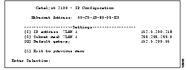

[I] IP Address. Select this option to assign Catalyst 2100 an IP address for SNMP management. The first time you assign an IP address, it takes effect immediately, and the internet protocol suite is activated and in-band management becomes available. If you subsequently change the IP address, you must reset Catalyst 2100 before the new IP address takes effect. If VLAN1 does not contain all ports as member ports, the following prompt is issued:
After selecting a VLAN, or if VLAN1 contains all ports as member ports, the next prompt is displayed. Type the IP address and press Return:
[S] Subnet mask. If IP subnetting is used, use this option to enter a subnet mask for the system or current VLAN. The new value takes effect after the next reset. If subnetting is not in use, the subnet mask is the same as the network mask. If VLAN1 does not contain all ports as member ports, you are prompted for the VLAN number and then the subnet mask. Type the IP address and press Return:
[G] Default gateway. Use this option to enter a default gateway address for SNMP management. Type the new gateway address at the prompt and press Return:
SNMP management, based on the Catalyst 2100 Management Information Base, or MIB, allows you to define management stations authorized to set configuration parameters and receive certain traps. If you have set up virtual LANs, each VLAN, acting as a discrete bridge, contains its own bridge MIB information.
Up to four management stations can be defined to set MIB objects and up to three stations can receive traps. If no management station is explicitly defined, any SNMP station can perform sets if the correct WRITE community string accompanies the request. Once a WRITE manager IP address is defined, however, only explicitly defined management stations can issue set operations on the switch.
You can use this menu to enable two traps and assign the management stations to receive them. Once a management station has been assigned, Catalyst 2100 generates several other traps documented in the section "Trap Clients and Traps" in the "In-Band Management" chapter. Any station can set Catalyst 2100 MIB objects if no station address has been explicitly defined.
All objects in the Catalyst 2100 MIB are documented in the Catalyst 2000 MIB Reference Manual. A functional list of the supported MIB objects can be found in "Standard MIBs and MIB Extensions" in the "In-Band Management" chapter.
Use this menu to define:
Display this menu by typing N on the Main Menu and S on the Network Management Menu.

[R] READ community string. Select this option to change the SNMP agent's Get community string. Catalyst 2100 will automatically attach a number to the string you enter to create a unique string for each of the four possible VLANs. For example, if you enter the string FINANCE, it becomes the READ community string for VLAN1, and FINANCE2, FINANCE3, and FINANCE4, become the READ community strings for VLAN2, VLAN3, and VLAN4, respectively. Enter a string of up to 32 characters and press Return.
[W] WRITE community string. Select this option to define a WRITE community string for Catalyst 2100. Catalyst 2100 will automatically attach a number to the string you enter to create a unique string for each of the four possible VLANs. The example for entering a READ community string applies equally here. Enter a string of up to 32 characters and press Return.
[1] 1st WRITE manager IP ADDRESS
[2] 2nd WRITE manager IP ADDRESS
[3] 3rd WRITE manager IP ADDRESS
[4] 4th WRITE manager IP ADDRESS
Select one of these options to define the IP address of a station authorized to issue WRITE statements to Catalyst 2100. To remove an entry, type 0.0.0.0. Type the IP address at the following prompt and press Return:
[F] First TRAP community string
[A] First manager IP address
[S] Second TRAP community string
[B] Second manager IP address
[T] Third TRAP community string
[C] Third TRAP manager IP address
A trap manager, also called a trap client, is a management workstation configured to receive and process traps. If a trap manager has not been defined, Catalyst 2100 does not send any traps. Use these options to define up to three trap managers and their accompanying community strings. See the section "Trap Clients and Traps" in the "In-Band Management" chapter for more information.
Type F and a trap manager community string of up to 32 characters and press Return.
Type A to define the IP address for the first trap manager. Type the IP address of the station and press Return at the next prompt:
Continue with further definitions as needed.
[U] Authentication trap generation. Select this option to enable or disable authentication traps that alert a management station of SNMP requests not accompanied by a valid community string. Even if this parameter is set, no trap can be generated if no trap manager addresses have been defined. Type E or D at the prompt and press Return.
[L] LinkUp/LinkDown trap generation. Catalyst 2100 generates the LinkDown trap whenever a port changes to a suspended or disabled state due to:
The LinkUp trap is generated whenever a port changes to enabled state due to:
Select this option to enable or disable the LinkUp/LinkDown trap. Type an E or D at the prompt and press Return.
Once you have defined a management workstation to receive traps, Catalyst 2100 will generate the traps in the following list by default. These traps are described in more detail in the section "Trap Clients and Traps" in the "In-Band Management" chapter.
Use this menu to display and configure the Spanning-Tree Protocol parameters defined for Catalyst 2100. The menu consists of an Information section that represents parameters controlled by Spanning-Tree Protocol operation as influenced by other bridges on the network, and a Settings section that defines Spanning-Tree Protocol parameters that are global to this bridge. There is also an Actions section that allows you to scroll through the virtual LANs that are each considered a separate bridge by Spanning-Tree Protocol. For more information, read the section "Spanning-Tree Protocol" in the "Concepts" chapter.
Display this menu by typing N on the Main Menu and B on the Network Management Menu. When you invoke this menu, the following prompt is displayed:
Type a VLAN to display the menu shown in Figure 5-9. If no VLANs have been configured, all ports belong to VLAN1.
The use of this menu requires an understanding of the following terms, some of which are displayed on the menu:

[S] Spanning-Tree Algorithm and Protocol. Select this option to enable or disable the Spanning-Tree Protocol, an industry standard way to ensure a loop-free configuration in the bridge topology. Redundant ports are kept in a standby (suspended) status and are automatically enabled when needed.
This parameter applies to all VLANs.
Type E or D at this prompt and press Return.
[B] Bridge priority. Select this option to force a bridge to be selected as the root bridge, or as a designated bridge. The bridge priority is a value used in determining the identity of the root bridge. The bridge with the lowest value has the highest priority and will be selected as the root. Type a value at the prompt and press Return:
[M] Max age when operating as root. Use this option to define the time in seconds to be used as the max age interval when this Catalyst 2100 becomes the root bridge. After this period expires, other bridges will notice that the root has not sent a configuration message and a new root will be selected. The default value is twenty seconds. Type the new number at the prompt and press Return:
[H] Hello time when operating as root. Select this option to define the hello time interval when this Catalyst 2100 becomes the root bridge. Valid values range from 1 to 10 seconds; the default is 2 seconds. Type the new value at the prompt and press Return: 
[F] Forward delay when operating as root. Select this option to define the time in seconds to be used as the forward delay interval when this Catalyst 2100 becomes the root bridge. Possible values are 4 to 30 seconds; the default value is 15 seconds.
Type a number at the prompt and press Return:
[A] Address aging time. Use this option to define the time-out, in seconds, after which an unused dynamic address is automatically removed. During a topology change, ports are aged more quickly by using the forward-delay parameter. When the topology stabilizes, this value again takes effect.
Possible values range from 10 to 1,000,000 seconds (about 11.5 days). The default is 300 seconds or 5 minutes. This value applies for all dynamic addresses in the Catalyst 2100 address table. Enter a value at the prompt and press Return:
[T] Strict state transition on suspended ports. When Catalyst 2100 suspends a port for jabber or address violation, the default is to return the port to its previous state without the normal forward delay. Enable this parameter to enforce the forward delay as defined by 802.1d.
[N], [P] Next VLAN bridge, Previous VLAN bridge. Use these options to scroll through the virtual LANs on the Catalyst 2100.
[G] Goto VLAN bridge. Use this option to enter the number of the VLAN whose parameters you want to display. Type a number at prompt and press Return.
Catalyst 2100 allows you to route a copy of incoming and outgoing traffic arriving on a port to a monitor port for analysis and troubleshooting. Use this menu to do the following:
Frame capturing cannot take place until all three of these parameters have been set.
Display this panel by typing M on the Main Menu.

[C] Capturing frames to the monitor. Select this option to enable-disable frame capturing. Type a letter at the prompt and press Return.
[M] Monitor port assignment. Use this option to define the port where captured frames are to be sent. Type a port number at the prompt and press Return.
[A] Add ports to capture list. Use this option to add ports to the capture list. Enter the numbers according to the example in the prompt and press Return.
[D] Delete ports from capture list. Use this option to delete port numbers from the capture list. Enter the numbers in the list you want to delete and press Return.
This menu displays the virtual LANs defined for this Catalyst 2100. You can use it to enable overlapping VLANs and display the VLAN Configuration Menu. See the section "Virtual LANs" in the "Concepts" chapter for more information and some sample configurations.
 Spanning-Tree may not prevent network loops in overlapping VLANs. Spanning-Tree may not prevent network loops in overlapping VLANs. |
Display this panel by typing V on the Main Menu.

[O] Overlapping of VLANs permitted. Select this option to allow membership of a port in more than one VLAN. Type a letter at the prompt and press Return.
[C] Configure VLAN. This option displays the VLAN Configuration Menu shown in Figure 5-12.
Use this menu to define up to four separate VLANs. As every port must belong to at least one VLAN, Catalyst 2100 is shipped with all ports belonging to VLAN1; all other VLANs are empty. For more details about the nature of Catalyst 2100 VLANs, see the section "Virtual LANs" in the "Concepts" chapter.
Display this menu by typing V on the Main Menu and then C on the VLAN Configuration Menu. Before the menu is displayed you are prompted for the VLAN number:
Type the number of the VLAN you want to display and press Return. Note that options [A] and [D] of this menu are displayed only if overlapping of ports is permitted.

[V] VLAN name. Select this option to enter a VLAN name of up to 60 characters. Type the name and press Return.
[M] Move member ports from other VLANs. Select this option to add ports to this VLAN and remove them from their previous configurations. Catalyst 2100 is shipped with all ports belonging to VLAN1. Type the numbers according to the conventions and press Return:
[A] Add member ports. Use this option to add a port to this VLAN. This feature does not remove the port from its previous VLAN membership. Use M, Move, to add a port and remove it from its previous VLAN. If overlapping membership is not enabled, you will be prompted to use the Move option. Type the numbers according to the conventions and press Return:
[D] Delete member ports. Use this option to delete member ports from this VLAN. Note that if a port belongs to only one VLAN, it should be moved rather than deleted. If you try to delete the port from its VLAN, Catalyst 2100 will abort the deletion and issue an error message.
Type the numbers according to the conventions and press Return:
[N] Next VLAN [P] Previous VLAN. Use these options to scroll through the available VLANs.
[G] Goto VLAN. Select this option to enter a VLAN to display. Type a number at the prompt and press Return:
By default, all multicast frames are forwarded to all ports in a VLAN. You can, however, register multicast frames so they are sent to only the ports you define. As these packets are then not forwarded to other ports, this reduces the amount of flooding performed by Catalyst 2100. It also opens up the possibility of using multicast packets for dedicated groupcast applications such as broadcast video. For more information on this feature, see the section "Flooding Controls" in the "Concepts" chapter.
Display this panel by typing R on the Main Menu. The first line of the menu, shown in Figure 5-13, displays the number of registered multicast addresses.

[R] Register a multicast address. Select this option to register a multicast address. You are prompted for both the address and the ports to which frames destined for this address are to be forwarded.
If you enter an invalid multicast address, the prompt will refresh itself so you can try again. Invalid addresses include non-multicast addresses, the broadcast address, and reserved multicast addresses such as those used for Spanning-Tree Protocol.
When you enter a valid address, the following prompt is displayed:

Type the port numbers and press Return. Typing errors will cause the prompt to be refreshed.
[L] List all registered multicast addresses. Use this option to list all multicast addresses that exist in Catalyst 2100. Addresses are listed with the port or ports to which they are assigned. Addresses with an asterisk are subject to source port filtering. See the section "Forwarding, Filtering, and Flooding" in the "Concepts" chapter for more information on source port filtering.
[U] Unregister a multicast address. Select this option to delete registered multicast addresses. You cannot delete those multicast addresses that are not considered registered. Type the address at the prompt and press Return.
[E] Erase all registered multicast addresses. Select this option to remove all registered multicast addresses. Press Y at the prompt.
Use this menu to display the status of a port, enter a port description, change the port's status, and define various Spanning-Tree Protocol parameters.
Display this menu by typing P on the Main Menu. The following prompt is displayed:
Type a port number to display and press Return. The menu shown in "Port Menu" in this chapter is displayed.

The following terms are used to describe the status of the port:
[D] Description/Name of port. Use this option to assign a name to the port. This could be Engineering Segment or any 60-character string. Type the port name at the prompt and press Return.
[S] Status of port. Use this option to enable a disabled port or disable a port in any operational state. Type E or D at the prompt and press Return.
The status indication shown on this panel will be one of the following:
[T] Type of connector. Select this option to define the connector type for port 25. Type S, R, or A at the prompt and press Return:
[F] Full duplex. Select this option to enable or disable full-duplex transmission on 100-Mbps ports. Full duplex is simultaneous transmission in both directions yielding an aggregate bandwidth of 200 Mbps. Because both ends must be configured for full duplex, the port cannot be connected to a repeater. A likely scenario would be to connect a full-duplex port to a server with a 100Base-TX adapter, configured for full duplex. You could also connect it to another Catalyst 2100 or other 100Base-TX switch or router, configured for full-duplex operation. Type an E or a D at the prompt and press Return.
[I] Port priority. Use this option to define which port is to remain enabled by Spanning-Tree Protocol if two ports form a loop. Type a number from 1 to 255 and press Return at the prompt.
[C] Path cost. Use this option to define the Spanning-Tree Protocol path cost of the port. It is inversely proportional to the LAN speed of the network interface at the port. A high path cost means the port has low bandwidth and should not be used if possible.The default is 1000/LAN-speed-in-Mbps. The path cost of 100-Mbps ports is thus 10, and 10-Mbps ports is 100. Enter a value at the prompt and press Return. This option also affects which port is to remain enabled by Spanning-Tree Protocol if two Catalyst 2100 connections form a loop.
[A] Port addressing. Select this option to display the Port Addressing Menu.
[V] View port statistics. Select this option to display the Detailed Port Statistics Menu.
[N] Next port [P] Previous port. Use these options to scroll back and forth between ports, displaying each port's characteristics.
[G] Goto port. Select this option to display the prompt. Type one of the values and press Return.
Use this menu to configure address security of a port and define static unicast and multicast addresses. Although multicast address registrations are configured elsewhere, you can use this menu to specify how a port filters and forwards unmatched unicast addresses and non-registered multicast addresses. For more information on these features, see the section "Flooding Controls" in the "Concepts" chapter.
Display this menu by typing A on the Main Menu and responding to the prompt with the port number.

The top of the panel displays the current addressing situation:
[T] Address Table Size. Select this option to define the size of the address table for a secured port. Type a number between 1 and 132 and press Return at the prompt.
[S] Addressing security. Use this option to secure a port. Alerts may be generated when secured ports attempt to learn new addresses and its address table is full. The port may be disabled or suspended due to such address violations. See the section "Securing Ports" in the "Concepts" chapter for more information. Type an E or D at the prompt and press Return.
[U] Flood unknown unicasts. When a frame with an unrecognized unicast destination address is received on any port, the default action is to forward the packet to all enabled ports. Use this option to inhibit the forwarding of unknown unicasts to this port. Type E or D at the prompt and press Return.
[M] Flood unregistered multicasts. When a frame with an unregistered multicast destination address is received on any port, the default action is to forward the packet to all enabled ports. Use this option to inhibit the forwarding of unregistered multicast addresses to this port. Type E or D at the prompt and press Return.
[A] Add a static address. Use this option to add a static unicast address to the port's address table. If the address table is already full, an error message is generated. If there is room in the table, type E or D at the prompt and press Return.
[D] Define a restricted static address. Packets with static addresses are usually accepted from any source port. A restricted static address, which corresponds to source port filtering in 802.1d, is accompanied by a list of ports that are allowed to send frames to this address and port. Type a unicast or multicast address and press Return.
You are then prompted for the port numbers allowed to send to this address. Type the port numbers at the prompt and press Return. Catalyst 2100 checks the list of ports for typing errors and, if there are any, redisplays the prompt.
[L] List addresses. Select this option to list all dynamic and static addresses that belong to this port. Catalyst 2100 displays up to 15 addresses per screen; static addresses are listed first.
[E] Erase an address. Use this option to erase a dynamic or static address assigned to the current port. Type the address at the prompt and press Return.
[R] Remove all addresses. Select this option to remove all dynamic and static addresses currently associated with the port. Type Y or N at the confirmation prompt and press Return.
[C] Configure port. Select this option to display the Port Menu.
[V] View port statistics. Select this option to display the Detailed Port Statistics Menu.
[N] Next port [P] Previous port. Use these options to scroll back and forth between ports, displaying each port's characteristics.
[G] Goto port. Select this option to display the prompt:
Type one of the values and press Return to display the port.
This display-only menu shows frame transmit and receive statistics captured by
Catalyst 2100. Statistics are displayed on a per-port basis. Press the Spacebar to update the statistics.
Display the menu by typing V on the Port Menu or on the Port Addressing Menu.

Performance or connectivity problems could be evident in the port statistics, particularly those under the heading Errors. For example, FCS and alignment errors could be the result of cabling problems such as the following:
For more information on responding to the errors found here, see the "Troubleshooting" chapter. The following definitions of the types of errors found on this panel are taken from RFC 1398:
[A] Port addressing. Display the Port Addressing Menu.
[C] Port configuration. Display the Port Menu.
[N] Next port [P] Previous port. Use these options to scroll back and forth between ports, displaying each port's characteristics.
[G] Goto port. Type a port number and press Return to display the port's statistics.
[R] Reset port statistics. Select this option if you want to clear this port's statistics, including those found here and in the Utilization Statistics and Exceptions Reports. Type Y at the following prompt and press Return:
It may be required to upgrade Catalyst 2100's firmware in order to incorporate future corrections or enhancements. Upgrading Catalyst 2100 firmware is performed by downloading an upgrade file directly into FLASH memory. When new firmware is downloaded, Catalyst 2100 resets, and the new firmware begins executing immediately. To avoid writing over itself, Catalyst 2100 must be executing out of EPROM for the firmware to be upgraded.
Use this menu to display the firmware version currently in use by Catalyst 2100 and to perform firmware upgrades. You can also download diagnostic software for use by customer support.
Display this menu by typing F on the Main Menu.

How you upgrade the firmware depends on your installation. There are three possibilities:
in-progress.
Under the heading System Information you can see the past and current state of the
Catalyst 2100 firmware. The EPROM heading reflects the factory-installed firmware; the FLASH heading shows the version number of the most recent upgrade and when it was installed; the station address displays the station used for the upgrade. If a terminal was used, it will say serial terminal. Also displayed is the status of the most recent upgrade: valid, in-progress, or invalid.
[C] Current system firmware source. The source of the currently executing Catalyst 2100 firmware, EPROM or FLASH, is displayed at the top of the menu. Catalyst 2100 must be executing out of EPROM for the firmware to be upgraded. Type E or F at the prompt and then press Return to change the source. If you press Return without typing a letter, or after clearing an entry with Backspace, the setting is not changed and the previous menu is displayed.
[S] Server: IP address or TFTP server. Type the IP address of the TFTP server where a Catalyst 2100 upgrade file is located.
[F] Filename for firmware upgrades. Type the name of the firmware upgrade file to be downloaded and press Return. The file should be on a TFTP server.
[A] Accept upgrade transfer from other hosts. You have the option of accepting, or not, upgrades from TFTP clients on the network. Use this option to enable or disable this function and press Return.
[U] System XMODEM upgrade. Select this option to upgrade the firmware using a modem. If the firmware is currently running from EPROM, you will be prompted to confirm the upgrade. Type Y to begin the transfer or N to return to the Firmware Upgrade Menu. The next prompt is:
C is the first XMODEM/CR protocol request. Use the appropriate application-specific command to start the transfer. Upon successful completion of the transfer, Catalyst 2100 resets and the newly downloaded firmware begins to execute. The Logon Security Menu is displayed.
[T] System TFTP upgrade. Use this option to upgrade the firmware from a TFTP server. The address of the server and the name of the file must already be set. Depending on whether a valid firmware has been written to flash memory, the following message is displayed:
[D] Download test subsystem (XMODEM). This option is reserved for use by the Cisco Systems customer support group and is used to download diagnostic software.
Use this menu to define the RS-232 port's physical characteristics--baud rate, stop bits and the like--and call-features such as the time delay between outgoing calls. Note that the changes that you make are not invoked until you press G to activate them. Press C to cancel the session and return to the previous settings.
Display this panel by typing I on the Main Menu.

[B] Baud rate. Type the baud rate for the Catalyst 2100 RS-232 serial port and press Return.
[D] Data bits. Type the data bits value for the serial port and press Return. Valid values are 7 and 8.
[S] Stop bits. Type the stop-bits value for the serial port and press Return.
[P] Parity settings. Change the parity settings for the serial port and press Return.
[M] Match remote baud rate. Select this feature to enable the RS-232 port to automatically match the baud rate of an incoming call. Catalyst 2100 only matches a baud rate lower than its configured baud rate. After the call, Catalyst 2100 reverts back to its configured rate.
[A] Auto answer. Select this feature to enable the auto-answer feature. Type E or D at the prompt and press Return.
[N] Number for dial-out connection. Enter the phone number Catalyst 2100 is configured to use when dialing out. This number is dialed when Catalyst 2100 is configured to communicate with a remote terminal upon power-up or reset. If the dial-out is unsuccessful and auto-answer is enabled, Catalyst 2100 will cease dialing and await incoming calls.
Up to 48 characters can be entered. Use the Backspace followed by Return to delete the number. Using the format required by your modem, type the number at the prompt and press Return.
[T] Time delay between attempts. Type the amount of time in seconds between dial-out attempts and press Return. 0 disables retry.
[I] Initialization string for modem. Change the initialization string to match your modem requirements. Up to 48 characters can be entered. A single Backspace followed by Return deletes the current string and restores the default string E0V1M1 for Hayes-compatible modems.
Type the new string at the prompt and press Return.
[C] Cancel and restore previous group settings. Select this option to undo any new values entered for the baud rate, data bits, stop bits and parity setting. Values are restored to those last saved.
[G] Activate group settings. This option activates the setting you have entered for baud rate, data bits, stops bits, and parity settings. After selecting this option, configure the attached terminal to match the new settings. Enter Y or N at the prompt.
Use this menu to display network statistics in the form of summary displays showing all ports. Press U on the Main Menu to display this menu. These statistics are read only; press the space bar to refresh them at any time.

This panel summarizes the status of all ports as defined on the Ports Menu. Definitions of these terms are in the section "Port Configuration" in this chapter.
Display this panel by typing U on the Main Menu and P on the Usage Summary Menu.

This panel displays the port's address mode, dynamic or static, and how many addresses have been assigned to the port.
Display this panel by typing U on the Main Menu and A on the Usage Summary Menu.

The two columns on this panel can have the following values:
The Exceptions Report Menu displays the number of receive errors, transmit errors, and security violations for each port.
Display this panel by typing U on the Main Menu and E on the Usage Summary Menu.

The figures displayed are actually totals of various kinds of errors:
This panel displays the frame-count statistics generated by Catalyst 2100.
Display this panel by typing U on the Main Menu and U on the Usage Summary Menu.

Column headings have the following meanings:
[R] Reset all statistics. Select this option to reset all statistics to 0. Type a letter at the confirmation prompt and press Return.
Use this menu to display the peak bandwidth of the network during a given period of time. Catalyst 2100 displays a list of the last 12 recordings of maximum bandwidth, in Mbps, according to a time interval you set. You can reset or clear the statistics at any time.
Display this panel by typing U on the Main Menu and B on the Usage Summary Menu.

[T] Capture time interval. Use this option to define the time interval during which data is collected to calculate bandwidth usage.
[C] Clear table. Select this option to clear the bandwidth table. Respond to the confirmation prompt and press Return.
[R] Reset current entry. This option sets the current table entry to 0 and allows new information to be recorded. The current table entry is marked by an asterisk (*). Respond to the confirmation prompt and press Return.
|
|