|
|

This chapter describes how to unpack, install, cable, and run the power-on self-test (POST) on the GigaStack GBIC. After power on, you can manage GBIC ports as you would manage fixed ports on the switch, through the web-based Cluster Management Suite (CMS), or through the console port or a Telnet connection to access the IOS command-line interface.
Before you install a GigaStack GBIC, ensure that these items are included in the package:
If anything is missing, contact your Cisco Systems customer service representative.
 |
Note You can order a 1-m cable separately. |
This section lists international regulatory information for the GigaStack GBIC.
U.S. regulatory information for this product is in the front matter of this manual.
This is a Class A Information product. When used in a residential environment, it may cause radio frequency interference. Under such circumstances, the user may be requested to take appropriate countermeasures.

This is a Class A product based on the standard of the Voluntary Control Council for Interference by Information Technology Equipment (VCCI). If this equipment is used in a domestic environment, radio disturbance may arise. When such trouble occurs, the user may be required to take corrective actions.

| |||
|
| ||
This equipment is a Class A product and should be used and installed properly according to the Hungarian EMC Class A requirements (MSZEN55022). Class A equipment is designed for typical commercial establishments for which special conditions of installation and protection distance are used.
Figyelmeztetés a felhasználói kézikönyv számára:
Ez a berendezés "A" osztályú termék, felhasználására és üzembe helyezésére a magyar EMC "A" osztályú követelményeknek (MSZ EN 55022) megfeleloen kerülhet sor, illetve ezen "A" osztályú berendezések csak megfelelo kereskedelmi forrásból származhatnak, amelyek biztosítják a megfelelo speciális üzembe helyezési körülményeket és biztonságos üzemelési távolságok alkalmazását.
Before you install the GigaStack GBIC, ground yourself by touching the metal part of the chassis to avoid electrostatic discharge (ESD). You should also keep the GigaStack GBIC in its antistatic shielded bag until you are ready for installation.
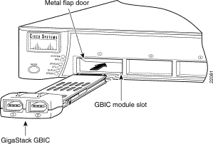
Gigabit Ethernet switches are shipped without the GigaStack GBIC. However, you can install the GBIC into GigaStack GBIC slots, as shown in Figure 2-1.
Install a GigaStack GBIC as follows:
Step 2 If you want to use the GigaStack cable connector (hereafter referred to as the clip), see the "Attaching the GBIC Clip" section.
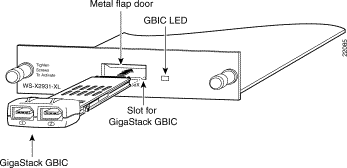
Step 3 Grip the sides of the GBIC with your thumb and forefinger, and insert it into the GBIC slot on a switch front panel, as shown in Figure 2-1, or the Catalyst 2900 XL 1000BASE-X module slot, as shown in Figure 2-2.
The GigaStack GBIC is keyed to prevent incorrect insertion.
Step 4 Slide the GigaStack GBIC through the flap covering the opening into the slot until you hear a click. The click means the GigaStack GBIC is locked into the slot.
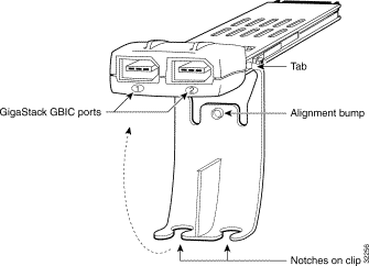
Each GigaStack GBIC ships with a removable clip that can be attached to provide extra security against accidental cable removal. If you use the clip, you must attach it before inserting the GBIC into the slot.
Attach the clip as follows:
Step 2 Insert the cable connector into the GBIC port according to your configuration.
Step 3 Swing the GBIC clip up toward the GBIC so that the alignment bump in the clip seats in the indentation on the GBIC bottom.
Step 4 Secure the cable in a clip notch as shown in Figure 2-4.

Step 5 Insert the GBIC into the slot. Follow the steps in the "Installing a GigaStack GBIC" section.
All ports are set to autonegotiate the duplex mode for your GigaStack GBIC. You must keep this default setting; autonegotiation must not be disabled.
For information about the supporting switches and software, see the "Switches Supporting the GBIC" section and the "Minimum IOS Release for Redundant Loop Configurations" section.
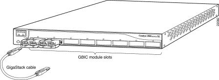
Insert the GigaStack cable connector into the GigaStack GBIC port, as shown in Figure 2-5.
 |
Note The GBIC module slot LED is amber while the Spanning Tree Protocol discovers the topology and searches for loops. This takes about 30 seconds. The port status LED then turns green. |
 |
Note Always use a GigaStack cable to connect a GigaStack GBIC to any device. For more information, see the "GigaStack GBIC Cabling" section. |
You can create these configurations:
In a point-to-point configuration or cascaded stack configuration, the GigaStack GBIC can use the ports listed in Table 2-1 to connect to other devices.
| Device | Available GigaStack GBIC Ports |
1000BASE-X module (for modular 2900 XL switches) | 2 |
3500 XL switches | 2 |
2950 switches | 2 |
3550 multilayer switches | 2 |
For more information, see the "Point-to-Point Connections" section, the "Cascaded Stack Connections" section, and the "Cascaded Stack Connections with a Redundant Link" section.
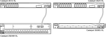
A point-to-point connection operates in full-duplex mode. Figure 2-6 shows an example of supporting switches with point-to-point connections.
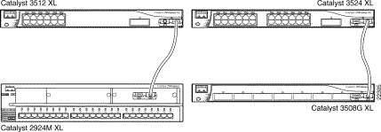
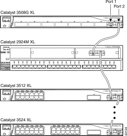
You can connect from three to nine switches in a cascaded stack configuration. The cascaded stack operates in half-duplex mode. Figure 2-7 shows the connections on some supporting switches.
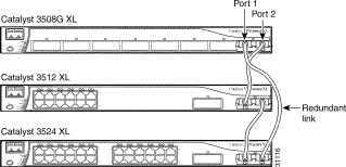
You can form a redundant link by connecting the open ports on the top and bottom GigaStack GBICs within the same stack, as shown in Figure 2-8.
GigaStack GBICs installed in a stack support a loop configuration only if every Catalyst 2900 XL and 3500 XL switch in the stack is running IOS software Release 12.0(5)XU or later, Release 12.1(6)EA2 or later for Catalyst 2950 switches, and Release 12.1(4)EA1 or later for Catalyst 3550 switches.
For Catalyst 2900 XL and 3500 XL switches running IOS software earlier than Release 12.0(5)XU, an illegal loop is created under these conditions:
If a Catalyst switch is connected through its GigaStack GBIC to another switch's GigaStack GBIC that does not support loop detection, the GBIC LEDs turn these colors:
To avoid problems with loop configurations, make sure that all switches in your stack are running the appropriate IOS release as shown in Table 1-5. For more information, see the "Minimum IOS Release for Redundant Loop Configurations" section. For switch software upgrade information, refer to the release notes for your switch.
Remove a GigaStack GBIC as follows:
Step 2 To remove, slide the GigaStack GBIC out of the slot. A flap drops down to protect the internal connector.
Step 3 If you are using the GBIC clip to secure the GBIC cables, remove the clip from the GigaStack GBIC by pulling the tabs from the slots on the GBIC. Remove the cables from the notches in the clip.
Step 4 Disconnect the cable from the GigaStack GBIC port.
 |
Warning Ultimate disposal of this product should be handled according to all national laws and regulations. |
All supporting switches perform a power-on self-test (POST) on the GigaStack GBIC. When you insert the GigaStack GBIC into the switch or module slot, the port LED on the switch or module turns amber while STP checks for possible loops and then turns green. When you insert a GigaStack GBIC cable into the GBIC port, the GigaStack GBIC port turns green if there is network connectivity; no additional configuration is needed. For more information about the LED meanings, see the "GigaStack GBIC LEDs" section and the "GBIC Module Slot LEDs" section.
![]()
![]()
![]()
![]()
![]()
![]()
![]()
![]()
Posted: Fri Mar 29 13:24:50 PST 2002
All contents are Copyright © 1992--2002 Cisco Systems, Inc. All rights reserved.
Important Notices and Privacy Statement.