|
|

This document provides information about installing and maintaining the Cisco 6100/6130 system fan tray. The fan tray is installed in the following chassis:
The fan tray is installed directly beneath the DSLAM and provides forced air cooling for the Cisco 6100/6130 systems.
 |
Note The -48VA and -48VB power connections on the fan tray backplane have been relabeled to be consistent with the Cisco 6100/6130 chassis. You may see both versions of the fan tray backplane in the field. |
This document includes the following sections:
The system requires forced air cooling when you use one of the following system components:
You must install a fan tray with three fan modules below the chassis and leave 1 rack unit (RU) of space below the fan tray for the intake plenum. Figure 1 shows the front view of the fan tray.

 |
Note The fan tray must be bolted into the rack and connected to the chassis. If you are using multiple chassis in your configuration, a fan tray must be installed under each chassis. |
There is an LED on the front of each of the three fan modules. If the LED is
Figure 2 shows the backplane of the fan tray.

Table 1 describes the connectors on the backplane of the fan tray.
| Identifier | Name | Description |
|---|---|---|
P1 | Power | Terminal block connector with four dual power input connections (-48VA, -48VB, and two -48VB RTN). |
P21 | Alarm | A two-position header providing connections for fan tray alarm contacts. |
J12 | Alarm | 26-pin Small Computer System Interface (SCSI) connector used to connect the fan tray to the Cisco 6130 chassis. |
| 1This connector is used in a Cisco 6100/6130 with NI-1 systems or a Cisco 6100 with NI-2 system. 2This connector is used in a Cisco 6130 with NI-2 system. |
The following tools and equipment are required for fan tray installation or removal. Only the four mounting screws are provided by Cisco.
Two people are needed for lifting and installing the fan tray.
 |
Caution Proper ESD protection is required whenever you handle Cisco digital subscriber line (DSL) access multiplexer (DSLAM) equipment. Installation and maintenance personnel should be properly grounded using ground straps to eliminate the risk of ESD damage to the equipment. Modules are subject to ESD damage whenever they are removed from the chassis. |
 |
Caution If fuses are already installed in the fuse and alarm panel, remove them. You can replace the fuses after the fan tray is installed. Do not power on the system while you install and connect the fan tray. |
 |
Caution It is important that the Cisco 6100/6130 cooling fans run continuously. The system could suffer thermal damage if the fans stop running for more than 30 minutes. |
 |
Warning The power supply circuitry for the fan tray may constitute an energy hazard. Remove all jewelry (including rings, necklaces, and watches) before installing or replacing the fans. Metal objects can come into contact with exposed power supply wiring or circuitry inside the fan tray. This could cause the metal objects to heat up and cause serious burns or weld the metal object to the equipment. |
 |
Warning Do not reach into a vacant slot or chassis while you install or remove a fan. Exposed circuitry could constitute an energy hazard. |
 |
Warning Installation and maintenance should be performed only by trained service personnel who are aware of the potential hazards involved (for example, fire and electric shock). |
 |
Warning To prevent a Cisco 6100 Series system from overheating, do not operate it in an area that exceeds the maximum recommended ambient temperature of 104°F (40°C) in a CO location. |
 |
Warning Two people are required to lift the fan tray chassis. Grasp the fan tray chassis underneath the lower edge and lift with both hands. To prevent injury, keep your back straight and lift with your legs, not your back. |
 |
Warning To prevent bodily injury when mounting or servicing this unit in a rack, you must take special precautions to ensure that the system remains stable. The following guidelines are provided to ensure your safety: |
See the following sections to install and connect the fan tray.
 |
Note You must complete all the tasks in one section before moving to the next section. |
Complete the following steps to install the fan tray in the rack:
 |
Note If you are using more than one chassis in your configuration, you must install a fan tray under each chassis. |
a. Inspect the packing container. If any damage or other signs of mishandling are evident, inform both the local freight carrier and Cisco before unpacking. Your freight carrier can provide you with the procedures necessary to file a claim for damages.
b. Carefully open the packing container and remove the fan tray.
c. Open the accessory kit that contains the documentation and the four mounting screws. Do not use a knife to open this box.
d. Carefully examine the fan tray chassis and fans for any damage. If you suspect any damage from shipping, contact your local freight carrier for procedures on damage claims.
Step 2 Remove the fuses from the fuse and alarm panel. By removing the fuses from the fuse and alarm panel, the system will not be powered while you install and connect the fan tray.
Step 3 Place the fan tray chassis on a flat and stable surface (for example, a table top).
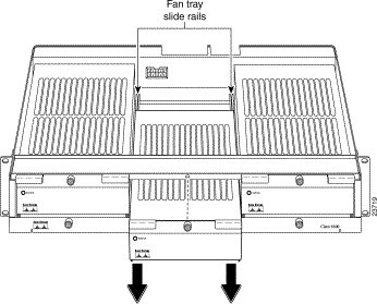
Step 4 Locate the first fan module and unscrew the thumbscrew that holds the fan module in place (the screw at the top of each fan module), as shown in Figure 3.

Step 5 Carefully remove the fan module by pulling it toward you. The fan module is located on slide rails for easy removal and installation. (See Figure 4.)
Step 6 Place the fan module on a flat and stable surface (for example, a table top) until you are ready to reinsert it into the fan tray.
Step 7 Repeat Steps 4 through 6 for each fan module.
See the following steps for installing a fan tray for a Direct Connect with a plain old telephone service (POTS) splitter configuration.
Allow an additional 1 RU of space between the fan tray and the POTS splitter. This space allows for the intake plenum.
Step 2 Use four mounting screws and a Phillips-head screwdriver to bolt the fan tray in the rack above the POTS splitter.
Step 3 Align a fan module with the fan tray slide rails inside the fan tray.
Step 4 Slide the fan module into the fan tray.
Step 5 Tighten the thumbscrew above the fan module.
Step 6 Repeat Steps 4 through 6 for each fan module.
 |
Note For information about fan module and air filter replacement, see the "Fan Tray Maintenance" section. |
See the following steps for installing a fan tray for a Direct Connect without a POTS splitter configuration.
Allow 1 RU of space under the fan tray. This space allows for the intake plenum.
Step 2 Use four mounting screws and a Phillips-head screwdriver to bolt the fan tray in the rack.
Step 3 Align a fan module with the fan tray slide rails inside the fan tray.
Step 4 Slide the fan module into the fan tray.
Step 5 Tighten the thumbscrew above the fan module.
Step 6 Repeat Steps 4 through 6 for each fan module.
 |
Note For information about fan module and air filter replacement, see the "Fan Tray Maintenance" section. |
During the system installation, complete the following steps to connect the grounding lug on the fan tray directly to the rack.
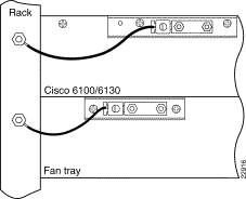
Step 2 Measure enough wire to connect the fan tray to the rack. Use 14 AWG or thicker green or green with yellow stripes stranded copper wire for the fan tray. (See Figure 5 for grounding wire location.)
Figure 5 shows how to ground the fan tray to the rack.
 |
Tip Make sure your wire is as short as possible to make the connection. |
Step 3 Use a wire stripper to remove the casing from both ends of the wires.
Step 4 Use a 3/16-inch flat-head screwdriver to loosen the screw on the rack.
Step 5 Hook one end of the copper wire around the screw on the rack.
Step 6 Tighten the rack screw over the copper wire.
Step 7 Use the flat-head screwdriver to loosen the compression screw that is provided on the grounding lug of the fan tray.
The grounding lug is located in the upper left corner of each fan tray (viewed from the rear).
Step 8 Insert the other end of the copper wire under the compression screw.
Step 9 Tighten the compression screw over the copper wire.
 |
Note Do not ground the components in a rack by chaining them together. |
External power is supplied to the system as -48 VDC from the Central Office (CO) power source or rectifier to the fuse and alarm panel. Power is fed from the fuse and alarm panel to the fan tray by a terminal block connector with four dual power connections (P1) that are located at the top of the fan tray backplane. Figure 6 shows the location of the power connection (P1) on the fan tray.
 |
Note The fuse and alarm panel and wires are not provided by Cisco. |

 |
Note Connect each system component to a separate fuse. Do not power the components in the
rack by chaining them together. See the appropriate hardware installation guide for the calculation tables that are necessary to determine the minimum fuse rating for each component that is wired to the fuse and alarm panel. Refer to the label on the back of the fan tray to determine the maximum fuse rating. |
Step 2 Measure enough wire (14 to 18 AWG copper solid or stranded wire) to connect each of the fan tray power connections to the fuse and alarm panel.
Figure 7 shows the power connections from the fan tray to the fuse and alarm panel for a dual-power feed.

Step 3 Use a wire stripper to remove the casing from both ends of the wires.
Step 4 Use a Phillips-head screwdriver to attach a wire to the -48VA power input connection on the fan tray (P1).
Step 5 Attach the wire to the fuse and alarm panel NEG DC connector. See Figure 7 for correct placement.
Step 6 Use a Phillips-head screwdriver to attach a wire to the -48VB power input connection on the fan tray (P1).
Step 7 Attach the wire to the fuse and alarm panel NEG DC connector. See Figure 7 for correct placement.
Step 8 Use a Phillips-head screwdriver to attach a wire to an RTN power return connection on the fan tray (P1).
Step 9 Attach the wire to a fuse and alarm panel POS RTN connector.
Step 10 Repeat Steps 8 and 9 for the remaining RTN power return connection.
Step 11 Use a socket driver or a Phillips-head screwdriver to attach the clear cover over the fan tray power connections.
 |
Note Each fan tray requires a 1.25A fuse. |
Complete the following steps to attach the fan tray power connections to the fuse and alarm panel for a single-power feed:
Step 2 Measure enough wire (14 to 18 AWG copper solid or stranded wire) to connect each of the fan tray power connections to the fuse and alarm panel.
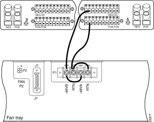
Figure 8 shows the power connections from the fan tray to the fuse and alarm panel for a single-power feed.
Step 3 Use a wire stripper to remove the casing from both ends of the wires.
Step 4 Use a Phillips-head screwdriver to attach a wire to the -48VA power input connection on the fan tray (P1).
Step 5 Attach the wire to the fuse and alarm panel NEG DC connector.
Step 6 Use a Phillips-head screwdriver to attach a wire to an RTN power return connection on the fan tray (P1). See Figure 8 for correct placement.
Step 7 Attach the wire to the fuse and alarm panel POS RTN connector. See Figure 8 for correct placement.
Step 8 Use a Phillips-head screwdriver to attach a wire to connect the -48VA and -48VB power input connections to each other.
Step 9 Use a Phillips-head screwdriver to attach a wire to connect the RTN power return connections to each other.
Step 10 Use a socket driver or a Phillips-head screwdriver to attach the clear cover over the fan tray power connections.
 |
Note Each fan tray requires a 1.25A fuse. |
See the following sections to connect the fan tray to a particular chassis.
To connect the fan tray to the Cisco 6100/6130 with NI-1 system, you must connect the fan tray alarm contacts to the chassis so that the fan tray alarms can be transmitted to the management software.
Complete the following steps to connect the fan tray alarm contacts:
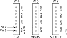
Figure 9 shows how the fan tray two-position header (P2) connects to the fan tray alarm contacts
(P14, pins 7 and 8) on the Cisco 6100/6130 with NI-1 backplane.
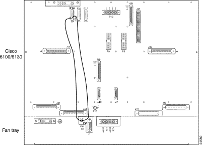
See Figure 10 for a close view of the alarm contact pinouts.
Step 2 Use a wire stripper to remove the casing from both ends of the wires.
Step 3 Wire P2 on the backplane of the fan tray to P14 (pin 7) on the backplane of the Cisco 6100/6130 with NI-1 to connect the Fan Alarm+ contact. Use a wire-wrapping tool to attach the wire to the contacts.
Step 4 Wire P2 on the backplane of the fan tray to P14 (pin 8) on the backplane of the Cisco 6100/ 6130 with NI-1 to connect the Fan Alarm- contact. Use a wire-wrapping tool to attach the wire to the contacts.
Step 5 Reinsert the fuses in the fuse and alarm panel. When you reinsert the fuses, the system powers on.
Step 6 Verify that the fans are operational by locating the LED on the front of each fan. If the LED is green, the fan is operational. If the LED is not green, the fan is not operational and the fan tray is in alarm mode. Refer to the Cisco 6100 Series with NI-1 Alarm Summary Guide for corrective action.
To connect the fan tray to the Cisco 6100 with NI-2 system, you must connect the fan tray alarm contacts to the chassis so that the fan tray alarms can be transmitted to the management software.
Complete the following steps to connect the fan tray alarm cable:
Step 2 Attach the P2 connector of the same fan tray alarm cable to connector P4 on the system I/O card, as shown in Figure 11.

Step 3 Reinsert the fuses in the fuse and alarm panel. When you reinsert the fuses, the system powers on.
Step 4 Verify that the fans are operational by locating the LED on the front of each fan. If the LED is green, the fan is operational. If the LED is not green, the fan is not operational and the fan tray is in alarm mode. Refer to the Cisco 6100 with NI-2 Hardware Installation Guide for corrective action.
To connect the fan tray to the Cisco 6130 with NI-2 system, you must connect the fan tray alarm contacts to the chassis so that the fan tray alarms can be transmitted to the management software.
Complete the following steps to connect the fan tray alarm cable:
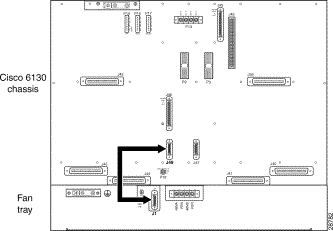
Step 2 Attach the other end of the same fan tray alarm cable to connector J49 on the Cisco 6130 with NI-2 backplane, as shown in Figure 12.
Step 3 Reinsert the fuses in the fuse and alarm panel. When you reinsert the fuses, the system powers on.
Step 4 Verify that the fans are operational by locating the LED on the front of each fan. If the LED is green, the fan is operational. If the LED is not green, the fan is not operational and the fan tray is in alarm mode. Refer to the Cisco 6130 with NI-2 Hardware Installation Guide for corrective action.
Complete the following sections to remove the fan tray.
 |
Note It is important that you complete each step before moving on to the next step. |
Depending on your chassis, choose from one of the following sections to disconnect the fan tray.
Complete the following steps to disconnect the fan tray from the Cisco 6100/6130 with NI-1 system.
Step 2 On the Cisco 6100/6130 with NI-1 and fan tray backplanes, locate the 24 to 28 AWG solid wire that you used to connect the fan tray alarm contacts.
Figure 13 shows the Cisco 6100/6130 with NI-1, fan tray backplanes, and fan tray alarm contacts.

Step 3 Disconnect the P2 on the backplane of the fan tray from the P14 (pin 7) on the backplane of the Cisco 6100/6130 with NI-1.
Step 4 Disconnect the P2 on the backplane of the fan tray from the P14 (pin 8) on the backplane of the Cisco 6100/ 6130 with NI-1.
Complete the following steps to disconnect the fan tray from the Cisco 6100 with NI-2 system.
Step 2 Disconnect the P1 connector of the fan tray alarm cable (part number 72-2086-01) from the P2 connector on the fan tray backplane, as shown in Figure 14.
Step 3 Disconnect the P2 connector of the same fan tray alarm cable from the P4 connector on the system I/O card, as shown in Figure 14.

Complete the following steps to disconnect the fan tray from the Cisco 6130 with NI-2 system.
Step 2 Disconnect the fan tray alarm cable (part number 72-1912-01) from connector J1 on the fan tray backplane, as shown in Figure 15.
Step 3 Disconnect the other end of the same fan tray alarm cable from connector J49 on the Cisco 6130 with NI-2 backplane, as shown in Figure 15.

Depending on your power feed, choose from the following sections to disconnect the fan tray power connections.
Step 2 Locate the wire (14 to 18 AWG copper solid or stranded wire) used to connect each of the fan tray power connections to the fuse and alarm panel.
Figure 16 shows the power connections from the fan tray to the fuse and alarm panel for a dual-power feed.

Step 3 Use a Phillips-head screwdriver to detach the wire from the -48VA power input connection on the fan tray (P1).
Step 4 Detach the wire from the fuse and alarm panel NEG DC connector. See Figure 16 for the location of the connector.
Step 5 Use a Phillips-head screwdriver to detach the wire from the -48VB power input connection on the fan tray (P1).
Step 6 Detach the wire from the fuse and alarm panel NEG DC connector. See Figure 16 for the location of the connector.
Step 7 Use a Phillips-head screwdriver to detach a wire from an RTN power return connection on the fan tray (P1).
Step 8 Detach the wire from a fuse and alarm panel POS RTN connector.
Step 9 Repeat Steps 7 and 8 for the remaining RTN power return connection.
Step 2 Locate the wire (14 to 18 AWG copper solid or stranded wire) used to connect each of the fan tray power connections to the fuse and alarm panel.
Figure 17 shows the power connections from the fan tray to the fuse and alarm panel for a single-power feed.

Step 3 Use a Phillips-head screwdriver to detach a wire from the -48VA power input connection on the fan tray (P1).
Step 4 Detach the wire to the fuse and alarm panel NEG DC connector.
Step 5 Use a Phillips-head screwdriver to detach a wire to an RTN power return connection on the fan tray (P1). See Figure 17 for connector location.
Step 6 Detach the wire from the fuse and alarm panel POS RTN connector. See Figure 17 for connector location.
Step 7 Use a Phillips-head screwdriver to detach the wire connecting the -48VA and -48VB power input connections to each other.
Step 8 Use a Phillips-head screwdriver to detach the wire connecting the RTN power return connections to each other.
Complete the following steps to disconnect the grounding lug on the fan tray directly from the rack.
Figure 18 shows the grounding wire location.

Step 2 Use a 3/16-inch flat-head screwdriver to loosen the screw on the rack.
Step 3 Unhook one end of the copper wire around the screw on the rack.
Step 4 Refasten the rack screw.
Step 5 Use the flat-head screwdriver to loosen the compression screw that is provided on the grounding lug of the fan tray.
The grounding lug is located in the upper left corner of each fan tray (viewed from the rear).
Step 6 Unhook the other end of the copper wire under the compression screw.
Step 7 Refasten the compression screw.
Step 8 Discard the cooper wire.
Complete the following steps to remove the fan tray from the rack:

Step 2 Carefully remove the fan module by pulling it toward you. The fan module is located on slide rails for easy removal and installation. (See Figure 20.)

Step 3 Place the fan module on a flat and stable surface (for example, a table top) until you are ready to reinsert it into the fan tray.
Step 4 Repeat Steps 2 through 4 for each fan module.
Step 5 Use a Phillips-head screwdriver to unbolt the fan tray from the rack.
 |
Warning Two qualified personnel should hold the fan tray while unbolting it from the rack. |
Step 6 Remove the fan tray from the rack.
The following sections describe the preventive maintenance procedures for the fan tray:
The air filter is located directly below the three fans in the fan tray. When this filter becomes dirty, replace it. Replace the air filter every 60 days. If you notice a significant accumulation of dust in the filter prior to 60 days, replace the filter at that time. Record the date each time you replace the filter.
You can order a replacement air filter (part number 6100-AF-01=) through Cisco.
To replace the air filter, use these steps:
Step 2 Locate and unscrew the three thumbscrews that are located across the bottom of the fan tray. (See Figure 21.)

Step 3 Carefully remove the air filter door.
Step 4 Slide the air filter out from the bottom of the fan tray. Gently pull the used air filter toward you to remove it from the fan tray (see Figure 22). The fan tray remains operational while you replace the air filter.

Step 5 Hold the replacement air filter so that the air flow arrows on the end of the air filter face upward. (See Figure 23.)
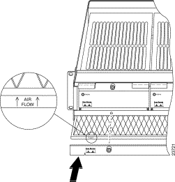
Step 6 Slide the filter into its slot at the bottom of the fan tray. (See Figure 23.)
Step 7 Place the air filter door back on the fan tray and tighten the three thumbscrews. (See Figure 23.)
Step 8 Discard the used air filter.
If a fan module is running too slowly or is no longer operational, the management software generates an alarm. You will need to replace the nonoperational fan. While you are replacing the nonoperational fan, the operational fans continue to run. You can order a replacement fan (part number 6100-FU-01=) through Cisco.
 |
Warning If you do not have a replacement fan module available, pull all of the line cards away from the backplane connection and power off the system until a replacement fan module is available. |
To replace a fan module in the fan tray, complete these steps:
Step 2 Locate the fan module and unscrew the thumbscrew that holds the fan module in place (the screw at the top of the fan module). (See Figure 24.)

Step 3 Carefully remove the fan module by pulling it toward you. The fan module is located on slide rails for easy removal and installation. (See Figure 25.)

 |
Caution It is important that the Cisco 6100/6130 system cooling fans run continuously. |
Step 4 Align the new fan module with the fan tray slide rails inside the fan tray.
Step 5 Slide the replacement fan module into the fan tray.
Step 6 Tighten the thumbscrew above the replacement fan module.
Step 7 Discard the used fan module.
A complete list of all DSL product related documentation is available on the World Wide Web at
http://www.cisco.com/univercd/cc/td/doc/product/dsl_prod/index.htm
The following sections provide sources for obtaining documentation from Cisco Systems.
You can access the most current Cisco documentation on the World Wide Web at http://www.cisco.com, http://www-china.cisco.com, or http://www-europe.cisco.com.
Cisco documentation and additional literature are available in a CD-ROM package, which ships with your product. The Documentation CD-ROM is updated monthly. Therefore, it is probably more current than printed documentation. The CD-ROM package is available as a single unit or as an annual subscription.
Registered CCO users can order the Documentation CD-ROM and other Cisco Product documentation through our online Subscription Services at http://www.cisco.com/cgi-bin/subcat/kaojump.cgi
Nonregistered CCO users can order documentation through a local account representative by calling Cisco's corporate headquarters (California, USA) at 408 526-4000 or, in North America, call 800 553-NETS (6387).
Cisco provides Cisco Connection Online (CCO) as a starting point for all technical assistance. Warranty or maintenance contract customers can use the Technical Assistance Center. All customers can submit technical feedback on Cisco documentation using the web, e-mail, a self-addressed stamped response card included in many printed docs, or by sending mail to Cisco.
Cisco continues to revolutionize how business is done on the Internet. Cisco Connection Online is the foundation of a suite of interactive, networked services that provides immediate, open access to Cisco information and resources at anytime, from anywhere in the world. This highly integrated Internet application is a powerful, easy-to-use tool for doing business with Cisco.
CCO's broad range of features and services helps customers and partners to streamline business processes and improve productivity. Through CCO, you will find information about Cisco and our networking solutions, services, and programs. In addition, you can resolve technical issues with online support services, download and test software packages, and order Cisco learning materials and merchandise. Valuable online skill assessment, training, and certification programs are also available.
Customers and partners can self-register on CCO to obtain additional personalized information and services. Registered users may order products, check on the status of an order and view benefits specific to their relationships with Cisco.
You can access CCO in the following ways:
You can e-mail questions about using CCO to cco-team@cisco.com.
The Cisco Technical Assistance Center (TAC) is available to warranty or maintenance contract customers who need technical assistance with a Cisco product that is under warranty or covered by a maintenance contract.
To display the TAC web site that includes links to technical support information and software upgrades and for requesting TAC support, use www.cisco.com/techsupport.
To contact by e-mail, use one of the following:
| Language | E-mail Address |
|---|---|
English | tac@cisco.com |
Hanzi (Chinese) | chinese-tac@cisco.com |
Kanji (Japanese) | japan-tac@cisco.com |
Hangul (Korean) | korea-tac@cisco.com |
Spanish | tac@cisco.com |
Thai | thai-tac@cisco.com |
In North America, TAC can be reached at 800 553-2447 or 408 526-7209. For other telephone numbers and TAC e-mail addresses worldwide, consult the following web site: http://www.cisco.com/warp/public/687/Directory/DirTAC.shtml.
If you are reading Cisco product documentation on the World Wide Web, you can submit technical comments electronically. Click Feedback in the toolbar and select Documentation. After you complete the form, click Submit to send it to Cisco.
You can e-mail your comments to bug-doc@cisco.com.
To submit your comments by mail, for your convenience many documents contain a response card behind the front cover. Otherwise, you can mail your comments to the following address:
Cisco Systems, Inc.
Document Resource Connection
170 West Tasman Drive
San Jose, CA 95134-9883
We appreciate and value your comments.
This document is to be used in conjunction with the Related Documentation publication.
Access Registrar, AccessPath, Any to Any, Are You Ready, AtmDirector, Browse with Me, CCDA, CCDE, CCDP, CCIE, CCNA, CCNP, CCSI, CD-PAC, the Cisco logo, Cisco Certified Internetwork Expert logo, CiscoLink, the Cisco Management Connection logo, the Cisco NetWorks logo, the Cisco Powered Network logo, Cisco Systems Capital, the Cisco Systems Capital logo, Cisco Systems Networking Academy, the Cisco Systems Networking Academy logo, the Cisco Technologies logo, Fast Step, FireRunner, Follow Me Browsing, FormShare, GigaStack, IGX, Intelligence in the Optical Core, Internet Quotient, IP/VC, IQ Breakthrough, IQ Expertise, IQ FastTrack, IQ Readiness Scorecard, The IQ Logo, Kernel Proxy, MGX, Natural Network Viewer, NetSonar, Network Registrar, the Networkers logo, Packet, PIX, Point and Click Internetworking, Policy Builder, Precept, RateMUX, ReyMaster, ReyView, ScriptShare, Secure Script, Shop with Me, SlideCast, SMARTnet, SVX, The Cell, TrafficDirector, TransPath, VlanDirector, Voice LAN, Wavelength Router, Workgroup Director, and Workgroup Stack are trademarks; Changing the Way We Work, Live, Play, and Learn, Empowering the Internet Generation, The Internet Economy, and The New Internet Economy are service marks; and Aironet, ASIST, BPX, Catalyst, Cisco, Cisco IOS, the Cisco IOS logo, Cisco Systems, the Cisco Systems logo, the Cisco Systems Cisco Press logo, CollisionFree, Enterprise/Solver, EtherChannel, EtherSwitch, FastHub, FastLink, FastPAD, FastSwitch, GeoTel, IOS, IP/TV, IPX, LightStream, LightSwitch, MICA, NetRanger, Post-Routing, Pre-Routing, Registrar, StrataView Plus, Stratm, TeleRouter, and VCO are registered trademarks of Cisco Systems, Inc. or its affiliates in the U.S. and certain other countries. All other trademarks mentioned in this document are the property of their respective owners. The use of the word partner does not imply a partnership relationship between Cisco and any other company. (0005R)
Copyright © 2000, Cisco Systems, Inc.
All rights reserved.
![]()
![]()
![]()
![]()
![]()
![]()
![]()
![]()
Posted: Wed Jul 24 23:37:27 PDT 2002
All contents are Copyright © 1992--2002 Cisco Systems, Inc. All rights reserved.
Important Notices and Privacy Statement.