|
|

Read this document to learn how to install and remove field-replaceable units (FRUs) in the Cisco 6200 advanced digital subscriber line access multiplexer (DSLAM).
A Cisco 6200 DSLAM contains at least one of each of these FRUs:
This document includes the following sections:
Cisco documentation and additional literature are available in a CD-ROM package, which ships with your product. The Documentation CD-ROM, a member of the Cisco Connection Family, is updated monthly. Therefore, it might be more current than printed documentation. To order additional copies of the Documentation CD-ROM, contact your local sales representative or call customer service. The CD-ROM package is available as a single package or through an annual subscription. You can also access Cisco documentation on the World Wide Web at http://www.cisco.com, http://www-china.cisco.com, or http://www-europe.cisco.com.
If you are reading Cisco product documentation on the World Wide Web, you can submit comments electronically. Click Feedback in the toolbar and select Documentation. After you complete the form, click Submit to send it to Cisco. We appreciate your comments.
The safety warnings in this document have been translated into several foreign languages. See Appendix C, "Translated Safety Warnings," in the Cisco 6200 User Guide.
 | Warning Before working on equipment that is connected to power lines, remove jewelry (including rings, necklaces, and watches). Metal objects will heat up when connected to power and ground and can cause serious burns or weld the metal object to the terminals. |
 | Warning
Do not work on the system or connect or disconnect cables during periods of lightning activity. |
 | Warning
Only trained and qualified personnel should be allowed to install or replace this equipment. |
Follow the procedures in this section to install MPCs, NTCs, and SLCs. It is not necessary to disconnect power before inserting any card into the Cisco 6200 chassis.
If you are installing a single-mode NTC OC-3 or NTC STM-1 card, read the following warnings.
 | Warning Class 1 laser product. |
 | Warning Because invisible laser radiation may be emitted from the aperture of the port when no cable is connected, avoid exposure to laser radiation and do not stare into open apertures. |
The fiber optic communication channels in the single-mode OC-3 and STM-1 cards (NTC OC3-SM and NTC STM1-SM) operate with laser energy, which can be harmful, especially to the eyes. During normal operation, this energy is confined to the cable and presents no danger. To avoid injury when you are connecting or disconnecting optical channels, observe these precautions: always disconnect the card from the backplane before connecting or disconnecting optical cables; always keep the protective cap on the optic connector when the connector is not in use; and never look into an optical cable or connector.
These cautions apply to all Cisco 6200 cards:
 | Caution Static voltages as low as 30 volts can cause latent damage to circuitry. Be sure to observe all standard anti-static procedures (for example, wear a grounding strap). |
 | Caution To avoid damage to either the card or the corresponding backplane connectors, be sure that you understand and follow the proper procedure for inserting a card into the shelf. Damage may result if you install a card into a slot of the wrong type, or if you install a card improperly. |
To insert a card into the Cisco 6200 shelf, follow these steps:
Step 1 If you are installing a replacement MPC, remove the PCMCIA Flash card from the old MPC and place it in the left PCMCIA slot in the new MPC.
Step 2 Select a slot compatible with the type of card you are inserting. An NTC must go in slot 1; an MPC must go in slot 2; SLCs go in slots 5 through 14.
Step 3 Hold the card vertically, with the card's faceplate toward you and connectors away from you. Ensure that it is right side up by noting the lettering on the faceplate.
Step 4 Carefully align the upper and lower edges of the card with the upper and lower guides in the shelf.
 | Caution To ensure that the card mates properly with connector pins on the backplane, the card length and card slots have been designed with very close tolerances. To slide the card into the slot requires gentle pressure with each hand, at the top and bottom of the faceplate. |
Step 5 Gently insert the card into the slot. Stop when contact is first made between the card and the backplane.
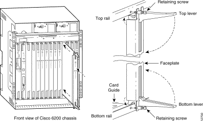
Step 6 Ensure that the card's upper and lower insertion/extraction levers engage the upper and lower front rails of the enclosure. See Figure 1.

Step 7 Press the upper lever down and the lower lever up at the same time. (This action electrically connects the card to the backplane.)
Step 8 Secure the card to the enclosure by tightening the upper and lower retaining screws.
Step 9 Repeat Step 2 through Step 8 to install additional cards.
When a card is inserted, the green POWER LED on its faceplate turns on. The card performs an internal confidence test. Each card's READY LED turns on when the card successfully completes its test.
Step 10 Install blank faceplates to cover any unused slots in the chassis. Like cards, faceplates are each held in place by two retaining screws.
 | Warning Blank faceplates and cover panels serve three important functions: they prevent exposure to hazardous voltages and currents inside the chassis; they contain electromagnetic interference (EMI) that might disrupt other equipment; and they direct the flow of cooling air through the chassis. Do not operate the system unless all cards, faceplates, front covers, and rear covers are in place. |
Step 11 How to proceed:
 | Warning The ports labeled "Ethernet," "ENET," "ETH1," "ETH2," "CNSL," and "Serial Port" are safety extra-low voltage (SELV) circuits. SELV circuits should be connected only to other SELV circuits. Because the DSL circuits are treated like telephone-network voltage, avoid connecting the SELV circuit to the telephone network voltage (TNV) circuits. |
Software configuration for new SLCs is performed using either the Cisco 6200 Manager software (a graphical user interface (GUI) management application) or the command line interface (CLI) to the Cisco 6200. See the User Guide for the Cisco 6200 Manager for instructions on using the GUI.
This section explains how to use CLI commands to configure the SLC interfaces on a Cisco 6200 system. You can follow these steps before or after you insert the SLC into its slot in the chassis.
To configure an SLC, you must be in global configuration mode. If you are already in this mode, start with Step 3.
Step 1 Enter the enable command and then enter the password to go into privileged mode:
c6200> enable
Enter Password:
Step 2 Enter the configure command and press Return to accept "terminal," the default.
c6200# configure
Configuring from terminal, memory, or network [terminal]?

c6200(config)#
Step 3 If you already inserted the card you want to configure into its slot, go to Step 4. If the card is not in the slot, use this step to preconfigure the card.
Enter the c6200 card command and specify a slot number and card type. The SLC goes into a slot with a number in the range 5 to 14 and has a card type of slc1-8-cap or slc1-8-dmt. Each card has eight ports, numbered 0 to 7. In the following example, an SLC 8CAP is being preconfigured for slot 5.
c6200(config)# c6200 card 5 slc1-8-cap
Step 4 Enter the interface dsl command and specify the card and port you want to configure. In this example, you configure port 0 of the SLC in slot 5.
c6200(config)# interface dsl 5/0
Step 5 Specify a subscriber name. In this example, the subscriber name "boston" is specified. If you skip this step, the system provides a default subscriber name in the form port-type slot/port, for example, "dsl 5/0."
c6200(config-if)# dsl subscribername boston
Step 6 Specify downstream and upstream bit rates, which in this example have been set to 1600 and 272 kbps, respectively:
c6200(config-if)# dsl bitrate downstream 1600 upstream 272
Step 7 Activate the configuration by entering the no shutdown command and return to the global configuration prompt by entering the end command.
c6200(config-if)# no shutdown
c6200(config-if)# end
c6200(config)#
Repeat Step 4 through Step 7 for each of the interfaces that you want to configure, and then follow the step below to save the configuration to nonvolatile memory. If you do not save it, the configuration will be lost when the device is rebooted.
Step 8 To save the configuration, use the end command to return to privileged EXEC mode, and copy the running configuration to the startup configuration:
c6200# end
c6200# copy running-config startup-config
Step 9 In addition to saving the configuration to the startup configuration, you may want to copy it to a PCMCIA Flash memory card. The following command copies the startup configuration to a file named "6200-config" on the PCMCIA card in slot 0.
c6200# copy startup-config slot0:6200-config
If you are replacing an MPC, follow these steps after you complete the steps in the "Card Installation" section. This procedure does not interrupt the flow of data.
Step 1 At the console, look for this prompt and answer No:
Would you like to enter the initial configuration dialog? [yes]: no
Step 2 At the Router> or c6200> prompt, enter enable and the password to access privileged EXEC mode:
C6200> enable

Password:
c6200#
Step 3 Enter the dir command to display the names of the files on the PCMCIA card in slot 0:
6200# dir slot0:

-#- -length- -----date/time------ name
1    1166308 Jul 06 1998 14:33:55 c6200-dcm-mz.113-1.DA1.bin
2       1121 Jul 06 1998 14:44:30 6200-config

19410616 bytes available (1167688 bytes used)
Step 4 Enter the copy command to copy the configuration file from the PCMCIA card to running-config in memory:
6200# copy slot0:6200-config running-config

6200#
%SYS-5-CONFIG: Configured from slot0:6200-config by console #
Step 5 Enter another copy command to copy the configuration file from the PCMCIA card to startup-config in NVRAM:
6200# copy slot0:6200-config startup-config

Building configuration...
Step 6 To enable the interfaces, enter the configure terminal command, followed by the configuration commands shown in this example:
6200# configure terminal

Enter configuration commands, one per line.  End with CNTL/Z.
6200(config)# int e0/0

6200(config-if)# no shut

6200(config-if)# int e0/1

6200(config-if)# no shut

6200(config-if)# int atm 1/0

6200(config-if)# no shut

6200(config-if)# exit

6200(config)# exit

6200# copy running-config startup-config

Building configuration...
[OK]
6200#
The procedure for removing MPCs, NTCs, and SLCs is the same. It is not necessary to disconnect power before removing any card from the Cisco 6200 DSLAM.
 | Caution Static voltages as low as 30 volts can cause latent damage to circuitry. Be sure to observe all standard anti-static procedures (for example, wear a grounding strap). |
Step 1 Disconnect any cables connected to the card you are about to remove. If you are disconnecting a single-mode OC-3 or STM-1 card, read the following warnings.
 | Warning Class 1 laser product. |
 | Warning Because invisible laser radiation may be emitted from the aperture of the port when no cable is connected, avoid exposure to laser radiation and do not stare into open apertures. |
The fiber optic communication channels in the single-mode OC-3 and STM-1 cards (NTC OC3-SM and NTC STM1-SM) operate with laser energy, which can be harmful, especially to the eyes. During normal operation this energy is confined to the cable and presents no danger. To avoid injury when connecting or disconnecting optical channels, observe these precautions: always disconnect the card from the backplane before connecting or disconnecting optical cables; always keep the protective cap on the optic connector when the connector is not in use; and never look into an optical cable or connector.
Step 2 Unscrew the upper and lower retaining screws that secure the card to the chassis.
Step 3 Grasp the upper and lower extraction levers. Pull up on the upper lever while pushing down on the lower lever. This action disengages the card from the connectors on the backplane.
Step 4 Slide the card out of the chassis.
Step 5 Place the card on an antistatic surface. If it will be out of the chassis for any length of time, put it in an antistatic shielding bag or in a box lined with antistatic material.
Step 6 In the empty slot, install another card of the same type or a blank faceplate.
 | Warning Blank faceplates and cover panels serve three important functions: they prevent exposure to hazardous voltages and currents inside the chassis; they contain electromagnetic interference (EMI) that might disrupt other equipment; and they direct the flow of cooling air through the chassis. Do not operate the system unless all cards, faceplates, front covers, and rear covers are in place. |
If you are removing the card permanently, update the system configuration using the Cisco 6200 Manager (GUI) or the command line interface (CLI). For instructions, see
The power bays are located at front of the chassis, near the top. The bay on the left is wired to power circuit A; the bay on the right is wired to power circuit B. (The circuits are identified at the power terminals on the backplane.)
It is not necessary to disconnect power before inserting a PEM into the Cisco 6200 chassis. Follow these steps:
Step 1 Ensure that the circuit breaker on the PEM is turned to OFF (0).
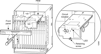
Step 2 Use a Phillips screwdriver to remove the front panel that partially covers the power bays. Two Phillips-head quarter-turn fasteners are recessed into the face of the panel; insert the screwdriver and turn the fastener 90 degrees in either direction to release it.
Step 3 Engage the sheet-metal carrier that forms the top of the PEM with the brackets on each side of the power bay. (See Figure 2.)
Step 4 Firmly push the PEM all the way into the power bay to ensure that the power connectors mate.
Step 5 Tighten the captive screw on the faceplate of the PEM to secure the PEM to the chassis.
Step 6 If the chassis is connected to power, turn the circuit breaker on the PEM to ON. A green LED on the faceplate comes on to indicate that the PEM is providing power to the chassis.
Step 7 Replace the front panel and use a Phillips screwdriver to fasten it in place. You can look through the rectangular opening in the panel as you engage the fasteners. Turn the fastener 90 degrees in either direction to secure it.

If you remove a PEM from a Cisco 6200 chassis in which a second PEM is installed and providing power to the chassis, the chassis continues to operate normally. If you plan to remove the only operating PEM from a chassis, you should shut down the system first.
Follow these steps to shut down and turn off the DSLAM.
Step 1 Before shutting down the Cisco 6200, use the copy command to save any configuration changes to NVRAM, and also, if you wish, to a PCMCIA Flash card. (See the command reference chapter of the Cisco 6200 User Guide for instructions on using copy.)
Step 2 Allow any copy or write operations involving Flash media (PCMCIA slots or boot Flash) to complete.
Step 3 Turn the circuit breakers on both PEMs to OFF (0).
Follow these steps to remove a PEM from the Cisco 6200 chassis. If you are removing the only operating PEM in an active system, follow the previous procedure, "Shutting Down the Cisco 6200," before performing these steps.
Step 1 Ensure that the circuit breaker on the PEM you are about to remove is turned to OFF (0).
Step 2 Use a Phillips screwdriver to remove the front panel that partially covers the power bays. Two Phillips-head quarter-turn fasteners are recessed into the face of the panel; insert the screwdriver and turn the fastener 90 degrees in either direction to release it.
Step 3 Unscrew the retaining screw in the PEM faceplate.
Step 4 Grasp the PEM by the handle on its faceplate and pull it out of the chassis.
 | Warning
Hold the PEM by the sheet-metal carrier (top and front) only. Internal components may be hot. |
Step 5 Replace the front panel and use the Phillips screwdriver to fasten it in place. You can look through the rectangular opening in the panel as you engage the fasteners. Turn the fastener 90 degrees in either direction to secure it.
The fan tray is located at the bottom of the chassis, behind a removable panel. You need a Phillips screwdriver to remove and replace the panel.
 | Caution The Cisco 6200 cooling fans must run continuously. The system may suffer thermal damage if the fans stop for more than 10 minutes. (At ambient temperatures above 104° F (40° C), thermal damage may occur sooner.) |
Follow these steps to install the fan tray:
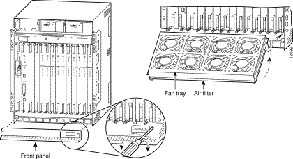
Step 1 Use a Phillips screwdriver to remove the panel that covers the fan tray (see Figure 3).
Step 2 Hold the fan tray so that the fans are on top, the air filter is on the bottom, and the wide edge of the tray is facing away from you.
Step 3 Tilting the front edge of the fan tray downward, insert the wide edge of the tray so that it clears the bottom lip of the chassis. (See Figure 3.)
Step 4 Engage the edges of the fan tray with the guides on either side of the slot in the chassis. Ensure that the edges of the fan tray rest on top of the guides in the slot.
Step 5 Slide the tray gently into place. Press firmly to ensure that the power connectors mate. If the chassis is receiving power, you will hear the fans start to turn.
Step 6 Use the Phillips screwdriver to replace the panel over the fan tray.

If you must remove the fan tray from a Cisco 6200, replace it within a few minutes. If that is not possible, it is recommended that you shut down the system and turn off power to avoid thermal damage.
 | Caution It is important that the system's cooling fans run continuously. The system might suffer thermal damage if the fans stop for more than ten minutes. (At ambient temperatures above 104° F (40° C), thermal damage can occur sooner.) |
You need a Phillips screwdriver to perform this procedure.
Follow these steps to remove the fan tray:
Step 1 Use a Phillips screwdriver to remove the panel that covers the fan tray area at the bottom front of the chassis.
Step 2 Grasp the fan tray with both hands and gently pull it toward you. If the fans are running, you will hear them slow down as the tray disengages from its power connector.
Step 3 As you pull the fan tray from the chassis, tilt the front edge downwards so the wide rear edge clears the lip at the bottom of the chassis. (See Figure 3.)
Cleaning and replacement of the air filter in the fan tray is covered in the Cisco 6200 User Guide in Chapter 6, "Preventive Maintenance."
This procedure tells you how to attach dangler cables to the 50-pin Champ connectors on the back of the Cisco 6200 DSLAM. (The Champs provide unshielded twisted pair (UTP) connections for subscriber traffic.)
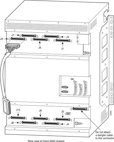
The dangler cables are numbered J1 through J10. Figure 4 and Table 1 show which Champ connector each dangler cable should be attached to.

Each dangler cable serves the subscriber line card (SLC) in a particular slot. The dangler cables correspond to the SLC slots as shown in Table 1.
| J1 | Slot 5 | J6 | Slot 10 |
| J2 | Slot 6 | J7 | Slot 11 |
| J3 | Slot 7 | J8 | Slot 12 |
| J4 | Slot 8 | J9 | Slot 13 |
| J5 | Slot 9 | J10 | Slot 14 |
You need a Phillips screwdriver to install the dangler cables. Follow these steps:
Step 1 Use a Phillips screwdriver to unfasten one of the two metal panels that cover the Champ connectors on the back of the Cisco 6200. Each panel is held in place by six Phillips-head quarter-turn fasteners. Turn each fastener 90 degrees in either direction to release it.
Step 2 Attach dangler cables to the five connectors (see Figure 4). Secure the cables with the wire clips attached to the backplane connectors.
Step 3 Route the dangler cables toward the sides of the chassis: two to one side, three to the other.
Step 4 Replace the metal cover and use a Phillips screwdriver to fasten it in place. Turn each fastener 90 degrees in either direction to secure it.
Step 5 Repeat this procedure, if necessary, to install dangler cables behind the other panel.
Follow these steps to remove dangler cables from the back of the Cisco 6200 DSLAM. You need a Phillips screwdriver to perform this procedure.
Step 1 Use a Phillips screwdriver to unfasten one of the two metal panels that cover the dangler cables on the back of the Cisco 6200. Each panel is held in place by six Phillips-head quarter-turn fasteners. Turn each fastener 90 degrees in either direction to release it.
Step 2 Unfasten the two wire clips holding each dangler cable in place, and then pull the cable off the connector.
Step 3 Replace the metal cover and use a Phillips screwdriver to fasten it in place. Turn each fastener 90 degrees in either direction to secure it.
Step 4 Repeat this procedure, if necessary, to remove the dangler cables behind the other panel.
Cisco Connection Online (CCO) is Cisco Systems' primary, real-time support channel. Maintenance customers and partners can self-register on CCO to obtain additional information and services.
Available 24 hours a day, 7 days a week, CCO provides a wealth of standard and value-added services to Cisco's customers and business partners. CCO services include product information, product documentation, software updates, release notes, technical tips, the Bug Navigator, configuration notes, brochures, descriptions of service offerings, and download access to public and authorized files.
CCO serves a wide variety of users through two interfaces that are updated and enhanced simultaneously: a character-based version and a multimedia version that resides on the World Wide Web (WWW). The character-based CCO supports Zmodem, Kermit, Xmodem, FTP, and Internet e-mail, and it is excellent for quick access to information over lower bandwidths. The WWW version of CCO provides richly formatted documents with photographs, figures, graphics, and video, as well as hyperlinks to related information.
You can access CCO in the following ways:
For a copy of CCO's Frequently Asked Questions (FAQ), contact cco-help@cisco.com. For additional information, contact cco-team@cisco.com.

![]()
![]()
![]()
![]()
![]()
![]()
![]()
![]()
Posted: Tue Dec 17 21:30:07 PST 2002
All contents are Copyright © 1992--2002 Cisco Systems, Inc. All rights reserved.
Important Notices and Privacy Statement.