|
|

Product Number: CSC-CCTL=
The first generation ciscoBus controller card (CSC-CCTL) provides two functions for the AGS+ router: it interconnects the system bus (Multibus) with the ciscoBus for routing packets from interfaces on the ciscoBus to interfaces on the system bus and performs packet-switching functions on the ciscoBus using an onboard processor, instead of the system processor. The CSC-CCTL features a 16-million-instructions-per-second processor to provide high-speed, autonomous switching of data packets on the ciscoBus.
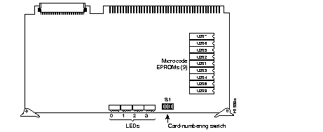
The CSC-CCTL card is required for operation when ciscoBus network interface cards (CSC-FCI, CSC-HSCI, and CSC-MEC) are installed. Figure 1 is shows the CSC-CCTL card viewed from the component side. If the CSC-C2FCI, CSC-C2MEC, or CSC-C2HSCI interface cards are required, the CSC-CCTL card cannot be used; the second-generation ciscoBus controller card (CSC-CCTL2) is required instead.

Electrostatic discharge (ESD) is a discharge of stored static electricity that can damage equipment and impair electrical circuitry. It occurs when electronic components are improperly handled and can result in complete or intermittent failures.
Following are guidelines for preventing ESD damage:
 | Caution For safety, periodically check the resistance value of the antistatic strap. The measurement should be within the range of 1 and 10 Mohms. |
Your CSC-CCTL card should be a Revision E (or later) card running Microcode Version 1.0 (or later). You can display the version of the microcode using the EXEC command show controller cBus when the CSC-CCTL card is installed. The CSC-CCTL card revision number is located on the part number label affixed to one of the ejectors on the card. (If you cannot find the label, it is not a Revision E card, or later.) If your system does not display the correct microcode version, contact a service representative.
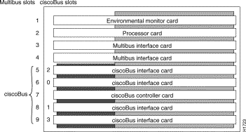
The chassis card cage (see Figure 2) has nine Multibus slots and five ciscoBus slots. (The five ciscoBus slots can accept Multibus cards if ciscoBus cards are not desired.) Because the chassis requires the CSC-ENVM card and a processor card at a minimum, seven Multibus slots are available. If ciscoBus cards are used, the center ciscoBus slot (slot 7 in Figure 2) is used for the CSC-CCTL card, leaving four slots available for ciscoBus interface cards.
Table 1 lists the ciscoBus interface cards that are compatible with the CSC-CCTL controller card.
| ciscoBus Card | Interface Cards |
|---|---|
| CSC-CCTL | CSC-HSCI/Ultra |
| CSC-FCI | |
| CSC-MEC |
Table 2 lists the card number-switch setting (S1) for the CSC-CCTL ciscoBus controller card. Ensure that your CSC-CCTL card is set for card number 0. No Multibus interface cards can be numbered as Card 0 with a CSC-CCTL card in the system. The Card 0 designation is reserved for the CSC-CCTL card by default.
| Card No. | S1-1 | S1-2 | S1-3 | S1-4 |
|---|---|---|---|---|
| 0 | off | off | off | off |
The system card cage, shown in Figure 2, has nine slots, five of which are designated ciscoBus slots. The center ciscoBus slot is reserved for the ciscoBus controller card, leaving four ciscoBus slots available for ciscoBus interface cards.
The system uses a slot priority scheme that assigns a priority to each ciscoBus card according to the ciscoBus slot in which the card resides. The card in ciscoBus slot 0 receives the highest ciscoBus priority, while the card in ciscoBus slot 3 receives the lowest ciscoBus priority.
Slot priorities are set to accommodate the amount of traffic generated by each interface card and the amount of card buffering required. Each ciscoBus interface card is placed in a specific slot with regard to other ciscoBus interface cards, if any. The order of priority is the same for both first- and second-generation ciscoBus controllers, except that the cards with the C2 designation can only be used with the CSC-CCTL2.
Following is a list of ciscoBus interface cards in order of priority, from highest to lowest:
Install CSC-MEC or C2MEC cards in the lowest-numbered slots, beginning with slot 0 (which has the highest priority), followed by CSC-C2CTR cards. After all CSC-MEC and CSC-C2CTR cards are installed, install CSC-HSCI and C2HSCI cards with the APP-LHS applique in the lowest-numbered available slots. Follow with the CSC-FCI and C2FCI cards. Next, install CSC-C2FCIT cards. Last, install the CSC-HSCI and C2HSCI cards with the APP-ULA (UltraNet) applique. Always install cards in the lowest-numbered available slot. For example, if using only CSC-C2HSCI cards (with APP-ULA), place the first in slot 0, the second in slot 1, and so forth.

Following is the procedure for accessing the chassis interior.
Step 1 Turn OFF power to the chassis and unplug it from AC power.
Step 2 If the chassis is rack mounted, disconnect all external cables from the chassis rear panel. Note where these cables were connected, for reinstallation.
Step 3 Remove the chassis from the rack and transfer it to a desktop or work table.
Step 4 If you will need to handle any electronic components (cards, and so forth), attach appropriate ESD protection and attach the AC power cord, but to prevent a shock hazard, make certain the chassis power is OFF.
Step 5 To access cards in the card cage, loosen the two thumbscrews and remove the front panel from the chassis. (See Figure 3.) If you wish to access cards in the card cage only, skip the next step.
Step 6 To access other system components, locate and remove the seven No. 1 Phillips screws securing the top cover. (See Figure 3.) Set the top cover and screws aside.

Following is the procedure for installing the CSC-CCTL card:
Step 1 Turn OFF power to the system, but to channel ESD voltages to ground, do not unplug it.
Step 2 Follow the procedure in the section "Chassis Access Procedure."
Step 3 Check that the card number has been set to 0. Switch S1 (see Figure 1 for location) assigns the card number used by the system processor card. Table 2 describes the settings for the card number when the switch is oriented as shown in Figure 1.
Step 4 Insert the CSC-CCTL into the middle ciscoBus slot (the seventh slot from the top). See Figure 2 for an illustration of slot placement. The fit will be snug.
 | Caution Failure to place the CSC-CCTL card in the correct slot can inhibit system operation. |
Step 5 At power up, all LEDs are ON, indicating the card is active. After the system is booted, and the CSC-CCTL firmware has completed its discovery phase, refer to the following section "CSC-CCTL Card LEDs."
Step 6 After you install the CSC-CCTL and your interface cards, use the EXEC command show controller cbus to display the names and unit numbers of all controller and interface cards and their microcode version numbers.
Following is a partial sample display:
show controller cbus
Step 7 When the card tests successfully, turn OFF power to the system and replace the front access panel.
Figure 4 illustrates the LEDs that are on when a card is present in a corresponding ciscoBus slot. (The orientation of Figure 4 is looking at the front edge of the card installed in the card cage.) The numbers above the LEDs indicate the ciscoBus slot number. Depending upon the slot in which the ciscoBus card is installed (slot 0 through 3), the corresponding LED will come on to indicate a card in that slot. Some ciscoBus cards have appliques that require power from the card to which they attach. If these appliques are not connected correctly, the corresponding LED on the CSC-CCTL will not come on. All other LEDs momentarily flash at power on, but are not currently used.


|
|