|
|

Product Numbers: CSC-CCTL2=, CSC-CCTL2U, MC-CCTL2-V11.0, MC-CCTL2-V11.1=, MC-CCTL2-V11.2=
This document contains the following instructions:
The CSC-CCTL2 card is required for operation when C2 (second-generation ciscoBus) network interface cards are installed (CSC-C2MEC, CSC-C2HSCI, CSC-C2FCI, CSC-C2FCIT, and CSC-C2CTR).
If you are upgrading from a first-generation ciscoBus controller (CSC-CCTL), all existing ciscoBus interface cards must also be upgraded at the same time to the minimum system requirements described herein. Generally, first- and second-generation ciscoBus controllers and interface cards do not interoperate. You also may need to upgrade microcode on Multibus interfaces for compatibility with System Software Release 9.1, which is the minimum software version required for CSC-CCTL2 operation.
The sections in this document include the following:
The ciscoBus II controller card (CSC-CCTL2) provides two functions for the AGS+ router: it serves to interconnect the system bus (Multibus) with the ciscoBus for routing packets between ciscoBus and system bus interfaces, and it performs packet-switching functions on the ciscoBus using its onboard processor and 512 kilobytes of dedicated packet memory. The CSC-CCTL2 uses bit-slice processing to provide high-speed autonomous switching of data packets on the ciscoBus without having to access the system processor across the Multibus. The operating microcode resides on an EPROM in socket U6. (See Figure 1.) You replace this single EPROM to upgrade the CCTL2 microcode.

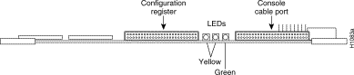
The LEDs on the CCTL2 card indicate when an interface is present in a ciscoBus slot. The front edge of the CCTL2 card contains a bank of five LEDs as shown in Figure 2: one red LED for each slot in the ciscoBus and one green OK LED to indicate a successful boot procedure. One red LED will be on for each correctly connected ciscoBus card using the correct version of microcode. The green OK LED will not be on if the card is incorrectly connected or if the microcode on that ciscoBus card is the wrong version. Figure 2 shows the LEDs on the CCTL2 card. The numbers above the LEDs (0 through 3 from right to left) indicate the ciscoBus slot number assigned to that LED.


The CSC-CCTL2 card is required for operation when C2 (second-generation ciscoBus) network interface cards are installed (CSC-C2MEC, CSC-C2HSCI, CSC-C2FCI, CSC-C2FCIT, and CSC-C2CTR). These cards are described in the section "ciscoBus Configuration" on page 5.
Before installing the CSC-CCTL2, ensure that your existing system components meet the compatibility requirements and that you have the necessary parts and tools you will need to perform the installation without interruption. If you are upgrading a CSC-CCTL to a CSC-CCTL2, ensure that you have all the necessary microcode upgrades for existing cards.
The router system must meet the following requirements:
You can display the type of processor card (CSC/3 or CSC/4) installed and the current software version with the EXEC command show version. The current system software version is displayed in the first line of the output, and the processor card information is displayed on the twelfth line, followed by a list of the installed interface cards. A sample of the display, which shows a system running System Software Release 9.1(1), follows:
router# show version
GS Software (GS3), Version 9.1(1)
Copyright (c) 1986-1992 by cisco Systems, Inc.
Compiled Wed 29-Jul-92 17:02
System Bootstrap, Version 4.5(0.5)
router uptime is 22 days, 12 hours, 23 minutes
System restarted by power-on
System image file is "router-system", booted via tftp from 131.108.1.111
CSC4 (68040) processor with 16384K bytes of memory.
X.25 software.
Bridging software.
1 MCI controller (2 Ethernet, 0 Serial).
1 cBus controller.
1 MEC controller (6 Ethernet).
Environmental Controller.
(text omitted)
You can display a description of the current ciscoBus controller and ciscoBus interface cards with the EXEC command show controller cbus. The ciscoBus controller type is displayed, followed by the descriptions of each ciscoBus interface card, the ciscoBus slot in which it is installed, the controller type, and the microcode version of each.
The following example of the show controller cbus display shows a first-generation ciscoBus controller (CSC-CCTL), which is a controller type 3.0. The microcode on each card is compatible with the first-generation ciscoBus controller, CSC-CCTL, since each version is earlier than 10.0.
router# show cont cbus
cBus 1, controller type 3.0, microcode version 2.0
  128 Kbytes of main memory, 32 Kbytes cache memory
  (text omitted)
 FDDI 0, controller type 4.1, microcode version 2.0
  Interface 0 - Fddi0, station address 0000.0c01.7bbd (bia 0000.0c01.7bbd)
  (text omitted)
 HSCI 1, controller type 10.0, microcode version 1.0
  Interface 6 - Hssi0, electrical interface is Hssi DTE
 MEC 3, controller type 5.1, microcode version 2.4
  Interface 18 - Ethernet2, station address 0000.0c02.a03c
  (text omitted)
The next example of the show controller cbus display shows a second-generation ciscoBus controller (CSC-CCTL2), which is a controller type 6.0. The microcode on each interface shown in the display is compatible with the second-generation ciscoBus controller, CSC-CCTL2, since each version is than 10.0 or later. (Version 10.0 or later is compatible.)
router# show cont cbus
cBus 1, controller type 6.0, microcode version 10.0
  512 Kbytes of main memory, 128 Kbytes cache memory
  	(text omitted)
 FDDI-T 0, controller type 7.1, microcode version 10.1
  Interface 0 - Fddi0, station address 0000.0c02.6aa3 (bia
	(text omitted)
 CTR 1, controller type 9.0, microcode version 10.1
  Interface 1 - TokenRing0, station address 0000.3040.e004 (bia
	(text omitted)
 HSCI 2, controller type 10.0, microcode version 10.1
  Interface 8 - Hssi0, electrical interface is Hssi DTE
    	(text omitted)
 MEC 3, controller type 5.1, microcode version 10.1
  Interface 10 - Ethernet2, station address 0000.0c02.61b7
	(text omitted)
For descriptions of fields and additional commands, refer to the router products configuration publication.
The Microcode Release Note publication (Document Number 78-1069-nn) provides the latest information on both the recommended and minimum required microcode versions for using all cards with System Software Release 8.2 through 9.1. If the latest version implements features that you are not using in your system, and you already have the minimum required version installed, there is no requirement to update the microcode. However, new microcode versions occasionally fix bugs and provide performance enhancements in addition to implementing new features. You will obtain maximum performance and reliability by upgrading to the recommended version. Refer to the latest Microcode Release Note for current microcode requirements and recommendations, and for a microcode revision history for each card, which describes the new features, fixed bugs, and compatibility requirements for each revision.
Before installing the CSC-CCTL2, ensure that all ciscoBus interface cards are the C2 series (meaning all have Microcode Version 10.0 or later installed), that any new ciscoBus cards you are installing will not exceed the maximum port limits for ciscoBus interfaces, and that the cards will be placed in the correct order of priority in the ciscoBus slots. The following sections describe how to determine all of these requirements.
All ciscoBus interface cards, which are listed in Table 1, contain card-specific microcode that determines whether each card is compatible with the first- or second-generation ciscoBus controller. General compatibility guidelines are as follows:
The C2 designator added to the name of a ciscoBus interface card indicates that the card is running Microcode Version 10.0 or later and is, therefore, compatible with the CSC-CCTL2. With the exception of a Revision 5.0 CSC-MEC card (see "Note" following), the first- and second-generation ciscoBus interface cards are otherwise the same. For example, you can upgrade a Revision 5.1 CSC-MEC to a CSC-C2MEC by replacing the microcode with Version 10.0 or later. When you upgrade the microcode on the CSC-MEC card to Version 10.0, the name of the card also changes from CSC-MEC to CSC-C2MEC to indicate that it is CCTL2-compatible. When you replace a CSC-CCTL ciscoBus controller with a CSC-CCTL2 ciscoBus controller, you must upgrade the microcode on all ciscoBus interface cards to Microcode Version 10.0 or later.
| CCTL Controller | CCTL2 Controller | Description |
|---|---|---|
| CSC-CCTL | CSC-CCTL2 | ciscoBus controller |
| CSC-FCI | CSC-C2FCI | Fiber Distributed Data Interface (FDDI) |
| - | CSC-C2FCIT | FDDI with translational bridging |
| CSC-HSCI | CSC-C2HSCI | High-Speed Serial Interface (HSSI) |
| - | CSC-C2CTR | ciscoBus Token Ring interface, 4/16Mbps |
| CSC-MEC | CSC-C2MEC1 | Multiport Ethernet Controller |
You can display a description of the current ciscoBus controller and ciscoBus interface cards with the EXEC command show controller cbus as described on page 4.
The system card cage, shown in Figure 3, has nine slots, five of which are designated ciscoBus slots. The center ciscoBus slot is reserved for the ciscoBus controller card, leaving four ciscoBus slots available for ciscoBus interface cards.
The system uses a slot priority scheme that assigns a priority to each ciscoBus card according to the ciscoBus slot in which the card resides. The card in ciscoBus slot 0 receives the highest ciscoBus priority, while the card in ciscoBus slot 3 receives the lowest ciscoBus priority.
Slot priorities are set to accommodate the amount of traffic generated by each interface card and the amount of card buffering required. Each ciscoBus interface card is placed in a specific slot with regard to other ciscoBus interface cards, if any. The order of priority is the same for both first- and second-generation ciscoBus controllers, except that the cards with the C2 designation can only be used with the CSC-CCTL2.
Following is a list of ciscoBus interface cards in order of priority, from highest to lowest:
Install CSC-MEC or C2MEC cards in the lowest-numbered slots, beginning with slot 0 (which has the highest priority), followed by CSC-C2CTR cards. After all CSC-MEC and CSC-C2CTR cards are installed, install CSC-HSCI and C2HSCI cards with the APP-LHS applique in the lowest-numbered available slots. Follow with the CSC-FCI and C2FCI cards. Next, install CSC-C2FCIT cards. Last, install the CSC-HSCI and C2HSCI cards with the APP-ULA (UltraNet) applique. Always install cards in the lowest-numbered available slot. For example, if using only CSC-C2HSCI cards (with APP-ULA), place the first in slot 0, the second in slot 1, and so forth.
The amount of processing some cards require, and the available chassis space for the larger appliques, can limit the maximum number and types of ports you can install in a single chassis. The maximum numbers of ciscoBus interface port combinations are shown in Table 2. Exceeding these limits may degrade performance on any or all installed ciscoBus interfaces and is not recommended.
| (C2)MEC Ports (Cards) | C2FCIT/(C2)FCI Ports (Cards) | (C2)HSSI Ports (Cards) | C2CTR Ports (Cards) | ||||
|---|---|---|---|---|---|---|---|
| 24 | (4) | 0 | (0) | 0 | (0) | 0 | (0) |
| 18 | (3) | 1 | (1) | 0 | (0) | 0 | (0) |
| 18 | (3) | 0 | (0) | 1 | (1) | 0 | (0) |
| 18 | (3) | 0 | (0) | 0 | (0) | 4 | (1) |
| 12 | (2) | 2 | (2) | 0 | (0) | 0 | (0) |
| 12 | (2) | 1 | (1) | 1 | (1) | 0 | (0) |
| 12 | (2) | 1 | (1) | 0 | (0) | 4 | (1) |
| 12 | (2) | 0 | (0) | 2 | (2) | 0 | (0) |
| 12 | (2) | 0 | (0) | 1 | (1) | 4 | (1) |
| 12 | (2) | 0 | (0) | 0 | (0) | 8 | (2) |
| 6 | (1) | 1 | (1) | 0 | (0) | 6 | (2) |
| 6 | (1) | 0 | (0) | 1 | (1) | 6 | (2) |
| 6 | (1) | 3 | (3) | 0 | (0) | 0 | (0) |
| 6 | (1) | 0 | (0) | 3 | (3) | 0 | (0) |
| 6 | (1) | 2 | (2) | 1 | (1) | 0 | (0) |
| 6 | (1) | 2 | (2) | 0 | (0) | 4 | (1) |
| 6 | (1) | 0 | (0) | 2 | (2) | 4 | (1) |
| 6 | (1) | 1 | (1) | 1 | (1) | 4 | (1) |
| 6 | (1) | 1 | (1) | 2 | (2) | 0 | (0) |
| 0 | (0) | 3 | (3) | 0 | (0) | 2 | (1) |
| 0 | (0) | 2 | (2) | 1 | (1) | 2 | (1) |
| 0 | (0) | 1 | (1) | 2 | (2) | 2 | (1) |
| 0 | (0) | 0 | (0) | 3 | (3) | 2 | (1) |
| 0 | (0) | 4 | (4) | 0 | (0) | 0 | (0) |
| 0 | (0) | 3 | (3) | 1 | (1) | 0 | (0) |
| 0 | (0) | 2 | (2) | 2 | (2) | 0 | (0) |
| 0 | (0) | 1 | (1) | 3 | (3) | 0 | (0) |
| 0 | (0) | 0 | (0) | 4 | (4) | 0 | (0) |
The router uses a card numbering scheme to identify cards in the chassis, and an interface addressing scheme to identify the ports (interfaces) on each card. Each Multibus interface card and the ciscoBus controller card (CSC-CCTL2) have a unique card number, which you set with switch S1 on each card. The system processor uses the card numbers to assign interface addresses to the ports on each card and to control traffic across the Multibus. Because the CSC-CCTL2 controls the traffic between the Multibus and all ciscoBus cards, only the ciscoBus controller card needs a card number. The card number of the CSC-CCTL2 is always 0, which is the factory default; no Multibus cards can be set for card number 0. The location of the card-numbering switch is shown in Figure 1.
Table 3 lists the card-number switch setting (S1) for the CSC-CCTL2 ciscoBus controller card. Ensure that your CSC-CCTL2 card is set for card number 0. No Multibus interface cards can be numbered as Card 0 with a CSC-CCTL card in the system. The Card 0 designation is reserved for the CSC-CCTL2 card by default.
| Card No. | S1-1 | S1-2 | S1-3 | S1-4 |
|---|---|---|---|---|
| 0 | Off | Off | Off | Off |
At startup, the system polls each Multibus interface card, beginning with the lowest card number, and assigns a sequential interface address to each port (interface) on each card. When all Multibus interfaces are assigned, the system proceeds to the ciscoBus and continues the interface address sequence as it polls the ciscoBus cards according to the ciscoBus slot priority. (Refer to the section "Slot Priority" on page 6.)
These numbering schemes allow the system to distinguish each interface card while sequentially numbering like interfaces (such as Ethernet interfaces on CSC-MCIs and CSC-MECs). Table 4 is an example of how the system assigns Ethernet interface addresses in a chassis with one CSC-MCI 2E2T (two Ethernet/two serial) card and two CSC-MEC6 (six Ethernet ports each) cards. The CSC-MCI is a Multibus card, and the CSC-MEC is a ciscoBus card; therefore, the CSC-MCI interface addresses are assigned first.
| Card | Port on Card | Interface Address Assigned |
|---|---|---|
| CSC-MCI | Port 0 | Ethernet 0 |
| Port 1 | Ethernet 1 | |
| First CSC-MEC | Port 0 | Ethernet 2 |
| Port 1 | Ethernet 3 | |
| Port 2 | Ethernet 4 | |
| Port 3 | Ethernet 5 | |
| Port 4 | Ethernet 6 | |
| Port 5 | Ethernet 7 | |
| Second CSC-MEC | Port 0 | Ethernet 8 |
| Port 1 | Ethernet 9 | |
| Port 2 | Ethernet 10 | |
| Port 3 | Ethernet 11 | |
| Port 4 | Ethernet 12 | |
| Port 5 | Ethernet 13 |
The CSC-CCTL2 can be installed in any router that meets the criteria described in the section "System Requirements" on page 3. Only one ciscoBus controller card can be installed in a chassis, and it always resides in the center ciscoBus slot (slot 7 of the card cage, shown in Figure 3).
The chassis has a total power budget of 300 watts (W). The total power dissipation of the individual interface and processor cards must not exceed 300W. In chassis shipped before October 1, 1991, the total power cannot exceed 260W. (These chassis used a 5 amp (A) circuit breaker, rather than the 7.5A breaker used in the current chassis.) Following is a sample calculation for adding two CSC-MEC6 cards (all values in watts).
One CSC-ENVM card | 1 x 10 = 10 |
|---|---|
| One CSC/4 processor card | 1 x 35 = 35 |
| One CSC-CCTL2 card | 1 x 29 = 29 |
| One CSC-FCI card | 1 x 50 = 50 |
| One CSC-MCI 2E card | 1 x 28 = 28 |
| 14 Ethernet transceivers | 14 x 4 = 56 (12 additional for the new MEC cards) |
| Power requirement of present system | 208 |
| Available power budget | 300 - 208 = 98 |
| Add two CSC-MEC cards | 2 x 22 = 44 |
| New cards within power budget | 44 < 98 (New CSC-MEC cards can be installed.) |
| Card/Applique Assemblies | Power Requirement (in Watts) |
|---|---|
| CSC/4 | 35 |
| CSC/3 | 31 |
| CSC-ENVM | 10 |
| CSC-MC+ | 3 |
| CSC-MCI1 | 28 |
| CSC-SCI | 20 |
| CSC-R16M | 34 |
| CSC-1R and -2R | 30 |
| CSC-CCTL2 | 34 |
| CSC-C2FCIT with applique | 36 |
| CSC-CSFCI with applique | 50 |
| CSC-C2MECx2 | 22 |
| CSC-CSHSCI | 48 |
| CSC-C2CTR-2 with applique | 30 |
| CSC-C2CTR-4 with appliques | 42 |
| CSC-CCTL | 29 |
| CSC-FCI with applique | 50 |
| CSC-MECx2 | 22 |
| CSC-HSCI with applique | 48 |
When new hardware components are installed, the system automatically invokes the setup command facility the first time the system is started. You must use setup to configure new interfaces, or you can exit setup and configure new interfaces with the configure EXEC command. If you are adding new interfaces at the same time you are installing the CSC-CCTL2, be prepared with the information you will need to configure each new interface, such as the protocols you plan to route, IP addresses and subnet masks, and whether or not you will use bridging. For step-by-step instructions for using the setup command facility and configuring the interfaces, refer to the Router Products Getting Started Guide.
To access the card cage and install your CSC-CCTL2 card, you need only remove the front access panel on the router. If you are removing the panel for the first time, you will need a large flat-blade screwdriver to loosen the thumbscrews, which are torqued before shipping the first time.
If you are upgrading from a CSC-CCTL first-generation ciscoBus controller, you will need a microcode upgrade kit for each ciscoBus interface card currently installed in your router. If you do not have an upgrade kit for one or more cards, contact a service representative for assistance.
Electrostatic discharge (ESD) is a discharge of stored static electricity that can damage equipment and impair electrical circuitry. It occurs when electronic components are improperly handled and can result in complete or intermittent failures.
Following are guidelines for preventing ESD damage:
 | Caution For safety, periodically check the resistance value of the antistatic strap. The measurement should be within the range of 1 and 10 Mohms. |
The following describes the procedures for installing the CSC-CCTL2 card in your router chassis, and for verifying correct installation when you restart the system by checking the LEDs on cards in the card cage. Before proceeding, ensure that your system meets the requirements listed in the section "Installation Prerequisites" on page 3.
The CSC-CCTL2 is installed in the system card cage, which you access by removing the chassis front access panel shown in Figure 4. You must install the CSC-CCTL2 in the center ciscoBus slot (Multibus slot 7) shown in Figure 3. Your system will not function if the CSC-CCTL2 is placed in any other slot.
| Caution To prevent electrostatic discharge damage when removing and replacing cards, follow the ESD procedures described earlier. |
Step 1 Ensure that the chassis is firmly seated on a stable surface. The high-performance cards that connect to the ciscoBus require substantial force to slide them into the card cage and seat them properly.
Step 2 Turn OFF the system power at the power switch on the rear of the chassis.
| Caution Installing or removing cards when the chassis power is on will result in severe damage to the card. |
Step 3 On the front of the chassis, loosen (but do not attempt to remove) the two thumb fasteners on the access panel (see Figure 4), then remove the panel to expose the system card cage.

Step 4 Slip on an ESD wrist strap and connect it to the chassis as previously described. To channel ESD voltages to ground, ensure that the power cable is connected, but that the power is OFF.
Step 5 You may need to disconnect internal cables from other cards in the card cage if they are routed in front of the ciscoBus card slot. If so, be sure that all cables are labeled to avoid mixing interfaces when you reconnect them.
Step 6 Remove the existing ciscoBus controller card (if any) from the middle ciscoBus slot. (See Figure 3.) Use your thumbs to pull the ejector tabs out and away from the card. Open both ejectors at the same time.
Step 7 Check switch S1 on the new CSC-CCTL2 card and verify that the card number is set correctly to 0. Card numbers are described in the section "Card and Interface Numbering" on page 8.
Step 8 Hold the CSC-CCTL2 card by the ejector tabs and the card edges, component-side up, with the bus edge away from you. Install the CSC-CCTL2 card into the middle ciscoBus slot (the seventh slot from the top, shown in Figure 3). Place your thumbs on the ejector tabs, and push the card in firmly until the ejector tabs close.
| Caution Failure to place the CSC-CCTL2 card in the correct slot prevents the correct operation of your system. |
Step 9 Reconnect any cables that were removed for the installation.
Step 10 If you are upgrading from a CSC-CCTL, replace the microcode on all existing ciscoBus interface cards before restarting the system. For installation instructions, refer to the documentation that accompanies each upgrade kit.
If you also need to upgrade the microcode on Multibus cards, do so before installing any new cards in the chassis. For installation instructions, refer to the documentation that accompanies each upgrade kit.
Step 11 After all necessary upgrades are performed, and the cards are replaced, install any new interface cards. When installing ciscoBus cards, place cards into ciscoBus slots according to the priority scheme described in the section "Slot Priority" on page 6.
Step 12 When all ciscoBus interface cards are installed and/or upgraded, proceed to the next section, "Checking the Installation." Do not replace the front access panel; the panel must be off to observe the LEDs on the cards.
Following is the procedure to verify correct installation:
Step 1 Turn ON the system power. All five LEDs on the CSC-CCTL2 should be on while the system is booting. If they do not, do the following:
Step 2 After the system boots, check the LEDs on the CSC/3 (see Figure 5) or the CSC/4 (see Figure 6) system processor card. The far right OK LED should be on; the other two LEDs should be off. If the far right LED is not on, or if either of the other two LEDs is on or flashing, a system error has been detected. If this happens, do the following:

Step 3 When the system is operational, verify that the far right, green OK LED on the CSC-CCTL2 is on and remains on. If it does not, proceed with the installation. If it appears that the OK LED is faulty, contact a service representative for card replacement instructions.
Step 4 Check the four red LEDs on the CSC-CCTL2. Ensure that the LED for each occupied ciscoBus card is on. (For LED descriptions, see the section "Card Overview" on page 2.) (The interfaces on some cards do not light until the interface is configured as up; refer to the documents that accompany individual interface cards for expected LED behavior.)
In general, if any CSC-CCTL2 LEDs do not come on, do the following:
Step 5 Check the system console terminal and ensure that the system banner is displayed, followed by a list of the installed hardware. (See page 4 for an example of this display, which is the same as the output for the show version command.)
Step 6 When the LEDs indicate correct installation, replace the chassis front access cover and finger-tighten the two thumb screws.
When new hardware is installed, the system automatically defaults to the setup command facility. You can either remain in setup and answer each prompt, or exit from setup and configure any new interfaces with the configure command. If you have no new interfaces to configure, exit from setup by answering no to the following prompt:
Continue with configuration dialog [yes]? no
When the system is configured and running, use the show controller cbus command to display the name, controller type (type 6.0 for a CCTL2), microcode version, and interfaces on each card in the ciscoBus. For complete descriptions of other show commands, refer to the router products configuration publication.
This completes the CSC-CCTL2 installation.
The microcode on the CSC-CCTL2 resides on a single component in socket U6 on the card. You may need to replace the microcode when upgrading your system software or to add new functionality to the card when it becomes available. To display the current microcode version installed on the CSC-CCTL2 and the ciscoBus interface cards, use the show controller cbus command (described in the section "System Requirements" on page 3). Refer to Figure 7 for the location of U6 while performing the following steps.
Step 1 Follow steps 1 through 6 in the section "Installation" beginning on page 12.
Step 2 Place the removed card on an antistatic mat or foam.
Step 3 Referring to Figure 7, locate the component in socket U6. Note the orientation of the notch; the new component must be inserted with the same notch orientation.
Step 4 Use a chip extractor to remove the component from its socket. If you do not have a chip extractor available, you can use the tip of a small flat-blade screwdriver to gently pry the component out of its socket.
Step 5 Install the new component in socket U6. Verify the notch orientation and be careful not to bend or crush any of the pins when inserting the new components. If any pins are bent, use needlenose pliers to straighten the pins, then carefully reinsert the component. If a pin breaks, contact a service representative for a replacement.
| Caution If the EPROM is inserted backwards and then power is turned ON, the EPROM will be damaged. |
Step 6 Replace the card in the card cage. Place your thumbs on the ejector tabs and push the card in firmly until it snaps into place and is firmly seated in the slot.
Step 7 Reconnect any internal ribbon cables that had to be removed from other cards. Be sure to match the interface numbers labeled on the cables with the interface ports on the cards.
Step 8 Turn ON power to the system for an installation check.
Step 9 Check the LEDs on the CSC-CCTL2, which are described in the section "Card Overview" on page 2. If the microcode component is not installed correctly, or if any of the pins were bent during installation, the green OK LED on the CSC-CCTL2 will not light. If this happens, remove the component, straighten any bent pins, then reinsert it and try again.
Step 10 When the LEDs are on correctly, replace the front access panel and finger-tighten the thumb screws.
To display the new microcode version, use the show controller cbus command. For descriptions and examples of additional commands, refer to the router products configuration publication.
This completes the EPROM upgrade procedure.
Cisco Information Online (CIO) is Cisco Systems' primary, real-time support channel. You can use your product serial number to activate CIO for a single user during your warranty period. Maintenance customers and partners can self-register on CIO to obtain additional content and services.
Available 24 hours a day, 7 days a week, CIO provides a wealth of standard and value-added services to Cisco's customers and business partners. CIO services include product information, software updates, release notes, technical tips, the Bug Navigator, configuration notes, brochures, descriptions of service offerings, and download access to public and authorized files.
CIO serves a wide variety of users through two interfaces that are updated and enhanced simultaneously--a character-based version and a multimedia version that resides on the World Wide Web (WWW). The character-based CIO (called "CIO Classic") supports Zmodem, Kermit, Xmodem, FTP, Internet e-mail, and fax download options, and is excellent for quick access to information over lower bandwidths. The WWW version of CIO provides richly formatted documents with photographs, figures, graphics, and video, as well as hyperlinks to related information.
You can access CIO in the following ways:
http://www.cisco.com.
cio.cisco.com (198.92.32.130).
For a copy of CIO's Frequently Asked Questions (FAQ), contact cio-help@cisco.com. For additional information, contact cio-team@cisco.com.
If you are a network administrator and need personal technical assistance with a Cisco product that is under warranty or covered by a maintenance contract, contact Cisco's Technical Assistance Center (TAC) at 800 553-2447, 408 526-7209, or tac@cisco.com. To obtain general information about Cisco Systems, Cisco products, or upgrades, contact 800 553-6387, 408 526-7208, or cs-rep@cisco.com.

|
|