|
|

Table Of Contents
Route Switch Processors and Supervisor Engines
Supported Chassis, Line Cards, and Modules
Unsupported Hardware and Features
Supervisor Engine 720 and Supervisor Engine 32
Front-Panel Controls (RSP720, Sup720, Sup32)
Front-Panel LEDs (RSP720, Sup720, Sup32)
Route Switch Processors and Supervisor Engines
This chapter describes the route switch processors and supervisor engines supported on Cisco 7600 series routers and provides instructions for performing basic tasks on the modules. It contains the following sections:
•
Overview
•
Note
See Table 2-1 for a list of the route switch processor and supervisor engine configurations supported on Cisco 7600 series routers. Be sure to review the release notes for the software version running on your router for information about any restrictions and limitations that might apply.
Overview
The supervisor engine or route switch processor (RSP) is a module that is installed in one of the card slots in the router. The supervisor engine or RSP provides switching and local and remote management for the router and also contains the uplink ports for the router. Both types of modules (supervisor engine and RSP) perform the same functions in the router.
Note
Cisco 7600 series routers support the following types of RSPs and supervisor engines:
•
•
•
•
Although the router can operate with a single supervisor engine or RSP, you can also install a second redundant module (of the same type) in the chassis. Only one module is active at a time. The second module acts as a "standby," serving as a backup if the active module fails.
Note
The supervisor engine or RSP contains the following integrated daughter cards that perform forwarding and routing and provide the protocols supported on the router. Several configurations of daughter cards are supported (as shown in Table 2-1).
•
–
–
–
–
Note
•
–
–
Table 2-1 lists the RSP and supervisor engine configurations supported on Cisco 7600 series routers. Specific combinations of processors and modules may not be supported in your chassis. See the release notes for your software version for information about supported combinations.
Route Switch Processor 720
This section describes the Route Switch Processor 720 (RSP720), which is the newest type of supervisor engine available for Cisco 7600 series routers. The Cisco 7600 RSP720 consists of a full-size board and two integrated daughter cards: the MSFC4 and a PFC3C or PFC3CXL. The RSP720 has an integrated switch fabric that interconnects all of the line cards in the Cisco 7600 router with point-to-point 20-Gbps full-duplex serial channels.
Note
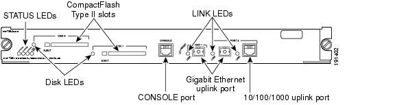
The RSP720 is supported on all Cisco 7600 routers (including enhanced chassis) except the Cisco 7603 and the Cisco OSR-7609.Figure 2-1 shows the RSP720-3C-GE front panel, which is the same as the RSP720-3CXL-GE front panel. See Table 2-2 and Table 2-3 for information about the front-panel controls and LEDs.
Figure 2-1 Route Switch Processor 720 (RSP720-3C-GE) Front Panel
RSP720 Features
The RSP720 provides several new features and enhancements, which are summarized here. For details, see the Cisco 7600 Series Router Cisco IOS Software Configuration Guide, Release 12.2SR.
•
•
•
•
Supported Chassis, Line Cards, and Modules
The RSP720 supports the following Cisco 7600 chassis, line cards and modules:
•
•
•
•
•
•
Unsupported Hardware and Features
The following hardware and features are not supported by the RSP720:
•
•
•
Supervisor Engine 720 and Supervisor Engine 32
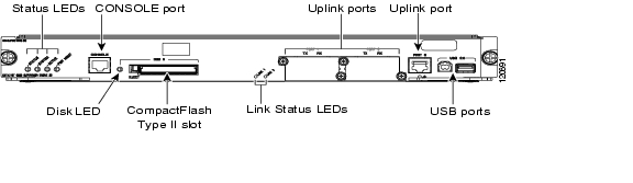
The following figures ( Figure 2-2, Figure 2-3, and Figure 2-4) show the front panel on the Supervisor Engine 720 (Sup720) and Supervisor Engine 32 (Sup32). The tables that follow describe the controls and LEDs on the RSP720, Sup720, and Sup32. For information on the Supervisor Engine 2 controls and LEDs, see the "Supervisor Engine 2" section.
Figure 2-2 Supervisor Engine 720 (WS-SUP720) Front Panel
Figure 2-3 Supervisor Engine 32 (WS-SUP32-GE-3B) Front Panel
Figure 2-4 Supervisor Engine 32 (WS-SUP32-10GE-3B) Front Panel
Front-Panel Controls (RSP720, Sup720, Sup32)
Table 2-2 describes the front-panel controls on the Route Switch Processor 720, the Supervisor Engine 720, and the Supervisor Engine 32.
Table 2-2 RSP720, Sup720, and Sup32 Front-Panel Controls
Indicate the status of various functions on the module (see Table 2-3).
Restarts the router. Use a ballpoint pen tip or other small, pointed object to access the Reset button. Not all modules have a Reset button.
Disk SlotsOne or two slots for flash memory cards. Do not remove the card from the slot while the disk LED is on. See the "Using Flash Memory Cards" section on page 3-12 for information about working with flash memory.
Provides access to the router. The port is an EIA/TIA-232 asynchronous, serial connection with hardware flow control and an RJ-45 connector. See the "Connecting to the Console Port" section on page 3-9 for instructions on connecting to the console port.
On the RSP720, the console port allows you to access either the switch processor (SP) or the route processor (RP).
Used to connect the router to other network devices. The uplink ports are configurable with small form-factor pluggable (SFP) or XENPAK optics modules. See the "Connecting to the Uplink Ports" section on page 3-10 for more information.
Each USB port can function as a console port or security key.
Front-Panel LEDs (RSP720, Sup720, Sup32)
LEDs on the front panel of the supervisor engine or route switch processor (RSP) show the status of the processor and other components installed in the router. Table 2-3 lists the LED functions on the Route Switch Processor 720, Supervisor Engine 720, and Supervisor Engine 32. See Table 2-5 for a list of LED functions on the Supervisor Engine 2.
Table 2-3 RSP720, Sup720, and Sup32 LEDs
Green
All diagnostics pass; the module is operational (normal initialization sequence).
Orange
The module is booting or running diagnostics (normal initialization sequence).
Yellow
Minor hardware problems.
Red
An overtemperature condition occurred. (A major threshold has been exceeded during environmental monitoring.)
Green
All chassis environmental monitors are reporting OK.
Orange
The module is powering up or a minor hardware fault has occurred.
Red
Major hardware problem.
The temperature of the supervisor engine or RSP has exceeded the major temperature threshold.
Blinking Red
Continuous backplane stall.
Green
The supervisor engine or RSP is operational and active.
Orange
The supervisor engine or RSP is powering up or is in standby mode.
Green
Sufficient power is available for all modules installed in the router.
Orange
The supervisor engine or RSP is powering up or has minor hardware problems.
Red
Major hardware problem.
Green
The disk is active. Do not remove the disk while the light is on or the file may be corrupted.
Green
The port is operational.
Orange
The port is disabled.
Flashing orange
The port is bad.
Off
The supervisor engine or RSP is powering up or the port is enabled and there is no link.
1 The SYSTEM and PWR MGMT LEDs on a redundant supervisor engine or RSP are synchronized to the active module.
Supervisor Engine 2
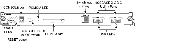
This section describes the Supervisor Engine 2 (see Figure 2-5), which has slightly different controls and features than the Supervisor Engine 720 and Supervisor Engine 32. Table 2-4 describes the controls and features on the front panel and Table 2-5 describes the LEDs.
Note
Figure 2-5 Supervisor Engine 2 Front Panel
Table 2-4 Supervisor Engine 2 Front-Panel Controls
Indicate the status of various functions on the module (see Table 2-5).
Restarts the router. Use a ballpoint pen tip or other small, pointed object to access the Reset button.
Provides access to the router either locally (with a console terminal) or remotely (with a modem). The port is an EIA/TIA-232 asynchronous, serial connection with hardware flow control and an RJ-45 connector. See the "Connecting to the Console Port" section on page 3-9 for instructions on connecting to the console port.
Enables you to connect a terminal to the console port using either the cable and adapters provided with the router (switch in the in position, factory default) or a Catalyst 5000 Supervisor Engine III console cable and adapter, not provided (switch in the out position).
PCMCIA flash memory card slot. Do not remove the card from the slot while the disk LED is on. See the "Using Flash Memory Cards" section on page 3-12 for information about working with flash memory.
A visual approximation of the current traffic load across the backplane.
Used to connect the router to another network device. Two dual-port Gigabit Ethernet uplink ports operate in full-duplex mode only. You can configure the ports with any combination of copper, short-wave (SX), long-wave/long-haul (LX/LH), extended-reach (ZX), and CWDM 1000BASE-X Gigabit Interface Converters (GBICs). See the "Connecting to the Uplink Ports" section on page 3-10 for more information.
Table 2-5 lists the LED functions on the Supervisor Engine 2.
Table 2-5 Supervisor Engine 2 LEDs
Green
All diagnostics pass; the module is operational (normal initialization sequence).
Orange
The module is booting or running diagnostics (normal initialization sequence).
An overtemperature condition has occurred. (A minor threshold has been exceeded during environmental monitoring.)
Red
Diagnostic test failed; the module is not operational. (The fault occurred during the initialization sequence.)
An overtemperature condition has occurred. (A major threshold has been exceeded during environmental monitoring.)
Green
All chassis environmental monitors are reporting OK.
Orange
The power supply or power supply fan failed.
Incompatible power supplies are installed.
The redundant clock failed.
One VTT2 module has failed or the VTT module temperature minor threshold has been exceeded.3
Red
Two VTT modules failed or the VTT module temperature major threshold has been exceeded.3
The temperature of the supervisor engine major threshold has been exceeded.
Green
The supervisor engine is operational and active.
Orange
The supervisor engine is in standby mode.
Green
Sufficient power is available for all modules.
Orange
Sufficient power is not available for all modules.
If the system is operational, the switch load meter indicates (as an approximate percentage) the current traffic load over the backplane.
The PCMCIA LED is lit when no PCMCIA card is in the slot and goes off when you insert a card.
Green
The port is operational.
Orange
The link has been disabled by software.
Flashing orange
The link is bad and has been disabled due to a hardware failure.
Off
No signal is detected.
1 The SYSTEM and PWR MGMT LED indications on a redundant supervisor engine are synchronized to the active engine.
2 VTT = voltage termination. The VTT module terminates signals on the system switching bus.
3 If no redundant supervisor engine is installed and there is a VTT module minor or major overtemperature condition, the system shuts down.
![]()
![]()
![]()
![]()
![]()
![]()
![]()
![]()
Posted: Tue Jan 15 03:35:09 PST 2008
All contents are Copyright © 1992--2008 Cisco Systems, Inc. All rights reserved.
Important Notices and Privacy Statement.