|
|

Table Of Contents
Specifying the Interface Address on a SPA
Modifying the Interface MTU Size
Creating a Permanent Virtual Circuit
Creating a PVC on a Point-to-Point Subinterface
Configuring a PVC on a Multipoint Subinterface
Configuring RFC 1483 Bridging for PVCs
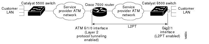
Configuring Layer 2 Protocol Tunneling Topology
Configuring RFC 1483 Bridging for PVCs with IEEE 802.1Q Tunneling
Configuring ATM RFC 1483 Half-Bridging
Configuring ATM Routed Bridge Encapsulation
Configuring RFC 1483 Bridging of Routed Encapsulations
Configuring Aggregate WRED for PVCs
Creating and Configuring Switched Virtual Circuits
Configuring Traffic Parameters for PVCs or SVCs
Configuring Virtual Circuit Classes
Configuring Virtual Circuit Bundles
Configuring Multi-VLAN to VC Support
Configuring Link Fragmentation and Interleaving with Virtual Templates
Configuring the Distributed Compressed Real-Time Protocol
Configuring Automatic Protection Switching
Configuring SONET and SDH Framing
Configuring for Transmit-Only Mode
Configuring AToM VP Cell Mode Relay Support
Configuring QoS Features on ATM SPAs
Shutting Down and Restarting an Interface on a SPA
Shutting Down an ATM Shared Port Adapter
Verifying the Interface Configuration
Verifying Per-Port Interface Status
Monitoring Per-Port Interface Statistics
Basic Interface Configuration Example
Permanent Virtual Circuit Configuration Example
PVC on a Point-to-Point Subinterface Configuration Example
PVC on a Multipoint Subinterface Configuration Example
RFC 1483 Bridging for PVCs Configuration Example
RFC 1483 Bridging for PVCs with IEEE 802.1Q Tunneling Configuration Example
ATM RFC 1483 Half-Bridging Configuration Example
ATM Routed Bridge Encapsulation Configuration Example
Precedence-Based Aggregate WRED Configuration Example
DSCP-Based Aggregate WRED Configuration Example
Switched Virtual Circuits Configuration Example
Traffic Parameters for PVCs or SVCs Configuration Example
Virtual Circuit Classes Configuration Example
Virtual Circuit Bundles Configuration Example
Link Fragmentation and Interleaving with Virtual Templates Configuration Example
Distributed Compressed Real-Time Protocol Configuration Example
Automatic Protection Switching Configuration Example
SONET and SDH Framing Configuration Example
Layer 2 Protocol Tunneling Topology with a Cisco 7600 and Cisco 7200 Configuration Example
Cisco 7600 Basic Back-to-Back Scenario Configuration Example
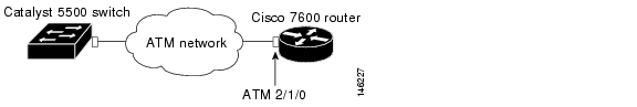
Catalyst 5500 Switch and Cisco 7600 Series Routers in Back-to-Back Topology Configuration Example
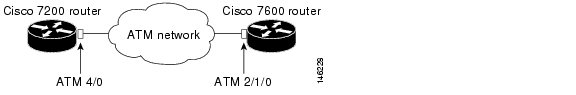
Cisco 7600 and Cisco 7200 in Back-to-Back Topology Configuration Example
Configuring the ATM SPAs
This chapter provides information about configuring the ATM SPAs on the Cisco 7600 series router. It includes the following sections:
•
Verifying the Interface Configuration
For information about managing your system images and configuration files, refer to the Cisco IOS Configuration Fundamentals Configuration Guide and Cisco IOS Configuration Fundamentals Command Reference publications that correspond to your Cisco IOS software release.
For more information about the commands used in this chapter, see first Chapter 40, "SIP, SSC, and SPA Commands," which documents new and modified commands, and then the Cisco 7600 Series Router Command Reference publication. Also refer to the related Cisco IOS Release 12.2 software command reference and master index publications. For more information about accessing these publications, see the "Related Documentation" section on page xlviii.
Configuration Tasks
This section describes the most common configurations for the ATM SPAs on a Cisco 7600 series router. It contains procedures for the following configurations:
•
•
•
•
•
•
•
•
•
•
•
•
•
•
•
•
•
•
•
•
•
•
•
•
•
•
•
Required Configuration Tasks
The ATM SPA interface must be initially configured with an IP address to allow further configuration. Some of the required configuration commands implement default values that might or might not be appropriate for your network. If the default value is correct for your network, then you do not need to configure the command. To perform the basic configuration of each interface, use the following procedure beginning in global configuration mode:
Step 1
Router(config)# interface atm slot/subslot/port
Enters interface configuration mode for the indicated port on the specified ATM SPA.
Step 2
Router(config-if)# ip address address mask [secondary]
(Optional in some configurations) Assigns the specified IP address and subnet mask to the interface. Repeat the command with the optional secondary keyword to assign additional, secondary IP addresses to the port.
Step 3
Router(config-if)# description string
(Optional) Assigns an arbitrary string, up to 80 characters long, to the interface. This string can identify the purpose or owner of the interface, or any other information that might be useful for monitoring and troubleshooting.
Step 4
Router(config-if)# no shutdown
Enables the interface.
Note
Step 5
Router(config-if)# end
Exits interface configuration mode and returns to privileged EXEC mode.
Specifying the Interface Address on a SPA
Two ATM SPAs can be installed in a SIP. SPA interface ports begin numbering with "0" from left to right. Single-port SPAs use only the port number 0. To configure or monitor SPA interfaces, you need to specify the physical location of the SIP, SPA, and interface in the CLI. The interface address format is slot/subslot/port, where:
•
•
•
The following example shows how to specify the first interface (0) on a SPA installed in the first subslot of a SIP (0) installed in chassis slot 3:
Router(config)# interface serial 3/0/0This command shows a serial SPA as a representative example, however the same slot/subslot/port format is similarly used for other SPAs (such as ATM and POS) and other non-channelized SPAs.
For more information about identifying slots and subslots, see the "Identifying Slots and Subslots for SIPs, SSCs, and SPAs" section on page 4-2.
Modifying the Interface MTU Size
The maximum transmission unit (MTU) values might need to be reconfigured from their defaults on the ATM SPAs to match the values used in your network.
Interface MTU Configuration Guidelines
When configuring the interface MTU size on an ATM SPA, consider the following guidelines.
The Cisco IOS software supports several types of configurable MTU options at different levels of the protocol stack. You should ensure that all MTU values are consistent to avoid unnecessary fragmentation of packets. These MTU values are the following:
•
•
•
All devices on a particular physical medium must have the same MPLS MTU value to allow proper MPLS operation. Because MPLS labels are added on to the existing packet and increase the packet's size, choose appropriate MTU values so as to avoid unnecessarily fragmenting MPLS-labeled packets.
If the IP MTU or MPLS MTU values are currently the same size as the interface MTU, changing the interface MTU size also automatically sets the IP MTU or MPLS MTU values to the new value. Changing the interface MTU value does not affect the IP MTU or MPLS MTU values if they are not currently set to the same size as the interface MTU.
Different encapsulation methods and the number of MPLS MTU labels add additional overhead to a packet. For example, Subnetwork Access Protocol (SNAP) encapsulation adds an 8-byte header, IEEE 802.1Q encapsulation adds a 2-byte header, and each MPLS label adds a 4-byte header. Consider the maximum possible encapsulations and labels that are to be used in your network when choosing the MTU values.
Tip
Note
Interface MTU Configuration Task
To change the MTU values on the ATM SPA interfaces, use the following procedure beginning in global configuration mode:
Step 1
Router(config)# interface atm slot/subslot/port
Enters interface configuration mode for the indicated port on the specified ATM SPA.
Step 2
Router(config-if)# mtu bytes
(Optional) Configures the maximum transmission unit (MTU) size for the interface. The valid range for bytes is from 64 to 9216 bytes, with a default of 4470 bytes. As a general rule, do not change the MTU value unless you have a specific application need to do so.
Note
Step 3
Router(config-if)# ip mtu bytes
(Optional) Configures the MTU value, in bytes, for IP packets on this interface. The valid range for an ATM SPA is 64 to 9288, with a default value equal to the MTU value configured in Step 2.
Step 4
Router(config-if)# mpls mtu bytes
(Optional) Configures the MTU value, in bytes, for MPLS-labeled packets on this interface. The valid range for an ATM SPA is 64 to 9216 bytes, with a default value equal to the MTU value configured in Step 2.
Note
Step 5
Router(config-if)# end
Exits interface configuration mode and returns to privileged EXEC mode.
Verifying the MTU Size
To verify the MTU sizes for an interface, use the show interface, show ip interface, and show mpls interface commands, as in the following examples:
Router# show interface atm 4/1/0ATM4/1/0 is up, line protocol is upHardware is SPA-4XOC3-ATM, address is 000d.2959.d5ca (bia 000d.2959.d5ca)MTU 4470 bytes, sub MTU 4470, BW 149760 Kbit, DLY 80 usec,reliability 255/255, txload 1/255, rxload 1/255Encapsulation ATM, loopback not setEncapsulation(s): AAL54095 maximum active VCs, 0 current VCCsVC idle disconnect time: 300 seconds0 carrier transitionsLast input never, output never, output hang neverLast clearing of "show interface" counters neverInput queue: 0/75/0/0 (size/max/drops/flushes); Total output drops: 0Queueing strategy: fifoOutput queue: 0/0 (size/max)30 second input rate 0 bits/sec, 0 packets/sec30 second output rate 0 bits/sec, 0 packets/sec0 packets input, 0 bytes, 0 no bufferReceived 0 broadcasts, 0 runts, 0 giants, 0 throttles0 input errors, 0 CRC, 0 frame, 0 overrun, 0 ignored, 0 abort0 packets output, 0 bytes, 0 underruns0 output errors, 0 collisions, 0 interface resets0 output buffer failures, 0 output buffers swapped outRouter# show ip interface atm 4/1/0ATM4/1/0 is up, line protocol is upInternet address is 200.1.0.2/24Broadcast address is 255.255.255.255Address determined by non-volatile memoryMTU is 4470 bytesHelper address is not setDirected broadcast forwarding is disabledMulticast reserved groups joined: 224.0.0.9Outgoing access list is not setInbound access list is not setProxy ARP is enabledSecurity level is defaultSplit horizon is enabledICMP redirects are always sentICMP unreachables are always sentICMP mask replies are never sentIP fast switching is enabledIP fast switching on the same interface is disabledIP Flow switching is disabledIP Feature Fast switching turbo vectorIP Null turbo vectorVPN Routing/Forwarding "vpn2600-2"IP multicast fast switching is enabledIP multicast distributed fast switching is disabledIP route-cache flags are Fast, CEFRouter Discovery is disabledIP output packet accounting is disabledIP access violation accounting is disabledTCP/IP header compression is disabledRTP/IP header compression is disabledProbe proxy name replies are disabledPolicy routing is disabledNetwork address translation is disabledWCCP Redirect outbound is disabledWCCP Redirect exclude is disabledBGP Policy Mapping is disabledRouter# show mpls interface atm 4/1/0 detailInterface ATM3/0:IP labeling enabled (ldp)LSP Tunnel labeling not enabledMPLS operationalMPLS turbo vectorMTU = 4470ATM labels: Label VPI = 1Label VCI range = 33 - 65535Control VC = 0/32To view the maximum possible size for datagrams passing out the interface using the configured MTU value, use the show atm interface atm command:
Router# show atm interface atm 4/1/0Interface ATM4/1/0:AAL enabled: AAL5, Maximum VCs: 4096, Current VCCs: 2Maximum Transmit Channels: 0Max. Datagram Size: 4528PLIM Type: SONET - 155000Kbps, TX clocking: LINECell-payload scrambling: ONsts-stream scrambling: ON8359 input, 8495 output, 0 IN fast, 0 OUT fast, 0 out dropAvail bw = 155000Config. is ACTIVECreating a Permanent Virtual Circuit
To use a permanent virtual circuit (PVC), configure the PVC in both the router and the ATM switch. PVCs remain active until the circuit is removed from either configuration. To create a PVC on the ATM interface and enter interface ATM VC configuration mode, perform the following procedure beginning in global configuration mode:
Step 1
Router(config)# interface atm slot/subslot/port
or
Router(config)# interface atm slot/subslot/port.subinterface
Enters interface or subinterface configuration mode for the indicated port on the specified ATM SPA.
Step 2
Router(config-if)# ip address address mask
Assigns the specified IP address and subnet mask to the interface or subinterface.
Step 3
Router(config-if)# atm tx-latency milliseconds
(Optional) Configures the default transmit latency for VCs on this ATM SPA interface. The valid range for milliseconds is from 1 to 200, with a default of 100 milliseconds.
Step 4
Router(config-if)# pvc [name] vpi/vci [ilmi | qsaal]
Configures a new ATM PVC by assigning its VPI/VCI numbers and enters ATM VC configuration mode. The valid values for vpi/vci are:
•
•
You can also configure the following options:
•
•
•
Note
Step 5
Router(config-if-atm-vc)# protocol protocol {protocol-address | inarp} [[no] broadcast]
Configures the PVC for a particular protocol and maps it to a specific protocol-address.
•
•
•
•
Step 6
Router(config-if-atm-vc)# inarp minutes
(Optional) If using Inverse ARP, configures how often the PVC transmits Inverse ARP requests to confirm its address mapping. The valid range is 1 to 60 minutes, with a default of 15 minutes.
Step 7
Router(config-if-atm-vc)# encapsulation aal5snap
(Optional) Configures the ATM adaptation layer (AAL) and encapsulation type. The default and only supported type is aal5snap.
Step 8
Router(config-if-atm-vc)# tx-limit buffers
(Optional) Specifies the number of transmit buffers for this VC. The valid range is from 1 to 57343, with a default value that is based on the current VC line rate and on the latency value that is configured with the atm tx-latency command.
Note
Step 9
Router(config-if-atm-vc)# end
Exits ATM VC configuration mode and returns to privileged EXEC mode.
Verifying a PVC Configuration
To verify the configuration of a particular PVC, use the show atm pvc command:
Router# show atm pvc 1/100ATM3/0/0: VCD: 1, VPI: 1, VCI: 100UBR, PeakRate: 149760AAL5-LLC/SNAP, etype:0x0, Flags: 0xC20, VCmode: 0x0OAM frequency: 0 second(s), OAM retry frequency: 1 second(s)OAM up retry count: 3, OAM down retry count: 5OAM Loopback status: OAM DisabledOAM VC status: Not ManagedILMI VC status: Not ManagedInARP frequency: 15 minutes(s)Transmit priority 6InPkts: 94964567, OutPkts: 95069747, InBytes: 833119350, OutBytes: 838799016InPRoc: 1, OutPRoc: 1, Broadcasts: 0InFast: 0, OutFast: 0, InAS: 94964566, OutAS: 95069746InPktDrops: 0, OutPktDrops: 0CrcErrors: 0, SarTimeOuts: 0, OverSizedSDUs: 0, LengthViolation: 0, CPIErrors: 0Out CLP=1 Pkts: 0OAM cells received: 0F5 InEndloop: 0, F5 InSegloop: 0, F5 InAIS: 0, F5 InRDI: 0F4 InEndloop: 0, F4 InSegloop: 0, F4 InAIS: 0, F4 InRDI: 0OAM cells sent: 0F5 OutEndloop: 0, F5 OutSegloop: 0, F5 OutRDI: 0F4 OutEndloop: 0, F4 OutSegloop: 0, F4 OutRDI: 0OAM cell drops: 0Status: UPVC 1/100 doesn't exist on 7 of 8 ATM interface(s)
Tip
Creating a PVC on a Point-to-Point Subinterface
Use point-to-point subinterfaces to provide each pair of routers with its own subnet. When you create a PVC on a point-to-point subinterface, the router assumes it is the only point-to-point PVC that is configured on the subinterface, and it forwards all IP packets with a destination IP address in the same subnet to this VC. To configure a point-to-point PVC, perform the following procedure beginning in global configuration mode:
Step 1
Router(config)# interface atm slot/subslot/port.subinterface point-to-point
Creates the specified point-to-point subinterface on the given port on the specified ATM SPA, and enters subinterface configuration mode.
Step 2
Router(config-subif)# ip address address mask
Assigns the specified IP address and subnet mask to this subinterface.
Step 3
Router(config-subif)# pvc [name] vpi/vci [ilmi | qsaal]
Configures a new ATM PVC by assigning its VPI/VCI numbers and enters ATM VC configuration mode. The valid values for vpi/vci are:
•
•
You can also configure the following options:
•
•
•
Note
Step 4
Router(config-if-atm-vc)# protocol protocol protocol-address [[no] broadcast]
Configures the PVC for a particular protocol and maps it to a specific protocol-address.
•
•
•
The protocol command also has an inarp option, but this option is not meaningful on point-to-point PVCs that use a manually configured address.
Step 5
Router(config-if-atm-vc)# encapsulation aal5snap
(Optional) Configures the ATM adaptation layer (AAL) and encapsulation type. The default and only supported type is aal5snap.
Note
Step 6
Router(config-if)# end
Exits interface configuration mode and returns to privileged EXEC mode.
Verifying a Point-to-Point PVC Configuration
To verify the configuration of a particular PVC, use the show atm pvc command:
Router# show atm pvc 3/12ATM3/1/0.12: VCD: 3, VPI: 3, VCI: 12UBR, PeakRate: 149760AAL5-LLC/SNAP, etype:0x0, Flags: 0xC20, VCmode: 0x0OAM frequency: 0 second(s), OAM retry frequency: 1 second(s)OAM up retry count: 3, OAM down retry count: 5OAM Loopback status: OAM DisabledOAM VC status: Not ManagedILMI VC status: Not ManagedInARP frequency: 15 minutes(s)Transmit priority 6InPkts: 3949645, OutPkts: 3950697, InBytes: 28331193, OutBytes: 28387990InPRoc: 1, OutPRoc: 1, Broadcasts: 0InFast: 0, OutFast: 0, InAS: 3949645, OutAS: 3950697InPktDrops: 0, OutPktDrops: 0CrcErrors: 0, SarTimeOuts: 0, OverSizedSDUs: 0, LengthViolation: 0, CPIErrors: 0Out CLP=1 Pkts: 0OAM cells received: 0F5 InEndloop: 0, F5 InSegloop: 0, F5 InAIS: 0, F5 InRDI: 0F4 InEndloop: 0, F4 InSegloop: 0, F4 InAIS: 0, F4 InRDI: 0OAM cells sent: 0F5 OutEndloop: 0, F5 OutSegloop: 0, F5 OutRDI: 0F4 OutEndloop: 0, F4 OutSegloop: 0, F4 OutRDI: 0OAM cell drops: 0Status: UP
Tip
Configuring a PVC on a Multipoint Subinterface
Creating a multipoint subinterface allows you to create a point-to-multipoint PVC that can be used as a broadcast PVC for all multicast requests. To create a PVC on a multipoint subinterface, use the following procedure beginning in global configuration mode:
Step 1
Router(config)# interface atm slot/subslot/port.subinterface multipoint
Creates the specified point-to-multipoint subinterface on the given port on the specified ATM SPA, and enters subinterface configuration mode.
Step 2
Router(config-subif)# ip address address mask
Assigns the specified IP address and subnet mask to this subinterface.
Step 3
Router(config-subif)# no ip directed-broadcast
(Optional) Disables the forwarding of IP directed broadcasts, which are sometimes used in denial of service (DOS) attacks.
Step 4
Router(config-subif)# pvc [name] vpi/vci [ilmi | qsaal]
Configures a new ATM PVC by assigning its VPI/VCI numbers and enters ATM VC configuration mode. The valid values for vpi/vci are:
•
•
You can also configure the following options:
•
•
•
Note
Step 5
Router(config-if-atm-vc)# protocol protocol {protocol-address | inarp} broadcast
Configures the PVC for a particular protocol and maps it to a specific protocol-address.
•
•
•
•
Step 6
Router(config-if-atm-vc)# inarp minutes
(Optional) If using Inverse ARP, configures how often the PVC transmits Inverse ARP requests to confirm its address mapping. The valid range is 1 to 60 minutes, with a default of 15 minutes.
Step 7
Router(config-if-atm-vc)# encapsulation aal5snap
(Optional) Configures the ATM adaptation layer (AAL) and encapsulation type. The default and only supported type is aal5snap.
Note
Step 8
Router(config-if)# end
Exits interface configuration mode and returns to privileged EXEC mode.
Verifying a Multipoint PVC Configuration
To verify the configuration of a particular PVC, use the show atm pvc command:
Router# show atm pvc 1/120ATM3/1/0.120: VCD: 1, VPI: 1, VCI: 120UBR, PeakRate: 149760AAL5-LLC/SNAP, etype:0x0, Flags: 0xC20, VCmode: 0x0OAM frequency: 0 second(s), OAM retry frequency: 1 second(s)OAM up retry count: 3, OAM down retry count: 5OAM Loopback status: OAM DisabledOAM VC status: Not ManagedILMI VC status: Not ManagedInARP frequency: 15 minutes(s)Transmit priority 6InPkts: 1394964, OutPkts: 1395069, InBytes: 1833119, OutBytes: 1838799InPRoc: 1, OutPRoc: 1, Broadcasts: 0InFast: 0, OutFast: 0, InAS: 94964, OutAS: 95062InPktDrops: 0, OutPktDrops: 0CrcErrors: 0, SarTimeOuts: 0, OverSizedSDUs: 0, LengthViolation: 0, CPIErrors: 0Out CLP=1 Pkts: 0OAM cells received: 0F5 InEndloop: 0, F5 InSegloop: 0, F5 InAIS: 0, F5 InRDI: 0F4 InEndloop: 0, F4 InSegloop: 0, F4 InAIS: 0, F4 InRDI: 0OAM cells sent: 0F5 OutEndloop: 0, F5 OutSegloop: 0, F5 OutRDI: 0F4 OutEndloop: 0, F4 OutSegloop: 0, F4 OutRDI: 0OAM cell drops: 0Status: UP
Note
Configuring RFC 1483 Bridging for PVCs
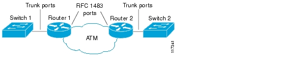
RFC 1483, Multiprotocol Encapsulation over ATM Adaptation Layer 5, specifies the implementation of point-to-point bridging of Layer 2 protocol data units (PDUs) from an ATM interface. Figure 8-1 shows an example in which the two routers receive VLANs over their respective trunk links and then forward that traffic out through the ATM interfaces into the ATM cloud.
Figure 8-1 Example of RFC 1483 Bridging Topology
Note
RFC 1483 Bridging for PVCs Configuration Guidelines
When configuring RFC 1483 bridging for PVCs, consider the following guidelines:
•
•
•
•
RFC 1483 Bridging for PVCs Configuration Task
To configure RFC 1483 bridging for PVCs, perform the following procedure beginning in global configuration mode:
Step 1
Router(config)# interface atm slot/subslot/port.subinterface point-to-point
(Optional) Creates the specified point-to-point subinterface on the given port on the specified ATM SPA, and enters subinterface configuration mode.
Note
Step 2
Router(config-subif)# pvc [name] vpi/vci [ilmi | qsaal]
Configures a new ATM PVC by assigning its VPI/VCI numbers and enters ATM VC configuration mode. The valid values for vpi/vci are:
•
•
You can also configure the following options:
•
•
•
Step 3
Router(config-if-atm-vc)# bridge-domain vlan-id [access | dot1q tag | dot1q-tunnel] [ignore-bpdu-pid] | {pvst-tlv CE-vlan} [increment] [split-horizon]
Binds the PVC to the specified vlan-id. You can optionally specify the following keywords:
•
•
•
•
•
Step 4
Router(config-if-atm-vc)# encapsulation aal5snap
(Optional) Configures the ATM adaptation layer (AAL) and encapsulation type. The default and only supported type is aal5snap.
Note
Step 5
Router(config-if-atm-vc)# end
Exits ATM VC configuration mode and returns to privileged EXEC mode.
Verifying the RFC 1483 Bridging Configuration
To verify the RFC 1483 bridging configuration and status, use the show interface atm command:
Router# show interface atm 6/1/0.3ATM6/1/0.3 is up, line protocol is upHardware is SPA-4XOC3-ATMInternet address is 10.10.10.13/24MTU 4470 bytes, BW 149760 Kbit, DLY 80 usec,reliability 255/255, txload 1/255, rxload 1/255Encapsulation ATM5 packets input, 566 bytes5 packets output, 566 bytes1445 OAM cells input, 1446 OAM cells outputConfiguring Layer 2 Protocol Tunneling Topology
To enable BPDU translation for the Layer 2 Protocol Tunneling (L2PT) topologies, use the following command line:
bridge-domain PE vlan dot1q-tunnel ignore-bpdu-pid pvst-tlv CE vlan
Configuring RFC 1483 Bridging for PVCs with IEEE 802.1Q Tunneling
RFC 1483 bridging (see the "Configuring RFC 1483 Bridging for PVCs" section) can also include IEEE 802.1Q tunneling, which allows service providers to aggregate multiple VLANs over a single VLAN, while still keeping the individual VLANs segregated and preserving the VLAN IDs for each customer. This tunneling simplifies traffic management for the service provider, while keeping the customer networks secure.
Also, the IEEE 802.1Q tunneling is configured only on the service provider routers, so it does not require any additional configuration on the customer-side routers. The customer side is not aware of the configuration.
Note
http://www.cisco.com/en/US/products/hw/routers/ps368/products_configuration_guide_chapter09186a0080160eba.html
Note
RFC 1483 Bridging for PVCs with IEEE 802.1Q Tunneling Configuration Guidelines
When configuring RFC 1483 bridging for PVCs with IEEE 802.1Q tunneling, consider the following guidelines:
•
•
•
•
•
RFC 1483 Bridging for PVCs with IEEE 802.1Q Tunneling Configuration Task
To configure RFC 1483 bridging for PVCs with IEEE 802.1Q tunneling, perform the following procedure beginning in global configuration mode:
Step 1
Router(config)# interface atm slot/subslot/port.subinterface point-to-point
(Optional) Creates the specified point-to-point subinterface on the given port on the specified ATM SPA, and enters subinterface configuration mode.
Note
Step 2
Router(config-subif)# pvc [name] vpi/vci [ilmi | qsaal]
Configures a new ATM PVC by assigning its VPI/VCI numbers and enters ATM VC configuration mode. The valid values for vpi/vci are:
•
•
You can also configure the following options:
•
•
•
Note
Step 3
Router(config-if-atm-vc)# bridge-domain vlan-id dot1q-tunnel
Binds the PVC to the specified vlan-id and enables the use of IEEE 802.1Q tunneling on the PVC. This preserves the VLAN ID information across the ATM cloud.
Step 4
Router(config-if-atm-vc)# encapsulation aal5snap
(Optional) Configures the ATM adaptation layer (AAL) and encapsulation type. The default and only supported type is aal5snap.
Note
Step 5
Router(config-if-atm-vc)# end
Exits ATM VC configuration mode and returns to privileged EXEC mode.
Verifying the RFC 1483 for PVCs Bridging with IEEE 802.1Q Tunneling Configuration
To verify the IEEE 802.1Q tunneling on an ATM SPA, use the show 12-protocol-tunnel command:
Router# show l2protocol-tunnelCOS for Encapsulated Packets: 5Port Protocol Shutdown Drop Encapsulation Decapsulation DropThreshold Threshold Counter Counter Counter------- -------- --------- --------- ------------- ------------- -------------Gi4/2 cdp ---- ---- 0 0 0stp ---- ---- 0 0 0vtp ---- ---- 0 0 0ATM6/2/1 cdp ---- ---- n/a n/a n/astp ---- ---- n/a n/a n/avtp ---- ---- n/a n/a n/a
Note
Use the following command to display the interfaces that are configured with an IEEE 802.1Q tunnel:
Router# show dot1q-tunnelLAN Port(s)-----------Gi4/2ATM Port(s)-----------ATM6/2/1Configuring ATM RFC 1483 Half-Bridging
The ATM SPA supports ATM RFC 1483 half-bridging, which routes IP traffic from a stub-bridged Ethernet LAN over a bridged RFC 1483 ATM interface, without using integrated routing and bridging (IRB). This allows bridged traffic that terminates on an ATM PVC to be routed on the basis of the destination IP address.
For example, Figure 8-2 shows a remote bridged Ethernet network connecting to a routed network over a device that bridges the Ethernet LAN to the ATM interface.
Figure 8-2 ATM RFC 1483 Half-Bridging
When half-bridging is configured, the ATM interface receives the bridged IP packets and routes them according to each packet's IP destination address. Similarly, when packets are routed to this ATM PVC, it then forwards them out as bridged packets on its bridge connection.
This use of a stub network topology offers better performance and flexibility over integrated routing and bridging (IRB). This also helps to avoid a number of issues such as broadcast storms and security risks.
In particular, half-bridging reduces the potential security risks that are associated with normal bridging configurations. Because the ATM interface allocates a single virtual circuit (VC) to a subnet (which could be as small as a single IP address), half-bridging limits the size of the nonsecured network that can be allowed access to the larger routed network. This makes half-bridging configurations ideally suited for customer access points, such digital subscriber lines (DSL).
Note
To configure a point-to-multipoint ATM PVC for ATM half-bridging, use the configuration task in the following section.
Note
ATM RFC 1483 Half-Bridging Configuration Guidelines
When configuring ATM RFC 1483 half-bridging, consider the following guidelines:
•
•
•
•
•
ATM RFC 1483 Half-Bridging Configuration Task
To configure ATM RFC 1483 half-bridging, perform the following procedure beginning in global configuration mode:
Verifying the ATM RFC 1483 Half-Bridging Configuration
To verify the ATM RFC 1483 half-bridging configuration, use the show atm vc command:
Router# show atm vc 20ATM4/0/0.20: VCD: 20, VPI: 1, VCI: 20UBR, PeakRate: 149760AAL5-LLC/SNAP, etype:0x0, Flags: 0xC20, VCmode: 0x0OAM frequency: 0 second(s)InARP frequency: 15 minutes(s), 1483-half-bridged-encapTransmit priority 6InPkts: 2411, OutPkts: 2347, InBytes: 2242808, OutBytes: 1215746InPRoc: 226, OutPRoc: 0InFast: 0, OutFast: 0, InAS: 2185, OutAS: 2347InPktDrops: 1, OutPktDrops: 0InByteDrops: 0, OutByteDrops: 0CrcErrors: 139, SarTimeOuts: 0, OverSizedSDUs: 0, LengthViolation: 0, CPIErrors: 0Out CLP=1 Pkts: 0OAM cells received: 0OAM cells sent: 0Status: UPConfiguring ATM Routed Bridge Encapsulation
The ATM SPAs support ATM Routed Bridge Encapsulation (RBE), which is similar in functionality to RFC 1483 ATM half-bridging, except that ATM half-bridging is configured on a point-to-multipoint PVC, while RBE is configured on a point-to-point PVC (see the "Configuring ATM RFC 1483 Half-Bridging" section).
Note
Use the following configuration task to configure a point-to-point subinterface and PVC for RBE bridging.
Note
ATM Routed Bridge Encapsulation Configuration Guidelines
When configuring ATM RBE, consider the following guidelines:
•
•
•
•
•
•
•
•
•
RBE Configuration Limitation Supports Only One Remote MAC Address
On the Cisco 7600 series router with a Supervisor Engine 720 or Route Switch Processor 720 (RSP720) and the following SPA, an ATM PVC with an RBE configuration can send packets to only a single MAC address:
•
This restriction occurs because the Cisco 7600 series router keeps only one MAC address attached to an RBE PVC. The MAC address-to-PVC mapping is refreshed when a packet is received from the host. If there are multiple hosts connected to the PVC, the mapping is not stable and traffic forwarding is affected.
The solution to this problem is as follows:
1.
2.
ATM Routed Bridge Encapsulation Configuration Task
To configure ATM routed bridge encapsulation, perform the following procedure beginning in global configuration mode:
Note
Verifying the ATM Routed Bridge Encapsulation Configuration
To verify the RBE bridging configuration, use the show ip cache verbose command:
Router# show ip cache verboseIP routing cache 3 entries, 572 bytes9 adds, 6 invalidates, 0 refcountsMinimum invalidation interval 2 seconds, maximum interval 5 seconds,quiet interval 3 seconds, threshold 0 requestsInvalidation rate 0 in last second, 0 in last 3 secondsLast full cache invalidation occurred 00:30:34 agoPrefix/Length Age Interface Next Hop10.1.0.51/32-24 00:30:10 Ethernet3/1/0 10.1.0.51 14 0001C9F2A81D00600939BB55080010.8.100.50/32-24 00:00:04 ATM1/1/0.2 10.8.100.50 28 00010000AA030080C2000700000007144F5D201C080010.8.101.35/32-24 00:06:09 ATM1/1/0.4 10.8.101.35 28 00020000AA030080C20007000000E01E8D3F901C0800Configuring RFC 1483 Bridging of Routed Encapsulations
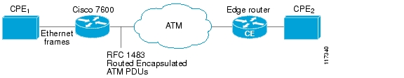
Bridging of routed encapsulations (BRE) enables the ATM SPA to receive RFC 1483 routed encapsulated packets and forward them as Layer 2 frames. In a BRE configuration, the PVC receives the routed PDUs, removes the RFC 1483 routed encapsulation header, and adds an Ethernet MAC header to the packet. The Layer 2 encapsulated packet is then switched by the forwarding engine to the Layer 2 interface determined by the VLAN number and destination MAC.
Note
Figure 8-3 shows a topology where an interface on an ATM SPA receives routed PDUs from the ATM cloud and encapsulates them as Layer 2 frames. It then forwards the frames to the Layer 2 customer device.
Figure 8-3 Example BRE Topology
RFC 1483 Bridging of Routed Encapsulations Configuration Guidelines
When configuring RFC 1483 bridging of routed encapsulations, consider the following guidelines:
•
•
•
•
•
•
•
•
RFC 1483 Bridging of Routed Encapsulations Configuration Task
To configure RFC 1483 bridging of routed encapsulations, perform the following procedure beginning in global configuration mode:
Step 1
Router(config)# interface atm slot/subslot/port
Enters interface configuration mode for the indicated port on the specified ATM SPA.
Step 2
Router(config-if)# no ip address
Assigns no IP address to the interface.
Step 3
Router(config-if)# spanning-tree bpdufilter enable
(Optional) Blocks all Spanning Tree BPDUs on the ATM interface. This command should be used if this ATM interface is configured only for BRE VLANs.
Note
Step 4
Router(config-if)# no shutdown
Enables the interface.
Step 5
Router(config-if)# interface atm slot/subslot/port.subinterface point-to-point
Creates the specified point-to-point subinterface on the given port on the specified ATM SPA, and enters subinterface configuration mode.
Step 6
Router(config-subif)# no ip address
Assigns no IP address to the subinterface.
Step 7
Router(config-subif)# pvc [name] vpi/vci [ilmi | qsaal]
Configures a new ATM PVC by assigning its VPI/VCI numbers and enters ATM VC configuration mode. The valid values for vpi/vci are:
•
•
You can also configure the following options:
•
•
•
Note
Step 8
Router(config-if-atm-vc)# bre-connect vlan-id [mac mac-address]
Enables BRE bridging on the PVC, where:
•
Step 9
Router(config-if-atm-vc)# interface gigabitethernet slot/port
Enters interface configuration mode for the specified Gigabit Ethernet interface.
Step 10
Router(config-if)# switchport
Configures the Gigabit Ethernet interface for Layer 2 switching.
Step 11
Router(config-if)# switchport access vlan vlan-id
(Optional) Specifies the default VLAN for the interface. This should be the same VLAN ID that was specified in the bre-connect command in Step 8.
Step 12
Router(config-if)# switchport mode access
Puts the interface into nontrunking mode.
Step 13
Router(config-if)# end
Exits interface configuration mode and returns to privileged EXEC mode.
Verifying the RFC 1483 Bridging of Routed Encapsulations Configuration
Use the following commands to verify the RFC 1483 bridging of routed encapsulations configuration:
Router# show running-config interface atm10/0/3.111 Building configuration...Current configuration : 149 bytes!interface ATM10/0/3.111 point-to-point no atm enable-ilmi-trap nosnmp trap link-status pvc 11/101bre-connect 11 mac 0100.1234.1234Router# show running-config interface gigabitethernet 1/2interface GigabitEthernet1/2no ip addressswitchportswitchport access vlan 100no cdp enable!Router# show vlan id 100VLAN Name Status Ports---- -------------------------------- --------- -------------------------------100 VLAN0100 active Gi1/2, AT5/0/2VLAN Type SAID MTU Parent RingNo BridgeNo Stp BrdgMode Trans1 Trans2---- ----- ---------- ----- ------ ------ -------- ---- -------- ------ ------100 enet 100100 1500 - - - - - 0 0Router# show atm vlanInterface Bridge VCD Vlan IDATM4/5/0/2.1 1 100Configuring MPLS over RBE
The ATM SPAs support MLPS over RBE on a Cisco 7600 SIP-200. For more information on routed bridged encapsulation (RBE), see the "Configuring ATM Routed Bridge Encapsulation" section. To use this feature, configure both RBE and MPLS on the ATM subinterface using the following procedure:
Verifying MPLS over RBE Configuration
Use the following commands to verify MPLS over RBE configuration:
Router# show running interfaces a4/1/0.200interface ATM4/1/0.200 point-to-pointip address 3.0.0.2 255.255.0.0atm route-bridged iptag-switching ippvc 10/200!Router# show mpls interfacesInterface IP Tunnel OperationalATM4/1/0.200 Yes (ldp) No YesRouter# show mpls ldp bindingstib entry: 5.0.0.0/16, rev 2local binding: tag: imp-nulltib entry: 6.0.0.0/16, rev 4local binding: tag: imp-nullremote binding: tsr: 3.0.0.1:0, tag: imp-nullRouter# show mpls ldp neighborPeer LDP Ident: 3.0.0.1:0; Local LDP Ident 3.0.0.2:0TCP connection: 3.0.0.1.646 - 3.0.0.2.11001State: Oper; Msgs sent/rcvd: 134/131; DownstreamUp time: 01:51:08LDP discovery sources:ATM4/1/0.200, Src IP addr: 6.0.0.1Addresses bound to peer LDP Ident:6.0.0.1Router# show mpls forwardingLocal Outgoing Prefix Bytes tag Outgoing Next Hoptag tag or VC or Tunnel Id switched interface16 Pop tag 3.0.0.0/16 0 AT4/1/0.200 6.0.0.117 Pop tag 16.16.16.16/32 0 AT4/1/0.200 6.0.0.118 19 13.13.13.13/32 134 AT4/1/0.200 6.0.0.1 <<<<<19 Pop tag 17.17.17.17/32 0 PO8/0/0.1 point2pointConfiguring Aggregate WRED for PVCs
Weighted Random Early Detection (WRED) is the Cisco implementation of Random Early Detection (RED) for standard Cisco IOS platforms. RED is a congestion-avoidance technique that takes advantage of the congestion-control mechanism of TCP to anticipate and avoid congestion before it occurs. By dropping packets prior to periods of high congestion, RED tells the packet source (usually TCP) to decrease its transmission rate. When configured, WRED can selectively discard lower priority traffic and provide differentiated performance characteristics for different classes of service.
The Aggregate WRED feature provides a means to overcome limitations of WRED implementations that can only support a limited number of unique subclasses. When an interface enables support for aggregate WRED, subclasses that share the same minimum threshold, maximum threshold, and mark probability values can be configured into one aggregate subclass based on their IP precedence value or differentiated services code point (DSCP) value. (The DSCP value is the first six bits of the IP type of service [ToS] byte.) You can also define a default aggregate subclass for all subclasses that have not been explicitly defined.
For more complete information on WRED, refer to the Cisco IOS Quality of Service Solutions Configuration Guide.
Aggregate WRED Configuration Guidelines
When configuring aggregate WRED on an ATM SPA interface, consider the following guidelines:
•
•
•
•
•
•
•
•
Configuring Aggregate WRED Based on IP Precedence
To configure aggregate WRED to drop packets based on IP precedence values, use the following commands beginning in global configuration mode:
Verifying the Precedence-Based Aggregate WRED Configuration
To verify a precedence-based aggregate WRED configuration, use the show policy-map interface command. Note that the statistics for IP precedence values 0 through 3 and 4 and 5 have been aggregated into one line each.
Router# show policy-map interface a4/1/0.10ATM4/1/0.10: VC 10/110 -Service-policy output: prec-aggr-wredClass-map: class-default (match-any)0 packets, 0 bytes5 minute offered rate 0 bps, drop rate 0 bpsMatch: anyExp-weight-constant: 9 (1/512)Mean queue depth: 0class Transmitted Random drop Tail drop Minimum Maximum Markpkts/bytes pkts/bytes pkts/bytes thresh thresh prob0 1 2 3 0/0 0/0 0/0 10 100 1/104 5 0/0 0/0 0/0 40 400 1/106 0/0 0/0 0/0 60 600 1/107 0/0 0/0 0/0 70 700 1/10Configuring Aggregate WRED Based on DSCP
To configure aggregate WRED to drop packets based on the differentiated services code point (DSCP) value, use the following commands beginning in global configuration mode:
Verifying the DSCP-Based Aggregate WRED Configuration
To verify a DSCP-based aggregate WRED configuration, use the show policy-map interface command. Note that the statistics for DSCP values 0 through 3, 4 through 7, and 8 through 11 have been aggregated into one line each.
Router# show policy-map interface a4/1/0.11ATM4/1/0.11: VC 11/101 -Service-policy output: dscp-aggr-wredClass-map: class-default (match-any)0 packets, 0 bytes5 minute offered rate 0 bps, drop rate 0 bpsMatch: anyExp-weight-constant: 0 (1/1)Mean queue depth: 0class Transmitted Random drop Tail drop Minimum Maximum Markpkts/bytes pkts/bytes pkts/bytes thresh thresh probdefault 0/0 0/0 0/0 1 10 1/100 1 2 34 5 6 7 0/0 0/0 0/0 10 20 1/108 9 10 11 0/0 0/0 0/0 10 40 1/10Creating and Configuring Switched Virtual Circuits
A switched virtual circuit (SVC) is created and released dynamically, providing user bandwidth on demand. To enable the use of SVCs, you must configure a signaling protocol to be used between the Cisco 7600 series router and the ATM switch. The ATM SPA supports versions 3.0, 3.1, and 4.0 of the User-Network Interface (UNI) signaling protocol, which uses the Integrated Local Management Interface (ILMI) to establish, maintain, and clear the ATM connections at the UNI.
The Cisco 7600 series router does not perform ATM-level call routing when configured for UNI/ILMI operation. Instead, the ATM switch acts as the network and performs the call routing, while the Cisco 7600 series router acts only as the user end-point of the call circuit and only routes packets through the resulting circuit.
Note
To use UNI/ILMI signaling, you must create an ILMI PVC and a signaling PVC to be used for the SVC call-establishment and call-termination messages between the ATM switch and Cisco 7600 series router. This also requires configuring the ATM interface with a network service access point (NSAP) address that uniquely identifies itself across the network.
The NSAP address consists of a network prefix (13 hexadecimal digits), a unique end station identifier (ESI) of 6 hexadecimal bytes, and a selector byte. If an ILMI PVC exists, the Cisco 7600 series router can obtain the NSAP prefix from the ATM switch, and you must manually configure only the ESI and selector byte. If an ILMI PVC does not exist, or if the ATM switch does not support this feature, you must configure the entire address manually.
To create and configure an SVC, use the following procedure beginning in global configuration mode:
Step 1
Router(config)# interface atm slot/subslot/port
Enters interface configuration mode for the indicated port on the specified ATM SPA.
Step 2
Router(config-subif)# pvc [name] 0/5 qsaal
Configures a new ATM PVC to be used for SVC signaling:
•
•
•
Note
•
Step 3
Router(config-subif)# pvc [name] 0/16 ilmi
Creates a new ATM PVC to be used for ILMI signaling:
•
•
•
•
Note
Step 4
Router(config-if-atm-vc)# exit
Exits ATM PVC configuration mode and returns to interface configuration mode.
Step 5
Router(config-if)# atm ilmi-keepalive [seconds] [retry counts]
(Optional) Enables ILMI keepalive messages and sets the interval between them. ILMI keepalive messages are disabled by default.
•
•
Step 6
Router(config-if)# atm esi-address esi.selector
Specifies the end station ID (ESI) and selector fields for the local portion of the interface's NSAP address, and configures the interface to get the NSAP prefix from the ATM switch.
•
•
To configure the ATM address, you need to enter only the ESI (12 hexadecimal digits) and the selector byte (2 hexadecimal digits). The NSAP prefix (26 hexadecimal digits) is provided by the ATM switch.
or
Router(config-if)# atm nsap-address nsap-address
Assigns a complete NSAP address (40 hexadecimal digits) to the interface. The address consists of a network prefix, ESI, and selector byte, and must be in the following format:
XX.XXXX.XX.XXXXXX.XXXX.XXXX.XXXX.XXXX.XXXX.XXXX.XXNote
Note
Step 7
Router(config-if)# interface atm slot/subslot/port.subinterface [multipoint | point-to-point]
(Optional) Creates the specified subinterface on the specified ATM interface, and enters subinterface configuration mode.
Note
Step 8
Router(config-subif)# svc [name] nsap address
Creates an SVC and specifies the destination NSAP address (40 hexadecimal digits in dotted notation). You can also configure the following option:
•
Step 9
Router(config-if-atm-vc)# oam-svc [manage] [frequency]
Enables end-to-end Operation, Administration, and Maintenance (OAM) loopback cell generation and management of the SVC.
•
•
Step 10
Router(config-if-atm-vc)# protocol protocol {protocol-address | inarp} [[no] broadcast]
Configures the SVC for a particular protocol and maps it to a specific protocol-address.
•
•
•
•
Step 11
Router(config-if-atm-vc)# encapsulation aal5snap
(Optional) Configures the ATM adaptation layer (AAL) and encapsulation type. The default and only supported type is aal5snap.
Note
Step 12
Router(config-if-atm-vc)# end
Exits SVC configuration mode and returns to privileged EXEC mode.
Verifying the SVC Configuration
Use the show atm svc and show atm ilmi-status commands to verify the configuration of the SVCs that are currently configured on the Cisco 7600 series router.
Router# show atm svcVCD / Peak Avg/Min BurstInterface Name VPI VCI Type Encaps SC Kbps Kbps Cells Sts4/0/0 1 0 5 SVC SAAL UBR 155000 UP4/0/2 4 0 35 SVC SNAP UBR 155000 UP4/1/0 16 0 47 SVC SNAP UBR 155000 UP4/1/0.1 593 0 80 SVC SNAP UBR 155000 UP
Tip
To display detailed information about a particular SVC, specify its VPI and VCI values:
Router# show atm svc 0/35ATM5/1/0.200: VCD: 3384, VPI: 0, VCI: 35, Connection Name: SVC00UBR, PeakRate: 155000AAL5-MUX, etype:0x800, Flags: 0x44, VCmode: 0x0OAM frequency: 10 second(s), OAM retry frequency: 1 second(s)OAM up retry count: 3, OAM down retry count: 5OAM Loopback status: OAM ReceivedOAM VC status: VerifiedILMI VC status: Not ManagedVC is managed by OAM.InARP DISABLEDTransmit priority 6InPkts: 0, OutPkts: 4, InBytes: 0, OutBytes: 400InPRoc: 0, OutPRoc: 4, Broadcasts: 0InFast: 0, OutFast: 0, InAS: 0, OutAS: 0InPktDrops: 0, OutPktDrops: 0CrcErrors: 0, SarTimeOuts: 0, OverSizedSDUs: 0, LengthViolation: 0, CPIErrors: 0Out CLP=1 Pkts: 0OAM cells received: 10F5 InEndloop: 10, F5 InSegloop: 0, F5 InAIS: 0, F5 InRDI: 0F4 InEndloop: 0, F4 InSegloop: 0, F4 InAIS: 0, F4 InRDI: 0OAM cells sent: 10F5 OutEndloop: 10, F5 OutSegloop: 0, F5 OutRDI: 0F4 OutEndloop: 0, F4 OutSegloop: 0, F4 OutRDI: 0OAM cell drops: 0Status: UPTTL: 4interface = ATM5/1/0.200, call locally initiated, call reference = 8094273vcnum = 3384, vpi = 0, vci = 35, state = Active(U10), point-to-point callRetry count: Current = 0timer currently inactive, timer value = 00:00:00Remote Atm Nsap address: 47.00918100000000107B2B4B01.111155550001.00, VC owner: ATM_OWNER_SMAPTo display information about the ILMI status and NSAP addresses being used for the SVCs on an ATM interface, use the show atm ilmi-status command:
Router# show atm ilmi-status atm 4/1/0Interface : ATM4/1/0 Interface Type : Private UNI (User-side)ILMI VCC : (0, 16) ILMI Keepalive : Enabled/Up (5 Sec 4 Retries)ILMI State: UpAndNormalPeer IP Addr: 10.10.13.1 Peer IF Name: ATM 3/0/3Peer MaxVPIbits: 8 Peer MaxVCIbits: 14Active Prefix(s) :47.0091.8100.0000.0010.11b8.c601End-System Registered Address(s) :47.0091.8100.0000.0010.11b8.c601.2222.2222.2222.22(Confirmed)47.0091.8100.0000.0010.11b8.c601.aaaa.aaaa.aaaa.aa(Confirmed)
Tip
Configuring Traffic Parameters for PVCs or SVCs
After creating a PVC or SVC, you can also configure it for the type of traffic quality of service (QoS) class to be used over the circuit:
•
•
•
Note
•
•
Each service class is assigned a different transmit priority, which the Cisco 7600 series router uses to determine which queued cell is chosen to be transmitted out of an interface during any particular cell time slot. This ensures that real-time QoS classes have a higher likelihood of being transmitted during periods of congestion. Table 8-1 lists the ATM QoS classes and their default transmit priorities.
Table 8-1 ATM Classes of Service and Default Transmit Priorities
Signaling, Operation, Administration, and Maintenance (OAM) cells, and other control cells
0 (highest)
CBR when greater than 5 percent of the line rate
1
CBR when less than 5 percent of the line rate
2
Voice traffic
3
VBR-rt
4
VBR-nrt
5
UBR
6
Unused and not available or configurable
7 (lowest)
1 The default priorities can be changed for individual VCs using the transmit-priority VC configuration command.
Note
You can configure a PVC or SVC for only one QoS service class. If you enter more than one type, only the most recently configured QoS class takes effect on the circuit.
To configure the traffic parameters for a PVC or SVC, perform the following procedure beginning in global configuration mode:
Step 1
Router(config)# interface atm slot/subslot
or
Router(config)# interface atm slot/subslot/port.subinterface [multipoint | point-to-point]Enters interface or subinterface configuration mode for the indicated port on the specified ATM SPA.
Step 2
Router(config-if)# pvc [name] vpi/vci
or
Router(config-if)# svc [name] nsap-addressSpecifies the PVC or SVC to be configured, and enters PVC/SVC configuration mode.
Note
Step 3
Router(config-if-atm-vc)# cbr rate
Configures constant bit rate (CBR) quality of service (QoS) and average cell rate for the PVC or SVC:
•
or
Router(config-if-atm-vc)# ubr output-pcr [input-pcr]
Configures unspecified bit rate (UBR) quality of service (QoS) and peak cell rate (PCR) for the PVC or SVC:
•
•
or
Router(config-if-atm-vc)# vbr-nrt output-pcr output-scr output-mbs [input-pcr] [input-scr] [input-mbs]
Configures the variable bit rate-nonreal time (VBR-nrt) QoS, the peak cell rate (PCR), sustainable cell rate (SCR), and maximum burst cell size (MBS) for the PVC or SVC:
•
•
•
•
•
•
or
Router(config-if-atm-vc)# vbr-rt pcr scr burst
Configures the variable bit rate-real time (VBR-rt) QoS, and the PCR, average cell rate (ACR), and burst cell size (BCS) for the PVC or SVC:
•
•
•
Step 4
Router(config-if-atm-vc)# transmit-priority level
(Optional) Configures the PVC for a new transmit priority level.
•
Note
Step 5
Router(config-if-atm-vc)# end
Exits PVC/SVC configuration mode and returns to privileged EXEC mode.
Verifying the Traffic Parameter Configuration
Use the show atm vc command to verify the configuration of the traffic parameters for a PVC or SVC:
Router# show atm vc 20ATM1/1/0.200: VCD: 20, VPI: 2, VCI: 200UBR, PeakRate: 44209AAL5-LLC/SNAP, etype:0x0, Flags: 0xC20, VCmode: 0x0OAM frequency: 0 second(s)InARP frequency: 5 minutes(s)Transmit priority 4InPkts: 10, OutPkts: 11, InBytes: 680, OutBytes: 708InPRoc: 10, OutPRoc: 5, Broadcasts: 0InFast: 0, OutFast: 0, InAS: 0, OutAS: 6InPktDrops: 0, OutPktDrops: 0CrcErrors: 0, SarTimeOuts: 0, OverSizedSDUs: 0OAM cells received: 0OAM cells sent: 0Status: UPTo verify the configuration of all PVCs or SVCs on an interface, use the show atm vc interface atm command:
Router# show atm vc interface atm 2/1/0ATM2/1/0.101: VCD: 201, VPI: 20, VCI: 101UBR, PeakRate: 149760AAL5-LLC/SNAP, etype:0x0, Flags: 0xC20, VCmode: 0x0OAM frequency: 0 second(s)InARP frequency: 15 minutes(s)Transmit priority 4InPkts: 3153520, OutPkts: 277787, InBytes: 402748610, OutBytes: 191349235InPRoc: 0, OutPRoc: 0, Broadcasts: 0InFast: 211151, OutFast: 0, InAS: 0, OutAS: 0InPktDrops: 0, OutPktDrops: 17CrcErrors: 0, SarTimeOuts: 0, OverSizedSDUs: 0OAM cells received: 0OAM cells sent: 0Status: UPConfiguring Virtual Circuit Classes
When multiple PVCs or SVCs use the same or similar configurations, you can simplify the Cisco 7600 series router's configuration file by creating virtual circuit (VC) classes. Each VC class acts as a template, which you can apply to an ATM interface or subinterface, or to individual PVCs or SVCs.
When you apply a VC class to an ATM interface or subinterface, all PVCs and SVCs created on that interface or subinterface inherit the VC class configuration. When you apply a VC class to an individual PVC or SVC, that particular PVC or SVC inherits the class configuration.
You can then customize individual PVCs and SVCs with further configuration commands. Any commands that you apply to individual PVCs and SVCs take precedence over those of the VC class that were applied to the interface or to the PVC/SVC.
To create and configure a VC class, and then apply it to an interface, subinterface, or individual PVC or SVC, use the following procedure beginning in global configuration mode:
Step 1
Router(config)# vc-class atm vc-class-name
Creates an ATM virtual circuit (VC) class and enters VC-class configuration mode.
•
Step 2
Router(config-vc-class)# configuration-commands
Enter any PVC or SVC configuration commands for this VC class. See the "Creating a Permanent Virtual Circuit" section and the "Creating and Configuring Switched Virtual Circuits" section for additional information.
Note
Step 3
Router(config-vc-class)# interface atm slot/subslot/port
or
Router(config-vc-class)# interface atm slot/subslot/port.subinterface [multipoint | point-to-point]Enters subinterface configuration mode for the specified ATM interface or subinterface.
Step 4
Router(config-if)# class-int vc-class-name
(Optional) Applies a VC class on the ATM main interface or subinterface. This class then applies to all PVCs or SVCs that are created on that interface.
•
Step 5
Router(config-if)# pvc [name] vpi/vci
or
Router(config-if)# svc [name] nsap-addressSpecifies the PVC or SVC to be configured, and enters ATM VC configuration mode.
Note
Step 6
Router(config-if-atm-vc)# class-vc vc-class-name
Assigns the specified VC class to this PVC or SVC.
•
Step 7
Router(config-if-atm-vc)# configuration-commands
Any other VC configuration commands to be applied to this particular PVC or SVC. Commands that are applied to the individual PVC or SVC supersede any conflicting commands that were specified in the VC class.
Step 8
Router(config-if)# end
Exits interface configuration mode and returns to privileged EXEC mode.
Verifying the Virtual Circuit Class Configuration
To verify the virtual circuit class configuration, use the show atm vc command:
Router# show atm vcVCD / Peak Avg/Min BurstInterface Name VPI VCI Type Encaps SC Kbps Kbps Cells Sts6/1/0 1 0 5 PVC SAAL UBR 155000 UP6/1/0 2 0 16 PVC ILMI UBR 155000 UP6/1/0.1 3 1 32 PVC-D SNAP UBR 155000 UP6/1/0.2 4 2 32 PVC-D SNAP UBR 155000 UPConfiguring Virtual Circuit Bundles
Virtual circuit bundles are similar to VC classes, in that they allow you to configure a large group of PVCs by configuring a template (the VC bundle). The main difference between a VC bundle and a VC class is that the VC bundle management allows you to configure multiple VCs that have different QoS characteristics between any pair of ATM-connected routers.
Using VC bundles, you first create an ATM VC bundle and then add VCs to it, and each VC in the bundle can have its own ATM traffic class and ATM traffic parameters. You can configure the VCs collectively at the bundle level, or you can configure the individual VC bundle members. You can also apply a VC class to a bundle to apply the VC class configuration to all of the VCs in the bundle.
You can therefore create differentiated service by mapping one or more MPLS EXP levels to each VC in the bundle, thereby enabling individual VCs in the bundle to carry packets marked with different MPLS EXP levels. The ATM VC bundle manager determines which VC to use for a particular packet by matching the MPLS EXP level of the packet to the MPLS EXP levels assigned to the VCs in the bundle. The bundle manager can also use Weighted Random Early Detection (WRED) or distributed WRED (dWRED) to further differentiate service across traffic that has different MPLS EXP levels.
Virtual Circuit Bundles Configuration Guidelines
•
•
•
•
Virtual Circuit Bundles Configuration Task
To create and configure a VC bundle and then apply it to an ATM interface or subinterface, perform the following procedure beginning in global configuration mode:
Step 1
Router(config)# ip cef [distributed]
Enables Cisco Express Forwarding (CEF) Layer 3 switching on the Cisco 7600 series router. The Cisco 7600 series router enables CEF by default.
•
Step 2
Router(config)# mpls label protocol ldp
Specifies the default label distribution protocol for a platform.
Step 3
Router(config)# interface atm slot/subslot/port
or
Router(config)# interface atm slot/subslot/port.subinterface [multipoint | point-to-point]Enters interface configuration mode for the specified ATM interface or subinterface.
Step 4
Router(config-if)# mpls ip
Enables MPLS forwarding of IPv4 packets along normally routed paths for the interface.
Step 5
Router(config-if)# bundle bundle-name
Creates an ATM virtual circuit (VC) bundle and enters bundle configuration mode.
•
Step 6
Router(config-if-atm-bundle)# class-bundle vc-class-name
(Optional) Applies a VC class to this bundle. The class configuration is then applied to all VCs in the bundle.
•
Step 7
Router(config-if-atm-bundle)# configuration-commands
Enter any other PVC or SVC configuration commands for this VC bundle. See the "Creating a Permanent Virtual Circuit" section and the "Creating and Configuring Switched Virtual Circuits" section for additional information.
Note
Step 8
Router(config-if-atm-bundle)# pvc-bundle [name] vpi/vci
Creates a member PVC of the bundle and enters PVC bundle configuration mode.
Step 9
Router(config-if-atm-member)# mpls experimental [level | other | range]
(Optional) Configures the MPLS EXP levels for the PVC bundle member.
•
•
•
Step 10
Router(config-if-atm-member)# bump {implicit | explicit precedence-level | traffic}
(Optional) Configures the bumping rules for the PVC bundle member.
•
•
•
Step 11
Router(config-if-atm-member)# protect {group | vc}
(Optional) Specifies that the PVC bundle member is protected.
•
•
By default, PVC bundle members are not protected.
Step 12
Router(config-if-atm-member)# configuration-commands
Any other VC configuration commands to be applied to this particular VC bundle member. Commands that are applied to a bundle member supersede any conflicting commands that were specified in the VC class or VC bundle.
Note
Step 13
Router(config-if-atm-member)# end
Exits PVC bundle configuration mode and returns to privileged EXEC mode.
Verifying the Virtual Circuit Bundles Configuration
To verify the configuration of the virtual circuit bundles and display the configuration for its interface or subinterface, use the show running-config interface atm command, as in the following example:
Router# show running-config interface atm 4/1/0.2interface ATM4/1/0.2 point-to-pointip address 10.10.10.1 255.255.255.0no ip directed-broadcastno atm enable-ilmi-trapbundle ABCclass-bundle bundle-classpvc-bundle ABC-high 1/107class-vc highpvc-bundle ABC-med 1/105class-vc medpvc-bundle ABC-low 1/102class-vc low!!To verify the operation and current status of a virtual circuit bundle, specify the bundle name with the show atm bundle command:
Router# show atm bundle ABCABC on ATM4/1/0.2: UPConfig Current Bumping PG/ Peak Avg/Min BurstVC Name VPI/ VCI Prec/Exp Prec/Exp PrecExp/ PV Kbps kbps Cells StsAcceptABC-high 1/107 7 7 - / Yes PV 10000 5000 32 UPABC-med 1/105 6 6 - / Yes PV 10000 UPABC-low 1/102 5-0 5-0 - / Yes - 10000 UPConfiguring Multi-VLAN to VC Support
For information on configuring multi-VLAN to VC support, see the "Configuring QoS for ATM VC Access Trunk Emulation" topic at http://www.cisco.rw/univercd/cc/td/doc/product/ core/cis7600/cfgnotes/flexport/combo/flexqos.htm#wp1162305.
Configuring Link Fragmentation and Interleaving with Virtual Templates
The ATM SPA supports Link Fragmentation and Interleaving (LFI) with the distributed Compressed Real-Time Protocol (dCRTP). This allows the ATM interfaces, which are cell-based, to efficiently transport packet-based IP traffic without an excessive amount of bandwidth being used for packet headers and other overhead.
The LFI/dCRTP feature requires the use of multilink PPP (MLP), which can be implemented either by using virtual templates or dialer templates.
Link Fragmentation and Interleaving with Virtual Templates Configuration Guidelines
•
•
•
•
•
•
Link Fragmentation and Interleaving with Virtual Templates Configuration Task
To configure LFI with virtual templates, perform the following procedure beginning in global configuration mode:
Verifying the Link Fragmentation and Interleaving with Virtual Templates Configuration
To verify a virtual template configuration, display the running configuration for the configured ATM and virtual interfaces:
Router# show running-config interface virtual-template 1!interface Virtual-Template1Current configuration : 373 bytes!interface Virtual-Template1bandwidth 300ip address 23.0.0.1 255.255.255.0ppp chap hostname template1ppp multilinkppp multilink fragment-delay 8ppp multilink interleaveservice-policy output lfiqos!Router# show running-config interface atm 6/0/1!interface ATM6/0/1atm idle-cell-format ituatm enable-payload-scramblingno atm ilmi-keepalivepvc 32/32vbr-rt 640 640 256encapsulation aal5snapprotocol ppp Virtual-Template1To display run-time statistics and other information about the currently configured multilink PPP bundles, use the show ppp multilink command:
Router# show ppp multilinkVirtual-Access3, bundle name is north-2Bundle up for 00:01:51Bundle is Distributed0 lost fragments, 0 reordered, 0 unassigned0 discarded, 0 lost received, 1/255 load0x0 received sequence, 0x0 sent sequenceMember links: 1 (max not set, min not set)Vi1, since 00:01:38, no frags rcvd, 62 weight, 54 frag sizedLFI statistics:DLFI Packets Pkts In Pkts OutFragmented 4294967288 3129990UnFragmented 1249071 0Reassembled 1249071 1564994Reassembly Drops 0Fragmentation Drops 0Out of Seq Frags 0
Note
Configuring the Distributed Compressed Real-Time Protocol
The distributed Compressed Real-Time Protocol (dCRTP) compresses the 40 bytes of the IP/UDP/RTP packet headers down to between only two and four bytes in a distributed fast-switching and distributed Cisco Express Forwarding (dCEF) network. This compression reduces the packet size, improves the speed of packet transmission, and reduces packet latency, especially on cell-based interfaces, such as ATM interfaces.
Distributed Compressed Real-Time Protocol Configuration Guidelines
When configuring dCRTP, consider the following guidelines:
•
•
Distributed Compressed Real-Time Protocol Configuration Task
To enable and configure dCRTP on an ATM interface, virtual template interface, or a dialer template interface, perform the following procedure beginning in global configuration mode:
Verifying the Distributed Compressed Real-Time Protocol Configuration
To verify the dCRTP of an ATM interface, use the show running-config interface interface virtual-template command:
Router# show running-config interface interface virtual-template 1!interface Virtual-Template1bandwidth 2320ip unnumbered Loopback2max-reserved-bandwidth 100ip tcp header-compressionppp multilinkppp multilink fragment delay 4ppp multilink interleaveip rtp header-compressionConfiguring Automatic Protection Switching
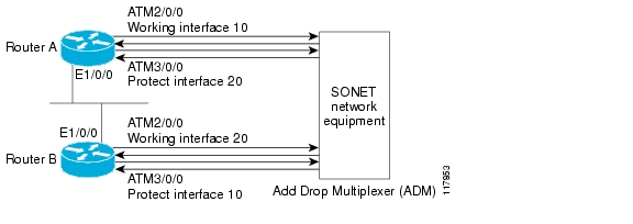
The ATM SPAs support 1+1 Automatic Protection Switching (APS) on PVCs as described in section 5.3 of the Telcordia publication GR-253-CORE SONET Transport Systems: Common Generic Criteria. APS redundancy is supported at the line layer, so that when an OC-3c, OC-12c, or OC-48c link fails, all of the PVCs that are carried by that link are switched simultaneously.
Note
In an APS configuration, a redundant ATM interface (the Protect interface) is configured for every active ATM interface (the Working interface). If the Working interface goes down, the Protect interface automatically switches over and continues communication over the interface's PVCs.
The APS Protect Group Protocol (PGP), which runs on top of User Datagram Protocol (UDP), provides communication between the Working and Protect interfaces. This communication occurs over a separate out-of-band (OOB) communication channel, such as an Ethernet link.
In the case of degradation, loss of channel signal, or manual intervention, the APS software on the Protect interface sends APS PGP commands to activate or deactivate the Working interface as necessary. If the communication channel between the Working and Protect interfaces is lost, the Working interface assumes full control, as if no Protect interface existed.
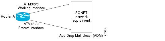
Figure 8-4 shows a very simple example of a pair of Working and Protect interfaces on a single router.
Figure 8-4 Basic Automatic Protection Switching Configuration
Tip
Multiple routers can be using APS at the same time. For example, Figure 8-5 shows a simple example of two routers that each have one pair of Working and Protect interfaces. In this configuration, the two routers are independently configured.
Figure 8-5 Sample Automatic Protection Switching Configuration with Multiple Routers
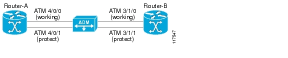
You can also configure multiple routers with APS so that interfaces on one router can provide protection for the interfaces on another router. This provides protection in case a router experiences a major system problem, such as a processor fault.
Figure 8-6 shows a basic example of two routers that each have one Working ATM interface. Each router also has one Protect interface that provides protection for the other router's Working interface. Note that this configuration requires a separate out-of-band (OOB) communication link between the two routers, which in this case is provided by the Ethernet network.
Figure 8-6 Sample Multiple Router Protection with Automatic Protection Switching
An APS configuration requires the following steps:
•
•
•
Tip
Automatic Protection Switching Configuration Guidelines
When configuring APS, consider the following guidelines:
•
•
•
•
•
•
Automatic Protection Switching Configuration Task
To configure the Working and Protect interfaces on the ATM SPAs for basic APS operation, perform the following procedure beginning in global configuration mode. For complete information on APS, including information on additional APS features, refer to the "Configuring ATM Interfaces" chapter in the Cisco IOS Interface Configuration Guide, Release 12.2.
Step 1
Router(config)# interface loopback interface-number
Creates a loopback interface and enters interface configuration mode:
•
Step 2
Router(config-if)# ip address ip-address mask [secondary]
Specifies the IP address and subnet mask for this loopback interface. If the Working and Protect interfaces are on the same router, this IP address should be in the same subnet as the Working interface. If the Working and Protect interfaces are on different routers, this IP address should be in the same subnet as the Ethernet interface that provides the connectivity between the two routers.
Repeat this command with the secondary keyword to specify additional IP addresses to be used for this interface.
Step 3
Router(config-if)# interface atm slot/subslot/port
Enters interface configuration mode for the Working interface on the ATM SPA.
Step 4
Router(config-if)# ip address ip-address mask [secondary]
Specifies the IP address and subnet mask for the Working interface.
Repeat this command with the secondary keyword to specify additional IP addresses to be used for the interface.
Step 5
Router(config-if)# aps group group-number
Enables the use of the APS Protect Group Protocol for this Working interface.
•
Note
Step 6
Router(config-if)# aps working circuit-number
Identifies the interface as the Working interface.
•
Step 7
Router(config-if)# aps authentication security-string
(Optional) Specifies a security string that must be included in every OOB message sent between the Working and Protect interfaces.
•
Step 8
Router(config-if)# interface atm slot/subslot/port
Enters interface configuration mode for the Protect interface on the ATM SPA.
Step 9
Router(config-if)# ip address ip-address mask [secondary]
Specifies the IP address and subnet mask for the Protect interface.
Note
Repeat this command with the secondary keyword to specify additional IP addresses to be used for the interface. These should match the secondary IP addresses that are configured on the Working interface.
Step 10
Router(config-if)# aps group group-number
Enables the use of the APS Protect Group Protocol for this Protect interface.
•
Note
Step 11
Router(config-if)# aps protect circuit-number ip-address
Identifies this interface as the Protect interface:
•
•
Note
Step 12
Router(config-if)# aps authentication security-string
(Optional) Specifies a security string that must be included in every OOB message sent between the Working and Protect interfaces.
•
Step 13
Router(config-if)# aps revert minutes
(Optional) Enables the Protect interface to automatically switch back to the Working interface after the Working interface has been up for a specified number of minutes.
•
Note
Step 14
Router(config-if)# end
Exits interface configuration mode and returns to privileged EXEC mode.
Verifying the Automatic Protection Switching Configuration
To verify the APS configuration on the router, use the show aps command without any options. The following example shows a typical configuration in which the Working interface is the active interface:
Router# show apsATM4/0/1 APS Group 1: protect channel 0 (inactive)bidirectional, revertive (2 min)PGP timers (default): hello time=1; hold time=3state:authentication = (default)PGP versions (native/negotiated): 2/2SONET framing; SONET APS signalling by defaultReceived K1K2: 0x00 0x05No Request (Null)Transmitted K1K2: 0x20 0x05Reverse Request (protect)Working channel 1 at 10.10.10.41 EnabledRemote APS configuration: (null)ATM4/0/0 APS Group 1: working channel 1 (active)PGP timers (from protect): hello time=3; hold time=6state: Enabledauthentication = (default)PGP versions (native/negotiated): 2/2SONET framing; SONET APS signalling by defaultProtect at 10.10.10.41Remote APS configuration: (null)The following sample output is for the same interfaces, except that the Working interface has gone down and the Protect interface is now active:
Router# show apsATM4/0/1 APS Group 1: protect channel 0 (active)bidirectional, revertive (2 min)PGP timers (default): hello time=1; hold time=3state:authentication = (default)PGP versions (native/negotiated): 2/2SONET framing; SONET APS signalling by defaultReceived K1K2: 0x00 0x05No Request (Null)Transmitted K1K2: 0xC1 0x05Signal Failure - Low Priority (working)Working channel 1 at 10.10.10.41 Disabled SFPending local request(s):0xC (, channel(s) 1)Remote APS configuration: (null)ATM4/0/0 APS Group 1: working channel 1 (Interface down)PGP timers (from protect): hello time=3; hold time=6state: Disabledauthentication = (default)PGP versions (native/negotiated): 2/2SONET framing; SONET APS signalling by defaultProtect at 10.10.10.41Remote APS configuration: (null)
Tip
Configuring SONET and SDH Framing
The default framing on the ATM OC-3c and OC-12c SPAs is SONET, but the interfaces also support SDH framing.
Note
To change the framing type and configure optional parameters, perform the following procedure beginning in global configuration mode:
Step 1
Router(config)# interface atm slot/subslot/port
Enters interface configuration mode for the indicated port on the specified ATM SPAs.
Step 2
Router(config-if)# atm clock internal
(Optional) Configures the interface to use its own internal (onboard) clock to clock transmitted data. The default (no atm clock internal) configures the interface to use the transmit clock signal that is recovered from the receive data stream, allowing the switch to provide the clocking source.
Step 3
Router(config-if)# atm framing {sdh | sonet}
(Optional) Configures the interface for either SDH or SONET framing. The default is SONET.
Step 4
Router(config-if)# [no] atm sonet report {all | b1-tca | b2-tca | b3-tca | default | lais | lrdi | pais | plop | pplm | prdi | ptim | puneq | sd-ber | sf-ber | slof | slos}
(Optional) Enables ATM SONET alarm reporting on the interface. The default is for all reports to be disabled. You can enable an individual alarm, or you can enable all alarms with the all keyword.
Note
Step 5
Router(config-if)# [no] atm sonet-threshold {b1-tca value | b2-tca value | b3-tca value | sd-ber value | sf-ber value}
(Optional) Configures the BER threshold values on the interface. The value specifies a negative exponent to the power of 10 (10 to the power of minus value) for the threshold value. The default values are the following:
•
•
•
•
•
Step 6
Router(config-if)# end
Exits interface configuration mode and returns to privileged EXEC mode.
Verifying the SONET and SDH Framing Configuration
To verify the framing configuration, use the show controllers atm command:
Router# show controllers atm 5/0/1Interface ATM5/0/1 is upFraming mode: SONET OC3 STS-3cSONET Subblock:SECTIONLOF = 0 LOS = 0 BIP(B1) = 603LINEAIS = 0 RDI = 2 FEBE = 2332 BIP(B2) = 1018PATHAIS = 0 RDI = 1 FEBE = 28 BIP(B3) = 228LOP = 0 NEWPTR = 0 PSE = 1 NSE = 2Active Defects: NoneActive Alarms: NoneAlarm reporting enabled for: LOF LOS B1-TCA B2-TCA SF LOP B3-TCAATM framing errors:HCS (correctable): 0HCS (uncorrectable): 0APSCOAPS = 0 PSBF = 0State: PSBF_state = FalseRx(K1/K2): 00/00 Tx(K1/K2): 00/00Rx Synchronization Status S1 = 00S1S0 = 00, C2 = 00PATH TRACE BUFFER : STABLEBER thresholds: SF = 10e-3 SD = 10e-6TCA thresholds: B1 = 10e-7 B2 = 10e-6 B3 = 10e-6Clock source: lineConfiguring for Transmit-Only Mode
The ATM SPAs support operation in a transmit-only mode, where a receive fiber does not need to be connected. This mode is typically used for one-way applications, such as video-on-demand.
By default, the lack of a receive path generates continuous framing errors, which bring the ATM interface down. To prevent this, you must configure the ATM interface to disable and ignore all ATM SONET alarms. The 1-Port OC-48c/STM-16 ATM SPA default framing is SONET.
Note
Transmit-Only Mode Configuration Guidelines
When an ATM interface has been configured to ignore ATM SONET alarms, you cannot configure an IP address (or other Layer 3 parameter) on the interface. Similarly, you must remove all IP addresses (and all other Layer 3 parameters) from the interface before beginning this procedure.
Transmit-Only Mode Configuration Task
To configure the ATM interface to disable and ignore all ATM SONET alarms, perform the following procedure beginning in global configuration mode:
Configuring AToM VP Cell Mode Relay Support
To configure Any Transport over MPLS (AToM) Cell Mode Relay, perform the following procedure beginning in global configuration mode:
VP Mode Configuration Guidelines
When configuring ATM Cell Relay over MPLS in VP mode, use the following guidelines:
•
•
•
•
•
•
•
VP Mode Configuration Example
The following example transports single ATM cells over a virtual path:
Router# pseudowire-class vp-cell-relayencapsulation mplsint atm 5/0atm pvp 1 l2transportxconnect 10.0.0.1 123 pw-class vp-cell-relayVerifying ATM Cell Relay VP Mode
The following show atm vp command shows that the interface is configured for VP mode cell relay:
Router# show atm vp 1ATM5/0 VPI: 1, Cell Relay, PeakRate: 149760, CesRate: 0, DataVCs: 1, CesVCs: 0, Status:ACTIVEVCD VCI Type InPkts OutPkts AAL/Encap Status6 3 PVC 0 0 F4 OAM ACTIVE7 4 PVC 0 0 F4 OAM ACTIVETotalInPkts: 0, TotalOutPkts: 0, TotalInFast: 0, TotalOutFast: 0,TotalBroadcasts: 0 TotalInPktDrops: 0, TotalOutPktDrops: 0Configuring QoS Features on ATM SPAs
The SIPs and SPAs support many QoS features using modular QoS CLI (MQC) configuration. For information about the QoS features supported by the ATM SPAs, see the "Configuring QoS Features on a SIP" section on page 4-61 of Chapter 4, "Configuring the SIPs and SSC."
ATM SPA QoS Configuration Guidelines
For the 2-Port and 4-Port OC-3c/STM-1 ATM SPA, the following applies:
•
•
–
–
–
Saving the Configuration
To save your running configuration to nonvolatile random-access memory (NVRAM), use the following command in privileged EXEC configuration mode:
Note
For more information about managing configuration files, refer to the Cisco IOS Configuration Fundamentals Configuration Guide, Release 12.2 and Cisco IOS Configuration Fundamentals Command Reference, Release 12.2 publications.
Shutting Down and Restarting an Interface on a SPA
Shutting down an interface puts it into the administratively down mode and takes it offline, stopping all traffic that is passing through the interface. Shutting down an interface, though, does not change the interface configuration.
As a general rule, you do not need to shut down an interface if you are removing it and replacing it with the same exact model of SPA in an online insertion and removal (OIR) operation. However, we recommend shutting down an interface whenever you are performing one of the following tasks:
•
•
•
•
•
•
•
Shutting down the interface in these situations prevents anomalies from occurring when you reinstall the new card or cables. It also reduces the number of error messages and system messages that might otherwise appear.
Tip
Note
To shut down an interface, perform the following procedure beginning in global configuration mode:
Step 1
Router(config)# interface atm slot/subslot/port
Enters interface configuration mode for the indicated port on the specified ATM SPA.
Step 2
Router(config-if)# shutdown
Shuts down the interface.
Note
Step 3
Router(config-if)# end
Exits interface configuration mode and returns to privileged EXEC mode.
Tip
The following shows a typical example of shutting down an ATM SPA interface:
Router> enableRouter# configure terminalRouter(config)# interface atm 4/0/0Router(config-if)# shutdownRouter(config-if)# endRouter# show interface atm 4/0/0ATM4/0/0 is administratively down, line protocol is downHardware is SPA-4XOC3-ATM, address is 000d.2959.d5ca (bia 000d.2959.d5ca)Internet address is 10.10.10.16/24MTU 4470 bytes, sub MTU 4470, BW 599040 Kbit, DLY 80 usec,reliability 255/255, txload 42/255, rxload 1/255Encapsulation ATM, loopback not setEncapsulation(s): AAL54095 maximum active VCs, 1 current VCCsVC idle disconnect time: 300 seconds0 carrier transitionsLast input 01:01:16, output 01:01:16, output hang neverLast clearing of "show interface" counters 01:10:21Input queue: 0/75/0/0 (size/max/drops/flushes); Total output drops: 0Queueing strategy: fifoOutput queue: 0/0 (size/max)30 second input rate 0 bits/sec, 0 packets/sec30 second output rate 702176000 bits/sec, 1415679 packets/sec1000 packets input, 112000 bytes, 0 no bufferReceived 0 broadcasts, 0 runts, 0 giants, 0 throttles0 input errors, 0 CRC, 0 frame, 0 overrun, 0 ignored, 0 abort2948203354 packets output, 182788653886 bytes, 0 underruns0 output errors, 0 collisions, 0 interface resets0 output buffer failures, 0 output buffers swapped outShutting Down an ATM Shared Port Adapter
Shutting down an ATM SPA shuts down all ATM interfaces on the SPA, and puts the SPA and its interfaces into the administratively down state. This takes all interfaces offline, stopping all traffic that is passing through the SPA. Shutting down an ATM SPA, though, does not change the configuration of the SPA and its interfaces.
As a general rule, you do not need to shut down an ATM SPA if you are removing it and replacing it with the same exact model of SPA in an online insertion and removal (OIR) operation. However, you should shut down the ATM SPA whenever you are performing one of the following tasks:
•
•
•
To shut down the ATM SPA, use the following procedure beginning in global configuration mode:
The following shows a typical example of shutting down ATM SPAs. In this example, the SPA in subslot 0 is put into reset mode, while the SPA in subslot 1 is powered down.
Router> enableRouter# hw-module subslot 4/0 shutdown poweredRouter# hw-module subslot 4/1 shutdown unpowered
Tip
Verifying the Interface Configuration
See the following sections to obtain configuration and operational information about the ATM SPA and its interfaces:
•
•
For detailed information about the output fields displayed by these commands, see their individual descriptions in Chapter 40, "SIP, SSC, and SPA Commands." For additional information on using these and other commands to obtain information about the configuration and operation of the ATM SPAs and interfaces, see "Troubleshooting the ATM SPAs."
Verifying Per-Port Interface Status
Use the show interfaces atm command to display detailed status information about an interface port in an ATM SPA that is installed in the Cisco 7600 series router. The following example provides sample output for interface port 1 (the second port) on the ATM SPA that is located in subslot 0 (the left-most subslot), of the SIP that is installed in slot 3 of a Cisco 7600 series router:
Router# show interface atm 3/0/1ATM3/0/1 is up, line protocol is upHardware is SPA-4XOC3-ATM, address is 000a.f330.7dc0 (bia 000a.f330.7dca)Internet address is 10.13.21.31/24MTU 4470 bytes, sub MTU 4470, BW 599040 Kbit, DLY 80 usec,reliability 255/255, txload 140/255, rxload 129/255Encapsulation ATM, loopback not setEncapsulation(s): AAL54095 maximum active VCs, 1 current VCCsVC idle disconnect time: 300 seconds0 carrier transitionsLast input never, output never, output hang neverLast clearing of "show interface" counters 00:45:35Input queue: 0/75/0/0 (size/max/drops/flushes); Total output drops: 0Queueing strategy: fifoOutput queue: 0/40 (size/max)5 minute input rate 304387000 bits/sec, 396342 packets/sec5 minute output rate 329747000 bits/sec, 396334 packets/sec1239456438 packets input, 118987818048 bytes, 0 no bufferReceived 0 broadcasts (0 IP multicast)0 runts, 0 giants, 0 throttles0 input errors, 0 CRC, 0 frame, 0 overrun, 0 ignored, 0 abort1239456287 packets output, 128903453848 bytes, 0 underruns0 output errors, 0 collisions, 0 interface resets0 output buffer failures, 0 output buffers swapped outMonitoring Per-Port Interface Statistics
Use the show controllers atm command to display detailed status and statistical information on a per-port basis for an ATM SPA. The following example provides sample output for interface port 0 (the first port) on the ATM SPA that is located in subslot 0 (the left-most subslot) of the SIP that is installed in slot 4 of a Cisco 7600 series router:
Router# show controllers atm 4/0/0Interface ATM4/0/0 is upFraming mode: SONET OC3 STS-3cSONET Subblock:SECTIONLOF = 0 LOS = 0 BIP(B1) = 603LINEAIS = 0 RDI = 2 FEBE = 2332 BIP(B2) = 1018PATHAIS = 0 RDI = 1 FEBE = 28 BIP(B3) = 228LOP = 0 NEWPTR = 0 PSE = 1 NSE = 2Active Defects: NoneActive Alarms: NoneAlarm reporting enabled for: SF SLOS SLOF B1-TCA B2-TCA PLOP B3-TCAATM framing errors:HCS (correctable): 0HCS (uncorrectable): 0APSCOAPS = 0 PSBF = 0State: PSBF_state = FalseRx(K1/K2): 00/00 Tx(K1/K2): 00/00Rx Synchronization Status S1 = 00S1S0 = 00, C2 = 00PATH TRACE BUFFER : STABLERemote hostname : fecao7609_2Remote interface: ATM9/0/0Remote IP addr : 0.0.0.0Remote Rx(K1/K2): 00/00 Tx(K1/K2): 00/00BER thresholds: SF = 10e-3 SD = 10e-6TCA thresholds: B1 = 10e-6 B2 = 10e-6 B3 = 10e-6Clock source: lineConfiguration Examples
This section includes the following configuration examples for the ATM SPAs:
•
•
•
•
•
•
•
•
•
•
•
•
•
•
•
•
•
•
•
•
•
•
Basic Interface Configuration Example
!interface ATM5/1/0mtu 9216no ip addressatm clock INTERNAL!interface ATM5/1/0.1 point-to-pointmtu 9216ip address 70.1.1.1 255.255.0.0pvc 52/100!!interface ATM5/1/1mtu 9216no ip addressatm clock INTERNAL!interface ATM5/1/1.1 point-to-pointmtu 9216ip address 70.2.1.1 255.255.0.0pvc 53/100!!interface ATM5/1/2no ip addressatm clock INTERNAL!interface ATM5/1/3no ip addressatm clock INTERNAL!MTU Configuration Example
!interface ATM4/1/0ip address 192.168.100.13 255.255.255.0mtu 9216ip mtu 9188mpls mtu 9288atm clock INTERNAL!Permanent Virtual Circuit Configuration Example
!interface ATM5/0/0no ip addresspvc 1/100protocol ip 1.1.1.3protocol ip 20.1.1.1broadcast!!interface ATM5/0/1no ip address!interface ATM5/1/1ip address 1.1.1.1 255.255.255.0load-interval 30pvc 1/100protocol ip 1.1.1.3protocol ip 20.1.1.1cbr 140000broadcastoam-pvc manage!pvc 1/101protocol ip 9.9.9.2encapsulation aal5ciscoppp Virtual-Template1!PVC on a Point-to-Point Subinterface Configuration Example
The following example shows a simple configuration of several PVCs that are configured on point-to-point subinterfaces:
interface ATM3/1/0no ip address!interface ATM3/1/0.1 point-to-pointpvc 4/44 l2transportmpls l2transport route 22.22.22.22 400!!interface ATM3/1/0.2 point-to-pointpvc 5/55 l2transportencapsulation aal0mpls l2transport route 22.22.22.22 500!!interface ATM3/1/0.3 point-to-pointip address 99.0.0.2 255.0.0.0pvc 9/99!!interface ATM5/0/0description flexwan_6_0_0no ip addresslogging event link-statusatm clock INTERNAL!interface ATM5/0/0.1 point-to-pointip address 50.1.1.1 255.255.255.0pvc 50/11!!interface ATM5/0/0.2 point-to-pointip address 50.2.2.1 255.255.255.0pvc 50/12!!interface ATM5/0/0.3 point-to-pointip address 50.3.3.1 255.255.255.0pvc 50/13!!interface ATM5/0/0.4 point-to-pointip address 50.4.4.1 255.255.255.0pvc 50/14!!interface ATM5/0/0.5 point-to-pointip address 50.5.5.1 255.255.255.0pvc 50/15!!interface ATM5/1/0.1 point-to-pointip address 2.0.0.2 255.255.255.0!interface ATM5/1/0.2 point-to-pointip address 2.0.1.2 255.255.255.0!interface ATM5/1/0.3 point-to-pointip address 39.0.0.1 255.0.0.0!PVC on a Multipoint Subinterface Configuration Example
!interface ATM4/1/0no ip addressatm clock INTERNAL!interface ATM4/1/0.2 multipointip address 1.1.1.1 255.0.0.0pvc 0/121protocol ip 1.1.1.23 broadcastvbr-nrt 2358 2358encapsulation aal5snap!pvc 0/122protocol ip 1.1.1.24 broadcastvbr-nrt 2358 2358encapsulation aal5snap!pvc 0/123protocol ip 1.1.1.25 broadcastvbr-nrt 2358 2358encapsulation aal5snap!pvc 0/124protocol ip 1.1.1.26 broadcastvbr-nrt 2358 2358encapsulation aal5snap!pvc 0/125protocol ip 1.1.1.27 broadcast!...interface ATM5/1/1ip address 1.1.1.1 255.255.255.0load-interval 30pvc 1/100protocol ip 1.1.1.3protocol ip 20.1.1.1cbr 140000broadcastoam-pvc manage!pvc 1/101protocol ip 9.9.9.2encapsulation aal5ciscoppp Virtual-Template1!!interface ATM5/1/1.200 multipointip address 7.7.7.1 255.255.255.0bundle bundlepvc-bundle high 2/100class-vc highpvc-bundle med 2/101class-vc medpvc-bundle low 2/102class-vc low!!interface ATM5/1/2no ip address!interface ATM5/1/3no ip address!
RFC 1483 Bridging for PVCs Configuration Example
The following shows a simple example of an ATM interface and PVC that have been configured for RFC 1483 bridging with a Fast Ethernet interface:
vlan 30!interface FastEthernet7/1no ip addressduplex fullspeed 100switchportswitchport access vlan 30switchport mode access!interface ATM9/1/0no ip addressmtu 4096bandwidth 2000pvc 0/39bridge-domain 30encapsulation aal5snap!interface ATM9/1/0.2 point-to-pointip address 10.10.12.2 255.255.255.0ip access-group rbe-list inatm route-bridged ipno mls ippvc 10/200!router ripnetwork 10.0.0.0network 30.0.0.0!RFC 1483 Bridging for PVCs with IEEE 802.1Q Tunneling Configuration Example
The following shows a simple example of an ATM interface that has been configured for RFC 1483 bridging using IEEE 802.1Q tunneling:
interface ATM6/2/0no ip addressshutdownatm clock INTERNALatm mtu-reject-callno atm ilmi-keepalivepvc 2/101bridge-domain 99 dot1q-tunnel!mls qos trust dscpspanning-tree bpdufilter enableATM RFC 1483 Half-Bridging Configuration Example
The following simple example shows an ATM subinterface configured for half-bridging:
!interface ATM5/1/0.100 multipointip address 192.168.100.14 255.255.0.0mtu 1500pvc 10/200encapsulation aal5snap bridge!ATM Routed Bridge Encapsulation Configuration Example
The following simple example shows an ATM subinterface configured for RBE, also known as RFC 1483 half-bridging:
!interface ATM5/1/0.100 point-to-pointip address 10.10.10.121 255.255.0.0mtu 1500atm route-bridged ippvc 100/100encapsulation aal5snap!Precedence-Based Aggregate WRED Configuration Example
The following example shows a precedence-based aggregate WRED configuration:
! Create a policy map named prec-aggr-wred.!Router(config)# policy-map prec-aggr-wred!! Configure a default class for the policy map.!Router(config-pmap)# class class-default!! Enable precedence-based (the default setting) aggregate WRED for the default class.!Router(config-pmap-c)# random-detect aggregate!! Define an aggregate subclass for packets with IP Precedence values of 0-3 and assign the ! WRED profile parameter values for this subclass.!Router(config-pmap-c)# random-detect precedence values 0 1 2 3 minimum thresh 10 maximum-thresh 100 mark-prob 10!! Define an aggregate subclass for packets with IP Precedence values of 4 and 5 and assign ! the WRED profile parameter values for this subclass.!Router(config-pmap-c)# random-detect precedence values 4 5 minimum-thresh 40 maximum-thresh 400 mark-prob 10!! Define an aggregate subclass for packets with an IP Precedence value of 6 and assign the ! WRED profile parameter values for this subclass.!Router(config-pmap-c)# random-detect precedence values 6 minimum-thresh 60 maximum-thresh 600 mark-prob 10!! Define an aggregate subclass for packets with an IP Precedence value of 7 and assign the ! WRED profile parameter values for this subclass.!Router(config-pmap-c)# random-detect precedence values 7 minimum-thresh 70 maximum-thresh 700 mark-prob 10!!Attach the policy map prec-aggr-wred to the interface.Note all ATM SPA service policies! are applied at the atm vc level.!Router(config-pmap-c)# interface ATM4/1/0.10 point-to-pointRouter(config-subif)# ip address 10.0.0.2 255.255.255.0Router(config-subif)# pvc 10/110Router(config-subif)# service policy output prec-aggr-wred
DSCP-Based Aggregate WRED Configuration Example
The following example shows a DSCP-based aggregate WRED configuration:
! Create a policy map named dscp-aggr-wred.!Router(config)# policy-map dscp-aggr-wred!! Configure a default class for the policy map.!Router(config-pmap)# class class-default!! Enable dscp-based aggregate WRED for the default class and assign the! default WRED profile parameter values to be used for all subclasses that have not been! specifically configured..!Router(config-pmap-c)# random-detect dscp-based aggregate minimum-thresh 1 maximum-thresh 10 mark-prob 10!! Define an aggregate subclass for packets with DSCP values of 0-7 and assign the WRED! profile parameter values for this subclass!Router(config-pmap-c)# random-detect dscp values 0 1 2 3 4 5 6 7 minimum-thresh 10 maximum-thresh 20 mark-prob 10!! Define an aggregate subclass for packets with DSCP values of 8-11 and assign the WRED! profile parameter values for this subclass.!Router(config-pmap-c)random-detect dscp values 8 9 10 11 minimum-thresh 10 maximum-thresh 40 mark-prob 10!!Attach the policy map dscp-aggr-wred to the interface.Note all ATM SPA service policies! are applied at the atm vc level.!Router(config)# interface ATM4/1/0.11 point-to-pointRouter(config-subif)# ip address 10.0.0.2 255.255.255.0Router(config-subif) pvc 11/101Router(config-subif)# service policy output dscp-aggr-wred
Switched Virtual Circuits Configuration Example
interface ATM4/0/2ip address 10.23.33.2 255.255.255.0atm clock INTERNALatm pvp 244atm esi-address 111111111111.11pvc 0/5 qsaal!pvc 0/16 ilmi!!interface ATM4/0/2.1 multipointip address 10.20.0.2 255.0.0.0atm esi-address 333333333333.33!svc nsap 47.009181000000001011B8C601.222222222222.22protocol ip 10.20.0.1ubr 1000!!interface ATM4/0/2.2 multipointip address 10.13.3.1 255.255.255.0atm esi-address 510211111111.11!svc nsap 47.009181000000001011B8C601.410233333333.33protocol ip 10.13.3.3!interface ATM4/0/2.3 multipointsvc SVC1 nsap 47.009181000000BBBBBB000001.222222222222.22protocol ip 33.33.33.1broadcastencapsulation aal5snapTraffic Parameters for PVCs or SVCs Configuration Example
!interface ATM5/1/1.100 point-to-pointip address 10.1.1.1 255.255.255.0load-interval 30pvc 1/100protocol ip 1.1.1.3protocol ip 20.1.1.1cbr 100broadcast!!interface ATM5/1/1.110 point-to-pointip address 10.2.2.2 255.255.255.0pvc 1/110ubr 1000!!interface ATM5/1/1.120 point-to-pointip address 10.3.3.3 255.255.255.0no ip directed-broadcastpvc 1/120vbr-nrt 50000 50000encapsulation aal5snap!!interface ATM5/1/1.130 point-to-pointip address 10.4.4.4 255.255.255.0pvc 1/130vbr-rt 445 445encapsulation aal5snap!!interface ATM5/1/1.140 point-to-pointip address 10.5.5.5 255.255.255.0atm arp-server nsap 47.00918100000000107B2B4B01.111155550000.00atm esi-address 111155550001.00!svc SVC00 nsap 47.00918100000000107B2B4B01.222255550001.00protocol ip 10.5.5.6 broadcastoam-svc manageencapsulation aal5mux ipubr 1000!Virtual Circuit Classes Configuration Example
vc-class atm high-classilmi manageoam-pvc manage 5oam retry 10 7 3!vc-class atm low-class!interface ATM4/1/0no ip addressclass-int high-classatm ilmi-pvc-discovery subinterfacepvc 0/5 qsaal!pvc 0/16 ilmi!!interface ATM4/1/0.1 multipointpvc 1/110protocol 10.10.10.14!interface ATM4/1/1ip address 10.10.11.2 255.255.255.0class-int low-classatm uni-version 4.0atm pvp 1atm esi-address AAAAAAAAAAAA.AAinterface ATM4/1/1.2 multipointpvc 2/100protocol ip 10.10.11.1!Virtual Circuit Bundles Configuration Example
!interface ATM5/1/1ip address 1.1.1.1 255.255.255.0load-interval 30pvc 1/100protocol ip 1.1.1.3protocol ip 20.1.1.1cbr 140000broadcastoam-pvc manage!pvc 1/101protocol ip 9.9.9.2encapsulation aal5ciscoppp Virtual-Template1!!interface ATM5/1/1.200 multipointip address 7.7.7.1 255.255.255.0bundle atm-bundlepvc-bundle high 2/100class-vc highpvc-bundle med 2/101class-vc medpvc-bundle low 2/102class-vc low!Link Fragmentation and Interleaving with Virtual Templates Configuration Example
The following simple example shows a sample LFI configuration using a virtual template interface:
!vlan internal allocation policy ascendingvlan access-log ratelimit 2000!class-map match-all prec4match ip precedence 4class-map match-all prec5match ip precedence 5class-map match-all prec6match ip precedence 6class-map match-all prec7match ip precedence 7class-map match-all prec0match ip precedence 0class-map match-all prec1match ip precedence 1class-map match-all prec2match ip precedence 2class-map match-all dscp2match dscp 2class-map match-all prec3match ip precedence 3class-map match-all prec8match precedence 0 2 4 6class-map match-any allclass-map match-all anymatch any!!policy-map pmap1class prec1bandwidth percent 10class prec2police 100000000 3125000 3125000 conform-action transmit exceed-action droppriority!!!interface ATM2/1/0no ip addressatm clock INTERNAL!interface ATM2/1/0.1 point-to-pointpvc 0/100encapsulation aal5snapprotocol ppp Virtual-Template1!!interface ATM2/1/0.1000 point-to-pointpvc 1/1000encapsulation aal5ciscoppp Virtual-Template2!!interface ATM2/1/0.1001 point-to-pointpvc 1/1001protocol ip 10.10.11.12encapsulation aal5ciscoppp Virtual-Template3!interface ATM2/1/1no ip addressshutdown!interface ATM2/1/2no ip addressshutdown!interface ATM2/1/3no ip address!interface Virtual-Template1bandwidth 100ip address 10.34.0.2 255.255.255.0no keepaliveppp chap hostname north-21ppp multilinkppp multilink fragment-delay 5ppp multilink interleavemultilink max-fragments 16service-policy output pmap1!interface Virtual-Template2ip address 10.36.0.2 255.255.255.0no keepaliveppp chap hostname north-22ppp multilinkppp multilink fragment-delay 5ppp multilink interleaveservice-policy output pmap1!interface Virtual-Template3ppp chap hostname north-23ppp multilinkppp multilink fragment-delay 5ppp multilink interleaveservice-policy output pmap1!interface Vlan1no ip addressshutdown!Distributed Compressed Real-Time Protocol Configuration Example
!interface ATM5/1/0.200 point-to-pointpvc 10/300encapsulation aal5mux ppp Virtual-Template200!...!interface Virtual-Template200bandwidth 2000ip address 10.1.200.2 255.255.255.0ip rcp header-compression passiveip tcp header-compression passiveppp chap hostname template200ppp multilinkppp multilink fragment-delay 8ppp multilink interleaveip rtp header-compression passiveip tcp compression-connections 64!Automatic Protection Switching Configuration Example
!interface ATM4/0/0description workingip address 10.5.5.1 255.255.255.0no shutdownaps group 1aps working 1pvc 1/100protocol ip 10.5.5.2!interface ATM4/0/1description protectip address 10.5.5.1 255.255.255.0aps group 1aps revert 2aps protect 0 10.7.7.7pvc 1/100protocol ip 10.5.5.2!interface Loopback1ip address 10.7.7.7 255.255.255.0SONET and SDH Framing Configuration Example
!interface ATM2/0/0description Example of SONET framing-"atm framing sonet" is default and doesn't appearip address 10.16.2.2 255.255.255.0logging event link-statusatm sonet report allatm sonet threshold sd-ber 3atm sonet threshold sf-ber 6atm sonet overhead c2 0x00!interface ATM2/0/1description Example of SDH framing-"atm framing sdh" appears in configurationip address 10.16.3.3 255.255.255.0logging event link-statusatm framing sdhatm sonet report allatm sonet overhead c2 0x00!Layer 2 Protocol Tunneling Topology with a Cisco 7600, Catalyst 5500, and Catalyst 6500 Configuration Example
Figure 8-7 shows one sample network topology in which data packets are sent between a Catalyst 6500 series switch and a Cisco 7600 series router.
Figure 8-7 Catalyst 5500 Switch, 6500 Switch, and Cisco 7600 Series Router in an L2PT Topology
As shown in Figure 8-7, Layer 2 Protocol Tunneling (L2PT) is configured at the Cisco 7600 ATM 6/1/0 interface and also at the Catalyst 6500 switch Gig 2/1 interface.
PVST packets are sent from the Catalyst 5500 switch to the Cisco 7600 series router. The Cisco 7600 series router transports those BPDUs by way of L2PT and sends them to the Catalyst 6500 series switch. Those BPDUs are decapsulated and restored before sending the packets out to the customer network.
The Cisco 7600 series router and the Catalyst 6500 series switch are provider edge (PE) devices and the rest are customer edge (CE) devices.
ATM Configuration Example
Any traffic coming in must be sent via a dot1q-tunnel. If the PE VLAN is 200 and the CE VLAN is 100, you have the following configuration:
Router(config)#interface atm 6/1/0
Router(config-if)#pvc 6/200
Router(config-if-atm-vc)#bridge-domain 200 dot1q-tunnel ignore-bpdu-pid pvst-tlv 100Ethernet Configuration Example
An example of the Ethernet configuration follows:
Router(config)#interface gig2/1
Router(config-if)#switchport
Router(config-if)#switchport access vlan 200Router(config-if)# switchport mode dot1q-tunnel
Router(config-if)#l2protocol-tunnelCE VLAN 100 is what is used at the customer sites. The Catalyst 5500 switch sends the IEEE BPDU in data format. The Cisco 7600 series router receives the BPDU and first converts it to PVST+ format. Then the destination address (DA) MAC of the frame is changed to the protocol tunnel MAC address and sent out into the Layer 2 cloud.
At the other end, when the frame leaves the Gig 2/1 interface, the DA MAC is changed back to the PVST+ DA MAC and the PVST+ BPDU is sent to the customer premises equipment (CPE) device.
Layer 2 Protocol Tunneling Topology with a Cisco 7600 and Cisco 7200 Configuration Example
Figure 8-8 shows how a Cisco 7600 series router needs to communicate with a Cisco 7200 series router.
Figure 8-8 Cisco 7600 and Cisco 7200 Routers in an L2PT Topology
PE Configuration
On the PE routers, the configuration appears as follows:
!On PE 1interface ATM2/0/0no ip addressatm mtu-reject-callpvc 7/101bridge-domain 200 dot1q-tunnel!end!On PE 2interface ATM3/0/0no ip addresspvc 2/101bridge-domain 200 dot1q-tunnel pvst-tlv 100!endCisco 7600 CE Configuration
The configuration for the Cisco 7600 CE 1 router would be as follows:
!On CE 1interface ATM1/1/0no ip addressatm mtu-reject-callpvc 7/101bridge-domain 101!endCisco 7200 CE Configuration
The configuration for the Cisco 7200 CE 2 router would be as follows:
!On CE 2interface ATM4/0no ip addressno atm ilmi-keepalivepvc 2/101!bridge-group 101endData Transmission Sequence from the Cisco 7200 CE to the Cisco 7600 CE
Given the configurations and topologies shown in these examples, the data transmission sequence from the Cisco 7200 CE to the Cisco 7600 CE is as follows:
1.
2.
3.
4.
5.
6.
Cisco 7600 Basic Back-to-Back Scenario Configuration Example
Figure 8-9 shows an example of a basic back-to-back scenario.
Figure 8-9 Cisco 7600 Routers in Basic Back-to-Back Topology
The PDUs exchanged are PVST+ BPDUs. The PVST+ BPDUs are sent using a PID of 0x00-07. The configuration is set as follows:
Router(config)#interface atm 2/1/0
Router(config-if)#pvc 2/202
Router(config-if-atm-vc)#bridge-domain 101Catalyst 5500 Switch and Cisco 7600 Series Routers in Back-to-Back Topology Configuration Example
Figure 8-10 shows another sample topology with a simple back-to-back setup, which serves to test basic Catalyst 5500 and Cisco 7600 interoperability.
Figure 8-10 Catalyst 5500 Switch and Cisco 7600 Routers in Back-to-Back Topology
When connected to a device that sends and receives IEEE BPDUs in data format (PID 0x00-07) such as the Catalyst 5000's ATM module, the configuration must be something like this:
Router(config)#interface atm 2/1/0
Router(config-if)#pvc 2/202
Router(config-if-atm-vc)#bridge-domain 101 ignore-bpdu-pid pvst-tlv 101The Cisco 7600 series router translates its outgoing PVST+ BPDUs into IEEE BPDUs. Because the ignore-bpdu-pid keyword is also enabled, the BPDU uses a PID of 0x00-07, which is exactly what the Catalyst 5500 switch requires.
Cisco 7600 and Cisco 7200 in Back-to-Back Topology Configuration Example
When connecting to a device that is completely RFC 1483-compliant, in which the IEEE BPDUs are sent using a PID of 0x00-0E, you must use the new ignore-bpdu-pid keyword in the bridge-domain command. Figure 8-11 shows an example of such a configuration.
Figure 8-11 Cisco 7600 Router Series and Cisco 7200 Router Series in Back-to-Back Topology
For example, when a Cisco 7600 series router is connected to a Cisco 7200 series router, the configuration would be as follows:
Router(config)#interface atm 2/1/0
Router(config-if)#pvc 2/202
Router(config-if-atm-vc)#bridge-domain 101 pvst-tlv 101
Note
An example of the Ethernet configuration is shown in the "Ethernet Configuration Example" section.
![]()
![]()
![]()
![]()
![]()
![]()
![]()
![]()
Posted: Tue Jan 15 12:05:11 PST 2008
All contents are Copyright © 1992--2008 Cisco Systems, Inc. All rights reserved.
Important Notices and Privacy Statement.