cc/td/doc/product/core/7200vx/portadpt
hometocprevnextglossaryfeedbacksearchhelp
PDF

Table Of Contents

Removing and Installing the VAM2+

Handling the VAM2+

Online Insertion and Removal (OIR)

Warnings and Cautions

VAM2+ Removal and Installation

Cisco 7200VXR Series Routers

Cisco 7301 Router


Removing and Installing the VAM2+


This chapter describes how to remove the VPN Acceleration Module 2+ (VAM2+) from the supported platforms and how to install a new or replacement VAM2+.

Before you begin installation, read Chapter 2, "Preparing for Installation" for a list of parts and tools required for installation.

This chapter contains the following sections:

Handling the VAM2+

Online Insertion and Removal (OIR)

Warnings and Cautions

VAM2+ Removal and Installation


Note To ensure proper airflow in the router and compliance with EMI prevention standards, an empty port adapter slot must have a blank port adapter (part number 800-00455-01) installed in it.

The VAM2+ circuit board is sensitive to ESD damage.
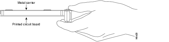

Handling the VAM2+

The VAM2+ is a single-width circuit board mounted on a metal carrier. (see Figure 3-1).


Caution Always handle the VAM2+ by the carrier edges and handle; never touch the VAM2+ components or connector pins. (See Figure 3-1.)

Figure 3-1 Handling the VAM2+

Online Insertion and Removal (OIR)

Before removing the VAM2+, we recommend that you shut down the interface so that there is no traffic running through the VAM2+ when it is removed. Removing an VAM2+ while traffic is flowing through the ports can cause system disruption.


Caution When using IPSec stateful failover, removing a hardware module, such as a single VAM2+ will cause the device to failover and reload.


Caution Online removal will disrupt existing tunnels. You will need to reestablish your tunnels. See Site-to-Site and Extranet VPN Business Scenarios at http://www.cisco.com/univercd/cc/td/doc/product/core/7100/swcg/6342gre.htm#xtocid247834 for additional information on configuring tunnels.

Warnings and Cautions

Observe the following warnings and cautions when installing or removing VPN acceleration modules.


Warning Blank faceplates and cover panels serve three important functions: they prevent exposure to hazardous voltages and currents inside the chassis; they contain electromagnetic interference (EMI) that might disrupt other equipment; and they direct the flow of cooling air through the chassis. Do not operate the system unless all cards, faceplates, front covers, and rear covers are in place.


Warning The safety cover is an integral part of the product. Do not operate the unit without the safety cover installed. Operating the unit without the cover in place will invalidate the safety approvals and pose a risk of fire and electrical hazards.


Warning Before working on equipment that is connected to power lines, remove jewelry (including rings, necklaces, and watches). Metal objects will heat up when connected to power and ground and can cause serious burns or weld the metal object to the terminals.


Warning Keep hands and fingers out of the power supply bays. High voltage is present on the power backplane when the system is running.


VAM2+ Removal and Installation

This section describes how to remove and install the VAM2+, and covers the following topics:

Cisco 7200VXR Series Routers

Cisco 7301 Router


Warning When performing the following procedures, wear a grounding wrist strap to avoid ESD damage to the card. Some platforms have an ESD connector for attaching the wrist strap. Do not directly touch the midplane or backplane with your hand or any metal tool, or you could shock yourself.


Note After powering off the router, wait at least 30 seconds before powering it on again.


Cisco 7200VXR Series Routers

Follow these steps to remove and insert the VAM2+ in the Cisco 7200VXR series routers:


Step 1 Turn the power switch to the off position and then remove the power cable. (Optional on Cisco 7200VXR series routers; see Caution, above)

Step 2 Attach an ESD wrist strap between you and an unpainted chassis surface.

Step 3 Place the VAM2+ retaining lever in the unlocked position. (See 1 in Figure 3-2.)

Figure 3-2 Placing the Port Adapter Lever in the Unlocked/Locked Position - Cisco 7206VXR Shown

1

Unlocked position

2

Locked position


Step 4 Grasp the handle of the VAM2+ and pull the VAM2+ from the router. If you are removing a blank port adapter, pull it completely out of the chassis slot.

Step 5 Carefully align the new VAM2+ carrier between the upper and the lower edges of the port adapter slot. (See Figure 3-3.)


Caution To prevent jamming the carrier between the upper and the lower edges of the port adapter slot, and to ensure that the edge connector at the rear of the VAM2+ mates with the connection at the rear of the port adapter slot, make certain that the carrier is positioned correctly, as shown in the cutaway in Figure 3-3.

Figure 3-3 Sliding the VAM2+ into the Port Adapter Slot - Cisco 7206VXR Shown

1

Upper edge of the port adapter slot


Step 6 Slide the new VAM2+ into the port adapter slot until it is seated in the router midplane.


Caution Do not allow the VAM2+ components to come in contact with the system board or the VAM2+ could be damaged.

Step 7 After the VAM2+ is properly seated, lock the VAM2+ in place, as shown in 2 of Figure 3-2.


Note If a retaining lever does not move to the locked position, the module is not completely seated in the midplane. Carefully pull the module out of the slot, reinsert it, and move the retaining lever or other mechanism to the locked position. See Figure 3-2.


Caution To ensure the proper flow of cooling air across the internal components, make sure a blank service adapter filler is installed in any unoccupied port adapter slots (part number 800-20675-01).

Step 8 If you powered off the router:

a. Reattach the power cable, and place the cable through any cable support brackets.

b. Power on the router by turning the power switch to the on position.


This completes the removal and installation procedure of the VAM2+ from the Cisco 7200VXR series routers.

Cisco 7301 Router

Use Figure 3-4 and follow the steps below to remove and insert an VAM2+ in the Cisco 7301 router:


Note The Cisco 7301 supports a single VAM2+ or port adapter.


Figure 3-4 Cisco 7301 Port Adapter/VAM2+ Slot

1

Latch

3

Slot guides

2

VAM2+ partially removed

4

Ground for ESD wrist strap banana jack


Step 1 Use an ESD wrist strap to ground yourself to the router. A banana jack ground is to the left of the power switch.

Step 2 To remove a VAM2+, use a Phillips screwdriver to turn the screw holding the latch. The screw should be loose enough to allow the latch to rotate to an unlocked position (1). The latch can rotate 360o.

Step 3 Grasp the handle and pull the VAM2+ (2) from the router, about halfway out of its slot. If you are removing a blank port adapter, pull the blank port adapter completely out of the chassis slot.


Caution The VAM2+ must slide into the slot guides (3) close to the chassis lid. Do not allow the VAM2+ components to come in contact with the system board or the VAM2+ could be damaged.

Step 4 To insert the VAM2+, carefully align the VAM2+ carrier in the slot guides (3), then carefully slide the VAM2+ all the way into the slot until the VAM2+ is seated.

Step 5 After the VAM2+ is properly seated, turn and secure the latch in the upright, locked position (1). Tighten the screw to ensure the VAM2+ remains firmly in place.

Step 6 Reconnect the power cables.

Step 7 Press the power switch to the ON position to power on the router.


This completes the removal and installation procedure of the VAM2+ from the Cisco 7301 router.


hometocprevnextglossaryfeedbacksearchhelp

Posted: Tue Apr 5 12:41:00 PDT 2005
All contents are Copyright © 1992--2005 Cisco Systems, Inc. All rights reserved.
Important Notices and Privacy Statement.