|
|

This chapter will help you confirm that you have correctly installed the software for your workgroup EISA SCO adapter. But first make sure that you have followed all the steps in the Workgroup CDDI/FDDI EISA Adapter Hardware Installation and the chapter, "Installing the Adapter Software," earlier in this guide.
This section assumes that you have rebooted your SCO workstation. Refer to your SCO Open System/SCO Open Server, System Administrator's Guide Operating System, Networking, and DOS Services document for the correct way to reboot your system.
During the initialization process, you will see messages that indicate that the hardware is installed properly. The Institute for Electrical and Electronics Engineers (IEEE) and FDDI addresses that are unique to each EISA SCO adapter are read from the FDDI interface.
The following display is from a SCO workstation startup screen.
device        address             vector          dma        comments
----------------------------------------------------------------------------------------------------
%fpu          -                   13              -          type-80387
.
.
. (information omitted)
.
.
.
/fddi 0x 2c80-080-0x2cA0          11               -          fddi0 dr:1.1 hw4.2 fw4.3 diag:0x001
fddi0mac:00:40:0B:40:82:2A
%type         -                   -                -          typw=S ha=0id2 lu=0 hd=arad
fddi: ring up
.
.
. (information omitted)
.
.
.
After the system is initialized, the login prompt appears. Log in to your system as usual.
Two diagnostic LEDs are mounted on each EISA SCO adapter. These LEDs indicate status and ring operation.
The status LED monitors the adapter's status. If this LED is on, the adapter has passed its internal diagnostics. This LED must be on for the adapter to function properly.
The ringop LED monitors ring operation. If this LED is on, the adapter is connected to the CDDI/FDDI ring. If this LED is not on, check that the adapter is connected to the concentrator and to the RJ-45 wall outlet. If both connections are good, check to see if there is a cable fault and if the concentrator is operational.
You can confirm the operation of the adapter in several ways. For example, you can use the ifconfig command to verify that the adapter connection is up and the IP, netmask, and broadcast addresses are correct. You can use the ping command to check if the adapter is connected and able to communicate with other devices on the network. You can use the FDDI status utility to confirm that the adapter hardware and software are installed and operating correctly.
Log into your system as follows:
Step 1 Log in to the system as root.
Step 2 Enter the password for the root login at the prompt.
Use the ifconfig command to display the current FDDI configuration.
The ifconfig command displays slightly different information, depending on the operating system software. Following is an example of the ifconfig command used with SCO workstation system software:
# ifconfig fddi0
fddi0: flags=23<UP,BROADCAST,NOTRAILERS>
        	 inet 198.133.219.103 netmask ffffff00 broadcast 198.133.219.255
#
where:
198.133.219.103 is the address you assigned in the /etc/hosts file.
You can use the ping command to determine if your adapter is connected to the network or other devices on the network. Typically, you will use the ping command to check the following devices:
Enter the ping command, as follows:
console# ping console-fddi
PING console-fddi.cisco.com (192.122.173.42): 56 data bytes
64 bytes from 192.122.173.42: icmp_seq=0 ttl=255 time=2 ms
64 bytes from 192.122.173.42: icmp_seq=1 ttl=255 time=2 ms
64 bytes from 192.122.173.42: icmp_seq=2 ttl=255 time=2 ms
64 bytes from 192.122.173.42: icmp_seq=3 ttl=255 time=2 ms
64 bytes from 192.122.173.42: icmp_seq=4 ttl=255 time=2 ms
64 bytes from 192.122.173.42: icmp_seq=5 ttl=255 time=2 ms
64 bytes from 192.122.173.42: icmp_seq=6 ttl=255 time=2 ms
64 bytes from 192.122.173.42: icmp_seq=7 ttl=255 time=3 ms
64 bytes from 192.122.173.42: icmp_seq=8 ttl=255 time=2 ms
64 bytes from 192.122.173.42: icmp_seq=9 ttl=255 time=2 ms
64 bytes from 192.122.173.42: icmp_seq=10 ttl=255 time=2 ms
64 bytes from 192.122.173.42: icmp_seq=11 ttl=255 time=2 ms
----console-fddi.cisco.com PING Statistics----
12 packets transmitted, 12 packets received, 0% packet loss
round-trip min/avg/max = 2/2/3 ms
console#
See Appendix B "Using the FDDI Status Utility" for information on how to confirm that the EISA SCO adapter hardware and software are installed and operating correctly.
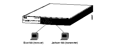
You can monitor the performance of the EISA SCO adapter using the following test setup (which is similar to Figure 3-1) and the ttcp utility.

In the following examples, refer to Figure 3-1.
The TCP measurements format of the ttcp command is as follows:
From the receiver:
Elvis-fddi: ttcp -r -v -R51000
From the transmitter:
Jackson-fddi: ttcp -t -v -S51000 Elvis-fddi
The UDP measurements format of the ttcp command is as follows:
From the receiver:
Elvis-fddi: ttcp -r -u -v -R51000
From the transmitter:
Jackson-fddi: ttcp -t -u -v -S51000 Elvis-fddi
|
|