cc/td/doc/product/cable/vod
hometocprevnextglossaryfeedbacksearchhelp
PDF

Table Of Contents

Removing and Replacing a QAM Card in the Cisco uMG9820 QAM Gateway

Ausbauen und Ersetzen der QAM-Karte des Cisco uMG9820 QAM Gateway


Quick Start Guide

Removing and Replacing a QAM Card in the Cisco uMG9820 QAM Gateway


Hinweis Sie finden diese Anweisungen auf Deutsch unter „ ".


Note For related documents, refer to Cisco uMG9820 QAM Gateway at the following URL: http://www.cisco.com/unvaried/cc/td/doc/product/cable/vod/umg9820/
index.htm


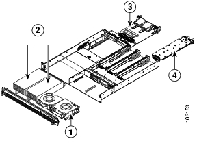
The following figure shows the locations of the field-replaceable units (FRUs) in the Cisco uMG9820. This procedure refers to Item 4.


Warning Hazardous voltage or energy is present on the backplane when the system is operating. Use caution when servicing. Statement 1034


Caution To prevent electrostatic discharge (ESD) damage, handle this module carefully. The RF connectors are particularly susceptible to damage from static electricity. You must be properly grounded before handling this ESD-sensitive product.

For this procedure, you do not need to turn off the power or remove the chassis from the rack. Replacing a QAM card does not cause a service outage on any of the other QAM cards.

To remove a QAM card:


Step 1 Use an ESD-preventive wrist strap, grounding the strap to bare metal on the rack or chassis.

Step 2 Disconnect all cables.

Step 3 Using a flat-blade screwdriver, loosen the two captive screws on the QAM card.

Step 4 Using the F-connectors, carefully pull the QAM card out.


To install a QAM card:


Step 1 Insert the QAM card into the chassis. Ensure that the edges of the QAM card fit into the card guides before sliding the card completely into the chassis.

Step 2 Using a flat-blade screwdriver, tighten the two captive screws on the QAM card.

Step 3 Connect any required cables.


Ausbauen und Ersetzen der QAM-Karte des Cisco uMG9820 QAM Gateway


Note To read these instructions in English, see "".


Hinweis Dokumente zu ähnlichen Themen finden Sie unter „Cisco uMG9820 QAM Gateway" auf der Website http://www.cisco.com/unvaried/cc/td/doc/product/cable/vod/umg9820/
index.htm
.


Die folgende Abbildung zeigt die herausnehmbaren Bauteile (FRUs) im Cisco uMG9820. Bei dem hier beschriebenen Verfahren geht es um Bauteil 4.


Warnung Wenn das System in Betrieb ist, treten auf der Rückwandplatine gefährliche Spannungen oder Energien auf. Vorsicht bei der Wartung. Statement 1034


Vorsicht Gehen Sie vorsichtig vor, um Schäden durch elektrostatische Entladung (ESD) zu vermeiden. Die RF-Stecker sind besonders anfällig für Schäden durch statische Elektrizität. Sorgen Sie für ausreichende Erdung, da das Produkt anfällig für elektrostatische Entladung ist.

Bei diesem Verfahren ist es nicht nötig, die Stromversorgung abzuschalten oder das Gehäuse vom Rack zu entfernen. Während des Ersetzens einer QAM-Karte wird der Betrieb der anderen QAM-Karten nicht unterbrochen.

So bauen Sie eine QAM-Karte aus:


Schritt 1 Verwenden Sie ein Erdungsarmband, und erden Sie dieses über ein Metallteil am Rack oder Gehäuse.

Schritt 2 Entfernen Sie alle Kabel.

Schritt 3 Lösen Sie die zwei Befestigungsschrauben der QAM-Karte mit einem Schlitzschraubendreher.

Schritt 4 Ziehen Sie die QAM-Karte mithilfe der F-Stecker vorsichtig heraus.


So installieren Sie eine QAM-Karte:


Schritt 1 Führen Sie die QAM-Karte in das Gehäuse ein. Bevor Sie die Karte vollständig in das Gehäuse einschieben, sollten Sie sicherstellen, dass die Kanten der QAM-Karte in die entsprechenden Führungsrinnen passen.

Schritt 2 Ziehen Sie die zwei Befestigungsschrauben der QAM-Karte mit einem Schlitzschraubendreher an.

Schritt 3 Schließen Sie alle erforderlichen Kabel an.


hometocprevnextglossaryfeedbacksearchhelp

Posted: Fri Oct 8 11:57:51 PDT 2004
All contents are Copyright © 1992--2004 Cisco Systems, Inc. All rights reserved.
Important Notices and Privacy Statement.