- Preface
- 1. General Overview
- 2. Command-Line Interface
- 3. Operations
- 4. Utilities
- 5. Configuring the Management Interface and Security
- Configuring the Management Ports
- Entering Management Interface Configuration Mode
- Configuring the Management Port Physical Parameters
- Configuring the Management Ports for Redundancy
- Management Interface Security
- Configuring the Available Interfaces
- SNMP Configuration and Management
- Passwords
- IP Configuration
- Time Clocks and Time Zone
- SNTP
- Domain Name (DNS) Settings
- Configuring the Management Port Physical Parameters
- 6. Configuring the Line Interface
- 7. Configuring the Connection
- 8. Configuring the RDR Formatter
- 9. Managing Subscribers
- 10. Redundancy and Fail-Over
- 11. Identifying And Preventing Distributed-Denial-Of-Service Attacks
- 12. Value Added Services (VAS) Traffic Forwarding
- VAS Traffic Forwarding Overview
- How VAS Traffic Forwarding Works
- VAS Redundancy
- VAS Status and VAS Health Check
- VAS Traffic Forwarding Topologies
- SNMP Support for VAS
- VAS Traffic Forwarding Configuration
- Monitoring VAS Traffic Forwarding
- Interactions Between VAS Traffic Forwarding and Other SCE Platform Features
- VAS over 10G
- 13. MPLS/VPN Support
- 14. Managing the SCMP
- A. Monitoring SCE Platform Utilization
- B. Proprietary MIB Reference
This preface describes who should read the Cisco Service Control Engine (SCE) Software Configuration Guide, how it is organized, and its document conventions.
|
Cisco Service Center Release |
Part Number |
Publication Date |
|---|---|---|
|
Release 3.0.5 |
OL-7827-05 |
November, 2006 |
Description of Changes
Added the following new feature:
The following sections were added or updated to explain various CLI commands that had not previously appeared in this guide:
|
Cisco Service Center Release |
Part Number |
Publication Date |
|---|---|---|
|
Release 3.0.3 |
OL-7827-04 |
May, 2006 |
Description of Changes
Added the following new features:
MPLS/VPN Support (including MPLS/VPN-related changes in Managing Subscribers and Configuring Tunneling Protocols).
The Proprietary MIB Reference was reorganized to reflect reorganization of the pcube Enterprise MIB.
|
Cisco Service Center Release |
Part Number |
Publication Date |
|---|---|---|
|
Release 3.0 |
OL-7827-03 |
December, 2005 |
Description of Changes
Added the following new features:
|
Cisco Service Center Release |
Part Number |
Publication Date |
|---|---|---|
|
Release 2.5.7 |
OL-7827-02 |
May, 2005 |
Description of Changes
Complete reorganization and revision of product documentation.
This guide is for experienced network administrators who are responsible for configuring and maintaining the SCE platform.
The major sections of this guide are as follows:
|
Chapter |
Title |
Description |
|---|---|---|
|
Chapter 1 |
Overview of SCE platform management. | |
|
Chapter 2 |
Detailed explanation of how to use the Cisco SCE Command-line Interface. | |
|
Chapter 3 |
Explanation of how to manage configurations, install applications and upgrade the system software. | |
|
Chapter 4 |
Explanation of the setup wizard and the user log, as well as of file operations. | |
|
Chapter 5 |
Explanation of how to configure the various management options: Telnet, SSH, and SNMP. Also how to configure the system time,Domain Name Settings, management IP address, and passwords. | |
|
Chapter 6 |
Explanation of how to configure tunneling, TOS marking, and traffic rules. | |
|
Chapter 7 |
Explanation of how to configure the connection mode, link mode, and failure behaviors. | |
|
Chapter 8 |
Explanation of how to configure the RDR Formatter so that RDRs are sent to the proper destinations. | |
|
Chapter 9 |
Explanation of how to import and export subscriber information and how to monitor subscribers. | |
|
Chapter 10 |
Explanation of how to configure and manage a redundant system. This chapter applies only to the SCE 2000 platform. | |
|
Chapter 11 |
Identifying And Preventing Distributed-Denial-Of-Service Attacks |
Explanation of how to configure attack filtering. |
|
Chapter 12 |
Explanation of Value Added Services (VAS) and how to configure VAS traffic forwarding. | |
|
Chapter 13 |
Explanation of MPLS/VPN support, and how to configure and monitor MPLS/VPN subscribers and support. | |
|
Chapter 14 |
Explanation of Service Control Management Protocol (SCMP), which is a protocol that integrates the SCE platform and the ISG (Intelligent Service Gateway) functionality of the Cisco routers. It also explains how to configure and manage SCMP, SCMP peer devices and the RADIUS client. | |
|
Appendix A |
Explanation of how to monitor SCE platforms that are installed in real traffic. | |
|
Appendix B |
Definition of the proprietary Service Control Enterprise MIB. |
Your SCE platform and the software running on it contain extensive features and functionality, which are documented in the following resources:
For further information regarding the Service Control CLI and a complete listing of all CLI commands, refer to the Cisco Service Control Engine (SCE) CLI Command Reference
For complete installation information, including initial configuration, refer to the relevant installation guide:
Cisco SCE 2000 4xGBE Installation and Configuration Guide
Cisco SCE 2000 4/8xFE Installation and Configuration Guide
Cisco SCE 1000 2xGBE Installation and Configuration Guide
Note
You can access Cisco software configuration and hardware installation and maintenance documentation on the World Wide Web at Cisco Website URL. Translated documentation is available at the following URL: International Cisco Website
For initial installation and startup information, refer to the relevant quick start guide:
Cisco SCE 2000 4xGBE Quick Start Guide
Cisco SCE 2000 4/8xFE Quick Start Guide
Cisco SCE 1000 2xGBE Quick Start Guide
For international agency compliance, safety, and statutory information for wide-area network (WAN) interfaces for the SCE platform, refer to the regulatory and safety information document:
Regulatory Compliance and Safety Information for the Cisco Service Control Engine (SCE)
For installation and configuration of the other components of the Service Control Management Suite refer to:
Cisco Service Control Management Suite Subscriber Manager User Guide
Cisco Service Control Management Suite Collection Manager User Guide
Cisco Service Control Application for Broadband User Guide
Cisco Service Control Application Reporter User Guide
To view Cisco documentation or obtain general information about the documentation, refer to the following sources:
Obtaining Documentation
The Cisco Information Packet that shipped with your SCE platform.
This document uses the following conventions:
|
Convention |
Description |
|---|---|
|
boldface font |
Commands and keywords are in boldface. |
|
italic font |
Arguments for which you supply values are in italics. |
|
[ ] |
Elements in square brackets are optional. |
|
{x | y | z} |
Alternative keywords are grouped in braces and separated by vertical bars. |
|
[x | y | z] |
Optional alternative keywords are grouped in brackets and separated by vertical bars. |
|
string |
A nonquoted set of characters. Do not use quotation marks around the string, or the string will include the quotation marks. |
|
|
Terminal sessions and information that the system displays are in |
|
|
Information you must enter is in |
|
|
Arguments for which you supply values are in |
|
< > |
Nonprinting characters, such as passwords, are in angle brackets. |
|
[ ] |
Default responses to system prompts are in square brackets. |
|
!, # |
An exclamation point (!) or a pound sign (#) at the beginning of a line of code indicates a comment line. |
Note
Means reader take note. Notes contain helpful suggestions or references to materials not covered in this manual.
Caution
Means reader be careful. In this situation, you might do something that could result in equipment damage or loss of data.
Warning
Means reader be warned. In this situation, you might do something that could result in bodily injury.
The following sections provide sources for obtaining documentation from Cisco Systems.
You can access the most current Cisco documentation on the World Wide Web at the following sites:
Cisco documentation and additional literature are available in a CD-ROM package that ships with your product. The Documentation CD-ROM is updated monthly and may be more current than printed documentation. The CD-ROM package is available as a single unit or as an annual subscription.
Cisco documentation is available in the following ways:
Registered Cisco Direct Customers can order Cisco Product documentation from the networking Products MarketPlace:
Registered Cisco.com users can order the Documentation CD-ROM through the online Subscription Store:
Nonregistered Cisco.com users can order documentation through a local account representative by calling Cisco corporate headquarters (California, USA) at 408 526-7208 or, in North America, by calling 800 553-NETS(6387).
If you are reading Cisco product documentation on the World Wide Web, you can submit technical comments electronically. Click Feedback in the toolbar and select Documentation. After you complete the form, click Submit to send it to Cisco.
You can e-mail your comments to bug-doc@cisco.com.
To submit your comments by mail, use the response card behind the front cover of your document, or write to the following address:
Attn Document Resource Connection Cisco Systems, Inc. 170 West Tasman Drive San Jose, CA 95134-9883
We appreciate your comments.
Cisco provides Cisco.com as a starting point for all technical assistance. Customers and partners can obtain documentation, troubleshooting tips, and sample configurations from online tools. For Cisco.com registered users, additional troubleshooting tools are available from the TAC website.
Cisco.com is the foundation of a suite of interactive, networked services that provides immediate, open access to Cisco information and resources at any time, from anywhere in the world. This highly integrated Internet application is a powerful, easy-to-use tool for doing business with Cisco.
Cisco.com provides a broad range of features and services to help customers and partners streamline business processes and improve productivity. Through Cisco.com, you can find information about Cisco and our networking solutions, services, and programs. In addition, you can resolve technical issues with online technical support, download and test software packages, and order Cisco learning materials and merchandise. Valuable online skill assessment, training, and certification programs are also available.
Customers and partners can self-register on Cisco.com to obtain additional personalized information and services. Registered users can order products, check on the status of an order, access technical support, and view benefits specific to their relationships with Cisco.
To access Cisco.com, go to http://www.cisco.com.
The Cisco Technical Assistance Center (TAC) website is available to all customers who need technical assistance with a Cisco product or technology that is under warranty or covered by a maintenance contract.
If you have a priority level 3 (P3) or priority level 4 (P4) problem, contact TAC by going to the TAC website http://www.cisco.com/tac.
P3 and P4 level problems are defined as follows:
P3—Your network is degraded. Network functionality is noticeably impaired, but most business operations continue.
P4—You need information or assistance on Cisco product capabilities, product installation, or basic product configuration.
In each of the above cases, use the Cisco TAC website to quickly find answers to your questions.
To register for Cisco.com, go to http://tools.cisco.com/RPF/register/register.do.
If you cannot resolve your technical issue by using the TAC online resources, Cisco.com registered users can open a case online by using the TAC Case Open tool at http://www.cisco.com/tac/caseopen.
If you have a priority level 1 (P1) or priority level 2 (P2) problem, contact TAC by telephone and immediately open a case. To obtain a directory of toll-free numbers for your country, go to http://www.cisco.com/warp/public/687/Directory/DirTAC.shtml.
P1 and P2 level problems are defined as follows:
P1—Your production network is down, causing a critical impact to business operations if service is not restored quickly. No workaround is available.
P2—Your production network is severely degraded, affecting significant aspects of your business operations. No workaround is available.
This chapter provides a general overview of the Cisco Service Control solution. It introduces the Cisco Service Control concept and the Service Control capabilities. It also briefly describes the hardware capabilities of the Service Control Engine (SCE) platform and the Cisco specific applications that together compose the total Cisco Service Control solution.
The Cisco Service Control solution is delivered through a combination of purpose-built hardware and specific software solutions that address various service control challenges faced by service providers. The SCE platform is designed to support classification, analysis, and control of Internet/IP traffic.
Service Control enables service providers to create profitable new revenue streams while capitalizing on their existing infrastructure. With the power of Service Control, service providers have the ability to analyze, charge for, and control IP network traffic at multigigabit wire line speeds. The Cisco Service Control solution also gives service providers the tools they need to identify and target high-margin content-based services and to enable their delivery.
As the downturn in the telecommunications industry has shown, IP service providers’ business models need to be reworked to make them profitable. Having spent billions of dollars to build ever larger data links, providers have incurred massive debts and faced rising costs. At the same time, access and bandwidth have become commodities where prices continually fall and profits disappear. Service providers have realized that they must offer value-added services to derive more revenue from the traffic and services running on their networks. However, capturing real profits from IP services requires more than simply running those services over data links; it requires detailed monitoring and precise, real-time control and awareness of services as they are delivered. Cisco provides Service Control solutions that allow the service provider to bridge this gap.
Service providers of any access technology (DSL, cable, mobile, and so on) targeting residential and business consumers must find new ways to get maximum leverage from their existing infrastructure, while differentiating their offerings with enhanced IP services.
The Cisco Service Control Application for Broadband adds a new layer of service intelligence and control to existing networks that can:
Report and analyze network traffic at subscriber and aggregate level for capacity planning
Provide customer-intuitive tiered application services and guarantee application SLAs
Implement different service levels for different types of customers, content, or applications
Identify network abusers who are violating the Acceptable Use Policy
Identify and manage peer-to-peer, NNTP (news) traffic, and spam abusers
Enforce the Acceptable Use Policy (AUP)
Integrate Service Control solutions easily with existing network elements and BSS/OSS systems
The core of the Cisco Service Control solution is the purpose-built network hardware device: the Service Control Engine (SCE). The core capabilities of the SCE platform, which support a wide range of applications for delivering Service Control solutions, include:
Subscriber and application awareness—Application-level drilling into IP traffic for real-time understanding and controlling of usage and content at the granularity of a specific subscriber.
Subscriber awareness—The ability to map between IP flows and a specific subscriber in order to maintain the state of each subscriber transmitting traffic through the SCE platform and to enforce the appropriate policy on this subscriber’s traffic.
Subscriber awareness is achieved either through dedicated integrations with subscriber management repositories, such as a DHCP or a Radius server, or via sniffing of Radius or DHCP traffic.
Application awareness—The ability to understand and analyze traffic up to the application protocol layer (Layer 7).
For application protocols implemented using bundled flows (such as FTP, which is implemented using Control and Data flows), the SCE platform understands the bundling connection between the flows and treats them accordingly.
Application-layer, stateful, real-time traffic control—The ability to perform advanced control functions, including granular BW metering and shaping, quota management, and redirection, using application-layer stateful real-time traffic transaction processing. This requires highly adaptive protocol and application-level intelligence.
Programmability—The ability to quickly add new protocols and easily adapt to new services and applications in the ever-changing service provider environment. Programmability is achieved using the Cisco Service Modeling Language (SML).
Programmability allows new services to be deployed quickly and provides an easy upgrade path for network, application, or service growth.
Robust and flexible back-office integration—The ability to integrate with existing third-party systems at the Service Provider, including provisioning systems, subscriber repositories, billing systems, and OSS systems. The SCE provides a set of open and well-documented APIs that allows a quick and robust integration process.
Scalable high-performance service engines—The ability to perform all these operations at wire speed.
The SCE family of programmable network devices is capable of performing application-layer stateful-flow inspection of IP traffic, and controlling that traffic based on configurable rules. The SCE platform is a purpose-built network device that uses ASIC components and RISC processors to go beyond packet counting and delve deeper into the contents of network traffic. Providing programmable, stateful inspection of bidirectional traffic flows and mapping these flows with user ownership, the SCE platforms provide real-time classification of network usage. This information provides the basis of the SCE platform advanced traffic-control and bandwidth-shaping functionality. Where most bandwidth shaper functionality ends, the SCE platform provides more control and shaping options, including:
Layer 7 stateful wire-speed packet inspection and classification
Robust support for over 600 protocols and applications, including:
General—HTTP, HTTPS, FTP, TELNET, NNTP, SMTP, POP3, IMAP, WAP, and others
P2P file sharing—FastTrack-KazaA, Gnutella, BitTorrent, Winny, Hotline, eDonkey, DirectConnect, Piolet, and others
P2P VoIP—Skype, Skinny, DingoTel, and others
Streaming and Multimedia—RTSP, SIP, HTTP streaming, RTP/RTCP, and others
Programmable system core for flexible reporting and bandwidth control
Transparent network and BSS/OSS integration into existing networks
Subscriber awareness that relates traffic and usage to specific customers
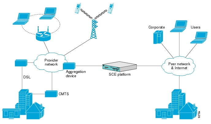
The following diagram illustrates a common deployment of an SCE platform in a network.
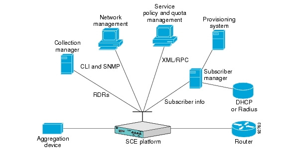
The Cisco Service Control solution includes a complete management infrastructure that provides the following management components to manage all aspects of the solution:
Network management
Subscriber management
Service Control management
These management interfaces are designed to comply with common management standards and to integrate easily with existing OSS infrastructure.
Cisco provides complete network FCAPS (Fault, Configuration, Accounting, Performance, Security) Management.
Two interfaces are provided for network management:
Command-line interface (CLI)—Accessible through the Console port or through a Telnet connection, the CLI is used for configuration and security functions.
SNMP—Provides fault management (via SNMP traps) and performance monitoring functionality.
Service configuration management is the ability to configure the general service definitions of a service control application. A service configuration file containing settings for traffic classification, accounting and reporting, and control is created and applied to an SCE platform. The SCA BB application provides tools to automate the distribution of these configuration files to SCE platforms. This simple, standards-based approach makes it easy to manage multiple devices in a large network.
Service Control provides an easy-to-use GUI to edit and create these files and a complete set of APIs to automate their creation.
Where the Cisco Service Control Application for Broadband (SCA BB) enforces different policies on different subscribers and tracks usage on an individual subscriber basis, the Cisco Service Control Management Suite (SCMS) Subscriber Manager (SM) may be used as middleware software for bridging between the OSS and the SCE platforms. Subscriber information is stored in the SM database and can be distributed between multiple platforms according to actual subscriber placement.
The SM provides subscriber awareness by mapping network IDs to subscriber IDs. It can obtain subscriber information using dedicated integration modules that integrate with AAA devices, such as Radius or DHCP servers.
Subscriber information may be obtained in one of two ways:
Push Mode—The SM pushes subscriber information to the SCE platform automatically upon logon of a subscriber.
Pull Mode—The SM sends subscriber information to the SCE platform in response to a query from the SCE platform.
The Cisco Service Control solution generates usage data and statistics from the SCE platform and forwards them as Raw Data Records (RDRs), using a simple TCP-based protocol (RDR-Protocol). The Cisco Service Control Management Suite (SCMS) Collection Manager (CM) software implements the collection system, listening in on RDRs from one or more SCE platforms and processing them on the local machine. The data is then stored for analysis and reporting functions, and for the collection and presentation of data to additional OSS systems such as billing.
This chapter describes how to use the SCE platform Command-Line Interface (CLI), its hierarchical structure, authorization levels and its help features. The Command-Line Interface is one of the SCE platform management interfaces.
To obtain a list of commands that are available for each command mode, enter a question mark (?) at the system prompt. You also can obtain a list of keywords and arguments associated with any command using the context-sensitive help feature.
The following table lists commands you can enter to get help that is specific to a command mode, a command, a keyword, or an argument.
Table 2.1. Getting Help
|
Command |
Purpose |
|---|---|
|
abbreviated-command-entry? |
Obtain a list of commands that begin with a particular character string. (Do not leave a space between the command and question mark.) |
|
abbreviated-command-entry<Tab> |
Complete a partial command name. |
|
? |
List all commands available for a particular command mode. |
|
command ? |
List the keywords associated with the specified command. Leave a space between the command and question mark. |
|
command keyword ? |
List the arguments associated with the specified keyword. Leave a space between the keyword and question mark. |
When using the CLI there are two important concepts that you must understand in order to navigate:
Authorization Level — Indicates the level of commands you can execute. A user with a simple authorization level can only view some information in the system, while a higher level administrator can actually make changes to configuration.
This manual documents commands at the User, Viewer, and Admin authorization level. See CLI Command Hierarchy.
Command Hierarchy Level — Provides you with a context for initiating commands. Commands are broken down into categories and you can only execute each command within the context of its category. For example, in order to configure parameters related to the Line Card, you need to be within the LineCard Interface Configuration Mode. See CLI Command Hierarchy.
The following sections describe the available Authorization and Command Hierarchy Levels and how to maneuver within them.
The on-screen prompt indicates both your authorization level and your command hierarchy level, as well as the assigned host name. See Prompt Indications.
Note
Throughout the manual, SCE is used as the sample host name.
The set of all CLI commands is grouped in hierarchical order, according to the type of the commands. The first three levels in the hierarchy are the User Exec, Viewer, and Privileged Exec modes. These are non-configuration modes in which the set of available commands enables the monitoring of the SCE platform, file system operations, and other operations that cannot alter the configuration of the SCE platform.
The next levels in the hierarchy are the Global and Interface configuration modes, which hold a set of commands that control the global configuration of the SCE platform and its interfaces. Any of the parameters set by the commands in these modes should be saved in the startup configuration, such that in the case of a reboot, the SCE platform restores the saved configuration.
The following tableshows the available CLI modes.
Table 2.2. CLI Modes
|
Mode |
Description |
Level |
Prompt indication |
|---|---|---|---|
|
User Exec |
Initial mode with very limited functionality. |
User |
SCE> |
|
Viewer |
Monitoring (show commands). |
Viewer |
SCE> |
|
Privileged Exec |
General administration; file system manipulations and control of basic parameters that do not change the configuration of the SCE platform. |
Admin |
SCE# |
|
Global Configuration |
Configuration of general system parameters, such as DNS, host name, and time zone. |
Admin |
SCE |
|
Management Interface Configuration |
Configuration of management interface parameters, such as the Ethernet interface properties and selection of the active port. |
Admin |
SCE |
|
Interface Configuration |
Configuration of specific system interface parameters, such as the Line Card, and the Ethernet interfaces. |
Admin |
SCE |
|
Line Configuration |
Configuration of Telnet lines, such as an access-list. |
Admin |
SCE |
When you login to the system, you have the User authorization level and enter User Exec mode. Changing the authorization level to Viewer automatically moves you to Viewer mode. In order to move to any of the configuration modes, you must enter commands specific to that mode.
The list of available commands in each mode can be viewed using the question mark ‘?’ at the end of the prompt.
The figure below, illustrates the hierarchical structure of the CLI modes, and the CLI commands used to enter and exit a mode.
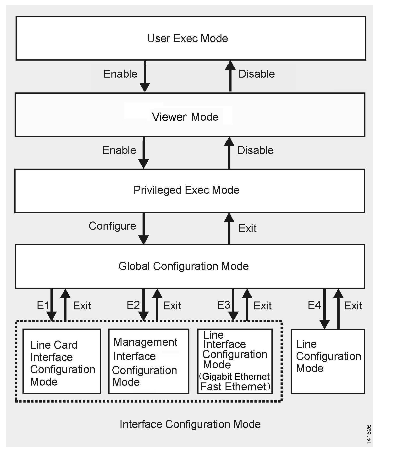
The following commands are used to enter the different configure interface modes and the Line Configuration Mode:
E1
interface LineCard 0E2
interface Mng0/1or0/2(management port, all platforms)E3
interface GigabitEthernet0/1or0/2(line ports, SCE 1000 platform)E3
interface GigabitEthernet0/1,0/2, 0/3,or0/4(line ports, SCE 2000 4xGBE platform)E3
interface FastEthernet0/1,0/2, 0/3, or 0/4E4
line vty 0
Note
Although the system supports up to five concurrent Telnet connections, you cannot configure them separately. This means that any number you enter in the line vty command (0, 1, 2, 3 or 4) will act as a 0 and configure all five connections together.
Note
In order for the auto-completion feature to work, when you move from one interface configuration mode to another, you must first exit the current interface configuration mode (as illustrated in the above figure).
Example:
This example illustrates moving into and out of configuration modes as follows:
Enter global configuration mode
Configure the SCE platform time zone
Enter Mng Interface configuration mode for Mng port 1
Configure the speed of the management interface
Exit the Mng Interface configuration mode to the global configuration mode
Enter the LineCard Interface configuration
Define the link mode.
Exit LineCard Interface configuration mode to the global configuration mode
Exit global configuration mode
SCE#configure
SCE(config)#clock timezone PST -10
SCE(config)#interface Mng 0/1
SCE(config if)#speed 100
SCE(config if)#exit
SCE(config)#interface LineCard 0
SCE(config if)#link-mode all-links forwarding
SCE(config if)#exit
SCE(config)#exit
SCE#The SCE platform has four authorization levels, which represent the user access permissions. When you initially connect to the SCE platform, you automatically have the most basic authorization level, that is User, which allows minimum functionality.
In order to monitor the system, you must have Viewer authorization, while in order to perform administrative functions on the SCE platform, you must have Admin or Root authorization. A higher level of authorization is accessed by logging in with appropriate password, as described in the procedures below.
In each authorization level, all the commands of the lower authorization layers are available in addition to commands that are authorized only to the current level.
Note
This manual covers the functions that can be performed by the Admin level user, unless otherwise noted.
The following CLI commands are related to authorization levels:
enable
disable
Each authorization level has a value (number) corresponding to it. When using the CLI commands, use the values, not the name of the level, as shown in the following table.
Table 2.3. Authorization Levels
|
Level |
Description |
Value |
Prompt |
|---|---|---|---|
|
User |
Password required. This level enables basic operational functionality. |
0 |
> |
|
Viewer |
Password required. This level enables monitoring functionality. All show commands are available to the Viewer authorization level, with the exception of those that display password information. |
5 |
> |
|
Admin |
Password required. For use by general administrators, the Admin authorization level enables configuration and management of the SCE platform. |
10 |
# |
|
Root |
Password required. For use by technical field engineers, the Root authorization level enables configuration of all advanced settings, such as debug and disaster recovery. The Root level is used by technical engineers only and is not documented in this manual. |
15 |
#> |
To change from User to Viewer level authorization:
From the
SCE>prompt, typeenable 5and press Enter.The system prompts for a password by showing the prompt
Password:Type in the password for the Viewer level and press Enter.
Note that the password is an access-level authorization setting, not an individual user password.
The system prompt
SCE>does not change when you move from User to Viewer level.
A telnet session begins with a request for password, and will not continue until the proper user password is supplied. This enhances the security of the system by not revealing its identity to unauthorized people.
To log in with Admin level authorization:
Initiate a telnet connection.
A
Password:prompt appears. Type in the user level password and press Enter.The
SCE>prompt appears.You now have user level authorization.
From the
SCE>prompt, typeenable 10and press Enter.The system prompts for a password by showing the prompt
Password:Type in the password for the Admin level and press Enter.
Note that the password is an access-level authorization setting, not an individual user password.
The system prompt changes to
SCE#to show you are now in Admin level.
Example:
The following example illustrates how to change the authorization level from User to Admin, and then revert back to Viewer. No password is required for moving to a lower authorization level.
SCE>enable 10
Password:  cisco
SCE#disable
SCE>The on-screen prompt indicates your authorization level, your command hierarchy level, and the assigned host name. The structure of the prompt is:
<hostname(mode-indication)level-indication>
Authorization levels are indicated as follows:
|
This prompt... |
Indicates this... |
|---|---|
|
> |
indicates User and Viewer levels |
|
# |
indicates Admin level |
|
#> |
indicates Root level |
Command hierarchy levels are indicated as follows:
|
This command hierarchy... |
Is indicated as... |
|---|---|
|
User Exec |
|
|
Privileged Exec |
|
|
Global Configuration |
|
|
Interface Configuration |
|
|
Line Configuration |
|
Example:
The prompt MySCE(config if)# indicates:
The name of the SCE platform is
MySCEThe current CLI mode is Interface configuration mode
The user has Admin authorization level
This section describes how to revert to a previous mode.
To exit from one authorization level to the previous one, use the disable command.
To exit from one mode to another with the Admin authorization level (these are the various configuration modes), use the exit command.
To exit from the Privileged Exec mode and revert to the Viewer mode:
At the
SCE#prompt, typedisable, and press Enter.The
SCE>prompt for the Viewer and User Exec mode appears.
To exit from the Global Configuration Mode:
At the
SCE(config)#prompt, typeexit, and press Enter.The appropriate prompt for the previous level appears.
Example:
The following example shows the system response when you exit the Interface Configuration mode.
SCE(config if)#exit
SCE(config)#The components that are configured by the Interface Configuration Modes are:
Card
LineCard —
Interface LineCard 0The LineCard interface configures the main functionality of viewing and handling traffic on the line.
Ports
Telnet
Line Configuration Mode —
Line vty 0The Line Configuration Mode enables you to configure Telnet parameters.
The SCE platform contains the following physical port interfaces:
Management:
Interface Mng 0/1 or 0/2The Management Interface mode configures the settings for the interface to a remote management console. The two management ports support management interface redundancy.
The following commands are used to configure the management port:
ip address
duplex
speed
active-port (SCE 2000 platform only)
Fast Ethernet (SCE 2000 4/8xFE):
Interface FastEthernet 0/1, 0/2, 0/3, or 0/4The FastEthernet Interface mode configures the settings for the FastEthernet interface to the Internet traffic on the wire. Each of the four ports can be set individually.
The following commands are used to configure the Fast Ethernet line ports:
bandwidth
duplex
queue
speed
Gigabit Ethernet (SCE 1000 platform):
Interface GigabitEthernet 0/1,or0/2The GigabitEthernet Interface mode configures the settings for the GigabitEthernet interface to the Internet traffic on the wire. Each of the two ports can be set individually.
Gigabit Ethernet (SCE 2000 4xGBE platform):
Interface GigabitEthernet 0/1,0/2, 0/3, or 0/4The GigabitEthernet Interface mode configures the settings for the GigabitEthernet interface to the Internet traffic on the wire. Each of the four ports can be set individually.
The following commands are used to configure the Gigabit Ethernet line ports:
auto-negotiate (GigabitEthernet only)
bandwidth
queue
Note
You must specify the slot number/interface number when referencing any interface. The slot number is always 0, and the interfaces are numbered as follows: Management Interface: 1,2 Ethernet Line Interfaces: SCE 1000 platform: 1,2 SCE 2000 platform: 1,2,3,4
Before you can configure the parameters for the management interface, you must be in the Mng Interface Configuration Mode.
To enter Mng Interface Configuration Mode, complete the following steps:
To enter Global Configuration Mode, type
configureand press Enter.The
SCE(config)#prompt appears.Type
interface Mng [0/1|0/2]and press Enter.The
SCE(config if)#prompt appears.The system prompt changes to reflect the higher level mode.
The following procedure is for entering Line Card Interface Configuration mode. The procedures for entering the other interfaces are the same except for the interface command as described above and in CLI Command Reference.
To enter LineCard Interface Configuration mode:
To enter Global Configuration Mode, at the
SCE#prompt, typeconfigure, and press Enter.The
SCE(config)#prompt appears.Type
interface LineCard0, and press Enter.The
SCE(config if)#prompt appears.To return to Global Configuration Mode, type
exitand press Enter.The
SCE(config)#prompt appears.To exit Global Configuration Mode, type
exitand press Enter.The
SCE#prompt appears.
To enter the FastEthernet Interface Configuration Mode:
To enter Global Configuration Mode, type
configureand press Enter.The
SCE(config)#prompt appears.For the SCE 2000, type
interface FastEthernet [0/1|0/2|0/3|0/4]and press Enter.The
SCE(config if)#prompt appears.
Example:
The following example shows how to enter Configuration Mode for the FastEthernet Interface number 3.
SCE(config)#interface FastEthernet 0/3
SCE(config if)#To enter the GigabitEthernet Interface Configuration Mode:
To enter Global Configuration Mode, type
configureand press Enter.The
SCE(config)#prompt appears.For the SCE 1000, type
interface GigabitEthernet [0/1|0/2]and press Enter.For the SCE 2000, type
interface GigabitEthernet [0/1|0/2|0/3|0/4]and press Enter.The
SCE(config if)#prompt appears.
Example:
The following example shows how to enter Configuration Mode for the GigabitEthernet Interface number 2.
SCE(config)#interface GigabitEthernet 0/2
SCE(config if)#There are four configuration command modes:
Global configuration mode
Management interface configuration mode
Interface configuration mode
Line configuration mode
When you are in one of these configuration modes, it is possible to execute an EXEC mode command (such as a show command) or a privileged EXEC (such as show running-config) without exiting to the relevant command mode. Use the 'do' command for this purpose.
To execute an exec mode command from a configuration command mode, use the following command:
At the
SCEconfig#(orSCEconfig if#)prompt, typedo<command>.The specified command executes without exiting to the appropriate exec command mode.
Example
The following example shows how to display the running configuration while in interface configuration mode.
SCEconfig if# do show running-configCLI provides context sensitive help. Two types of context sensitive help are supported:
Partial help
Argument help
To obtain a list of commands that begin with a particular character string, enter the abbreviated command entry immediately followed by a question mark (?). This form of help is called partial help, because it lists only the keywords or arguments that begin with the abbreviation you entered.
Example:
The following example illustrates how typing c? displays all available arguments that start with the letter c.
SCE(config)#snmp-server c?Community contactSCE(config)#snmp-server c
To obtain a list of command’s associated keywords or parameters, type a question mark (?) in place of a keyword or parameter on the command line.
Note that if <Enter> is acceptable input, the symbol <cr> represents the Enter key.
Example:
The following example illustrates how to get a list of all arguments or keywords expected after the command snmp-server.
SCE(config)#snmp-server ?
Community	Define community string
Contact		Set system contact
Enable		Enable the SNMP agent
Host   	 	Set traps destination
Location		Set system location
SCE(config)# snmp-server
When asking for help on particular parameter, the system informs you of the type of data that is an accepted legal value. The types of parameters supported are:
|
STRING |
When a String is expected, you can enter any set of characters or digits. If the string has a space as one of its characters, use double-quote (“) marks to enclose the string. |
|
DECIMAL |
Any decimal number. Positive number is assumed, for negative numbers use the “–” symbol. |
|
HEX |
A hexadecimal number; must start with either 0x or 0X. |
Example:
The following example illustrates the use of ? to get help on commands syntax. In this example, you can enter either the word running-config, or any name of a file, after the word copy.
SCE#copy ?
	running-config		Copy running configuration file
	STRING			Source file name
SCE#copyMany CLI commands offer the option of adding the word no before the command to disable the feature controlled by the command or revert it to its default configuration. This notation is shown in the CLI Command Reference as [no] to denote it is optional.
For example, no service telnetd disables the telnet server. Enabling the telnet server is done by typing service telnetd.
CLI maintains a history buffer of the most recent commands you used in the current CLI session for quick retrieval. Using the keyboard, you can navigate through your last commands, one by one, or all commands that start with a given prefix. By default, the system saves the last 30 commands you typed. You can change the number of commands remembered using the history size command.
To use the history functions, use the keys shown in the following table.
Table 2.4. Keyboard Shortcuts for History Functions
|
Arrow |
Shortcut |
Description |
|---|---|---|
|
Up arrow |
Ctrl-P |
Moves cursor to the previous command with the same prefix. |
|
Down arrow |
Ctrl-N |
Moves cursor to the next command with the same prefix as original. |
|
|
Ctrl-L Ctrl-R |
Re-display the current command line. |
The SCE platform has a number of keyboard shortcuts that make it easier to navigate and use the system. The following table shows the keyboard shortcuts available.
You can get a display the keyboard shortcuts at any time by typing help bindings.
Table 2.5. Keyboard Shortcuts
|
Description |
Shortcut Key |
|---|---|
|
Navigational shortcuts |
|
|
Move cursor one character to the right. |
CTRL-F /-> |
|
Move cursor one character to the left. |
CTRL-B /<- |
|
Move cursor one word to the right (forward). |
ESC-F |
|
Move cursor one word to the left (backward. |
ESC-B |
|
Move cursor to the start of the line. |
CTRL-A |
|
Move cursor to the end of the line. |
CTRL-E |
|
Editing shortcuts | |
|
Delete the character where the cursor is located. |
CTRL-D |
|
Delete from the cursor position to the end of the word. |
ESC-d |
|
Delete the character before the current location of the cursor. |
Backspace |
|
Delete the character before the current location of the cursor. |
CTRL-H |
|
Deletes from the cursor position to the end of the line |
CTRL-K |
|
Deletes all characters from the cursor to the beginning of the line |
CTRL-U |
|
Deletes all characters from the cursor to the beginning of the line. (Same functionality as CTRL-U.) |
CTRL-X |
|
Delete the word to the left of the cursor. |
CTRL-W |
|
Recall the last item deleted. |
CTRL-Y |
|
Completes the word when there is only one possible completion. |
<Tab> |
|
Completes the word when there is only one possible completion. (Same functionality as <Tab>.) |
CTRL-I |
The CLI interface features tab completion. When you type in the first letters of a command and type <Tab>, the system automatically fills in the rest of the command or keyword. This feature works only when there is one possible command that could be possible using the starting letters.
Example:
The letters snm followed by <Tab> will be completed to the command snmp-server.
SCE(config)#snm<Tab>
SCE(config)#snmp-server
If you type <Enter> instead of <Tab>, and there is no ambiguity, the system actually carries out the command which would be filled in by the rest of the word.
Example:
The following example displays how the system completes a partial (unique) command for the enable command. Because enable does not require any parameters, the system simply carries out the enable command when the user presses Enter.
SCE>en<Enter>
Password:
SCE#CLI enables saving ftp user name and password to be used in FTP operations—download and upload, per session.
These settings are effective during the current CLI session.
Example:
The following example illustrates how to set FTP password and user name and the use in these settings for getting a file named config.tmp from a remote station using FTP protocol.
SCE#ip ftp password vk
SCE#ip ftp username vk
SCE#copy ftp://@10.1.1.253/h:/config.tmp myconf.txt
connecting 10.1.1.253 (user name vk password vk) to retrieve config.tmp
SCE#Some commands, such as many show commands, may have many lines of output. There are several ways of managing the command output:
Scrolling options — When the command output is too large to be displayed all at once, you can control whether the display scrolls line by line or refreshes the entire screen.
Filtering options — You can filter the output so that output lines are displayed only if they include or exclude a specified expression.
Redirecting to a file — You can send the output to a specified file
The output of some show and dir commands is quite lengthy and cannot all be displayed on the screen at one time. Commands with many lines of output are displayed in chunks of 24 lines. You can choose to scroll the display line by line or refresh the entire screen. At the prompt after any line, you can type one of the following keys for the desired action:
<Enter>– show one more line
<Space> – show 24 more lines (a new chunk)
<g> – Stop prompting for more
<?> – Display a help string showing possible options
Any other key – quit showing the file
You can filter the output of certain commands, such as show, more, and dir, so that output lines are displayed only if they include or exclude a specified expression. The filtering options are as follows:
include — Shows all lines that include the specified text.
exclude — Does not show any lines that include the specified text.
begin — Finds the first line that includes the specified text, and shows all lines starting from that line. All previous lines are excluded.
The syntax of filtered commands is as follows:
<command> | include <expression>
<command> | exclude <expression>
<command> | begin <expression>
The <expression> in these commands is case sensitive.
Example
Following is an example of how to filter the show version command to display only the last part of the output, beginning with the version information.
SCE# show version begin revisionYou can redirect the output of commands, such as show, more, and dir, to a file. When writing the output of these commands to a file, you can specify either of the following options:
redirect — The new output of the command will overwrite the existing contents of the file.
append — The new output of the command will be appended to the existing contents of the file.
The syntax of redirection commands is as follows:
<command> | redirect <file-name><command> | append <file-name>Example
Following is an example of how to do the following:
Filter the
morecommand to display from a csv subscriber file only the gold package subscribers.Redirect that output to a file named current_gold_subscribers. The output should not overwrite existing entries in the file, but should be appended to the end of the file.
SCE#more subscribers_10.10.2004 include gold append current_gold_subscribers
The CLI scripts feature allows you to record several CLI commands together as a script and play it back. This is useful for saving repeatable sequence of commands , such as software upgrade. For example, if you are configuring a group of SCE platforms and you want to run the same configuration commands on each platform, you could create a script on one platform and run it on all the other SCE platforms.
The available script commands are:
script capture script stop script print script runTo create a script:
At the
SCE#prompt, typescript capturesample1.scrwheresample1.scris the name of the script.Perform the actions you want to be included in the script.
Type
script stop.The system saves the script.
Example:
The following is an example of recording a script for upgrading software.
SCE#script capture upgrade.scrSCE#configureSCE(config)#boot system new.pkgVerifying package file...Package file verified OK.SCE(config)#exitSCE#copy running-config startup-configWriting general configuration file to temporary location...Extracting files from‘/tffs0/images/new.pkg’...Verifying package file...Package file verified OK.Device‘/tffs0/’ has 81154048 bytes free, 21447973 bytes are needed for extraction, all is well.Extracting files to temp locations...Renaming temp files...Extracted OK.Backing-up general configuration file...Copy temporary file to final location...SCE#script stopSCE#To run the script recorded above, type:
SCE#script run upgrade.scr
The SCE platform uses two configuration files:
Startup configuration — This file contains the non-default configuration as saved by the user. The s
tartup-configfile is loaded each time the SCE platform reboots.Running configuration — This file contains results of configuration commands entered by the user. The
running-configfile is saved in the SCE volatile memory and is effective only as long as the SCE platform is up and running.
Use the following commands to view and save the configuration files.
You can also recover a previous configuration from a saved configuration file, as well as completely remove all current user configuration.
When you enter configuration commands, it immediately effects the SCE platform operation and configuration. This configuration, referred to as the running-config, is saved in the SCE platform volatile memory and is effective while the SCE platform is up. After reboot, the SCE platform loads the startup-config, which includes the non-default configuration as saved by the user, into the running-config.
The SCE platform provides commands for:
Viewing the running configuration
Viewing the startup configuration
After configuring the SCE platform, you may query for the running configuration using the command show running-config. This command displays the non-default running configuration. To view all SCE platform running configuration, whether it is the default or not, you may use the option all-data in the show running-config command.
To view the running configuration, use the following command:
At the
SCE#prompt, typeshow running-config.The system shows the running configuration.
SCE#show running-config
#This is a general configuration file (running-config).
#Created on 15:50:56  CET  MON  December  11  2005
#cli-type 1
#version 1

clock timezone CET 1
snmp-server community “public” ro
snmp-server host 10.1.1.253 traps version 1 “public”
interface LineCard 0
connection-mode active
no silent
no shutdown
flow-aging default-timeout UDP 60
interface FastEthernet 0/0
ip address 10.1.5.109 255.255.0.0
interface FastEthernet 0/1
interface FastEthernet 0/2
exit
line vty 0 4
no timeout
exit
SCE#
You can completely remove all current configuration by removing all configuration files. The following data is deleted by this command:
General configuration files
Application configuration files
Static party DB files
Management agent installed MBeans
Note
After using this command, the SCE platform should be reloaded immediately to ensure that it returns to the 'factory default' state.
When you make changes to the current running configuration and you want those changes to continue to be valid when the system restarts, you must save the changes before leaving the management session, that is, you must save the running configuration to the startup configuration file.
The SCE platform provides multiple interfaces for the purpose of configuration and management. All interfaces supply an API to the same database of the SCE platform and any configuration made through one interface is reflected through all interfaces. Furthermore, when saving the running configuration to the startup configuration from any management interface, all configuration settings are saved regardless of the management interface used to set the configuration.
To save configuration changes, complete the following steps:
At the
SCE#prompt, typeshow running-configto view the running configuration.The running configuration is displayed.
Check the displayed configuration to make sure that it is set the way you want. If not, make the changes you want before saving.
Type
copy running-config startup-config.The system saves all running configuration information to the configuration file, which is used when the system reboots.
The configuration file holds all information that is different from the system default in a file called config.txt located in the directory: tffs0:system.
Example:
The following example shows the running configuration file.
SCE#show running-config
#This is a general configuration file (running-config).
#Created on 15:50:56  CET  MON  February  11  2006
#cli-type 1
#version 1

clock timezone CET 1
snmp-server community “public” ro
snmp-server host 10.1.1.253 traps version 1 “public”
interface LineCard 0
connection-mode active
no silent
no shutdown
flow-aging default-timeout UDP 60
interface FastEthernet 0/0
ip address 10.1.5.109 255.255.0.0
interface FastEthernet 0/1

interface FastEthernet 0/2

exit
line vty 0 4
no timeout
exit
SCE#
SCE#copy running-config startup-config
Writing general configuration file to temporary location...
Backing-up general configuration file...
Copy temporary file to final location...
SCE#
For backup purposes, the old startup-config file is saved under the directory: tffs0:system/prevconf. Refer to Recovering a Previous Configuration for an explanation on how to recover previous configuration.
To remove a configuration command from the running-config, use the no form of the command.
Example:
The following example illustrates how to remove all DNS settings from the running configuration.
SCE(config)#no ip name-server
SCE(config)#When you save a new configuration, the system automatically backs up the old configuration in the directory tffs0:system/prevconf/. Up to nine versions of the startup configuration file are saved, namely config.tx1-config.tx9, where config.tx1 is the most recently saved file.
You can view the old startup configuration files using the CLI command more.
Restoring a previous startup configuration means renaming the file so it overwrites the startup configuration (config.txt) file.
To restore a previous startup configuration, complete the following steps:
At the
SCE#prompt, typemore tffs0:system/prevconf/config.txtto view the configuration file.The system displays the configuration information stored in the file.
Read the configuration information to make sure it is the configuration you want to restore.
Note that you cannot undo the configuration restore command.
Type
copy tffs0:system/prevconf/config.tx1 tffs0:system/config.txt.The system sets the startup configuration to the configuration from config.tx1.
Example:
The following example displays a saved configuration file and then restores the file to overwrite the current configuration.
SCE#more tffs0:system/prevconf/config.tx1
#This is a general configuration file (running-config).
#Created on 19:36:07 UTC THU February 14 2006

#cli-type 1
#version 1

interface LineCard 0
no silent
no shutdown

interface FastEthernet 0/0
ip address 10.1.5.109 255.255.0.0

interface FastEthernet 0/1

interface FastEthernet 0/2

exit

line vty 0 4
exit
SCE#copy tffs0:system/prevconf/config.tx1 tffs0:system/config.txt
SCE#Although a backup of the configuration file is created automatically under certain circumstances, it is useful to be able to explicitly create a backup configuration file.
For example, it can be used in a cascaded solution to copy the configuration from one SCE platform to the other, as follows:
To create a backup configuration file, execute this command on the first SCE platform, specifying an FTP backup file:
copy startup-config backup-fileTo upload the backup configuration file to the cascaded SCE platform, execute this command on that SCE platform, specifying the previously created backup file:
copy backup-file startup-config
The following option is available:
backup-file— The name of the backup configuration file to be created. The file name should be in 8.3 format, that is, there are a maximum of 8 characters before the period and three characters following it.The backup file may be created via FTP or it may be a local file, as shown in the following examples:
via FTP: ftp://user:pass@host/drive:/dir/bckupcfg.txt
local: /tffs0/bckupcfg.txt
To create a backup configuration file, use the following command:
At the
SCE#prompt, typecopy startup-configbackup-file.
To upload a backup configuration file, use the following command:
At the
SCE#prompt, typecopybackup-filestartup-config .
Example:
The following example shows how to copy the configuration from one SCE platform to another.
On the first SCE platform, enter the following command:
SCE1#copy startup-config ftp://adminuser:mypassword@10.10.10.10/c:/config/bckupcfg.txt
SCE1#
On the second SCE platform, enter the following command:
SCE2#copy ftp://adminuser:mypassword@10.10.10.10/c:/config/bckupcfg.txt startup-config
SCE2#Cisco distributes upgrades to the software and firmware on the SCE platform. Cisco distributes upgrade software as a file with the extension .pkg that is installed directly from the ftp site without being copied to the disk. This procedure walks you through installation and rebooting of the SCE platform with the new firmware.
To upgrade your SCE platform software, complete the following steps:
Type
configureto enter Global Configuration mode.The SCE prompt changes to
SCE(config)#.Type
boot system ftp://<user:password@host/drive:dir/seNum.pkg>, where <seNum.pkg> is the file name on the ftp site.The boot command verifies that the package is a legal, appropriate update for the SCE platform and that the file was not corrupted. It does not perform an upgrade, but does keep in the system memory that a pkg file is available.
Type
exitto leave the Global Configuration mode.The SCE prompt changes to
SCE#.Type
copy running-config startup-config.This command re-verifies that the package is valid, and extracts the upgrade to the Flash file system.
The system notifies you that it is performing the extraction as follows:
Backing–up configuration file…
Writing configuration file…
Extracting new system image…
Extracted OK.
SCE#
Type
reloadto reboot the system.The SCE prompts you for confirmation by asking
Are you sure?Type
Yand press Enter.The system sends the following message and reboots.
the system is about to reboot, this will end your CLI session
Example:
The following example shows the full procedure for performing a software update.
SCE#configure
SCE(config)# boot system ftp://vk:vk@10.1.1.230/downloads/SENum.pkg
SCE(config)#exit
SCE#copy running-config startup-config
Backing–up configuration file…
Writing configuration file…
Extracting new system image…
Extracted OK.
SCE#>reload
Are you sure? y
the system is about to reboot, this will end your CLI session
The SCE platform can be configured to run with different Service Control applications by installing the appropriate file. All SCE platform application files are pqi files, that is, the filename must end with the pqi extension.
Once a specific Service Control application is installed it can be configured by applying a configuration file. The configuration file is application-specific, and is produced by application-specific means, not covered in this documentation. Configuration files have no specific extension.
Note
These configuration changes are automatically saved to the start-up configuration after execution, and therefore do not appear when the running configuration is displayed (more running-config command).
These configurations cannot be manipulated by changing the system/config.txt file
Use the following commands to install, uninstall, and upgrade an application. You can use the show pqi file info command before installing or upgrading an application to display the options that are available when installing the pqi file. These options can then be specified in the install or upgrade command as needed.
The documentation of the application will tell the user whether the application is stand-alone (in which case install should be used), or an upgrade to an existing application that is assumed to be installed already (in this case upgrade should be used). Currently all Cisco Service Control applications are stand-alone.
You should always run the pqi uninstall command before installing a new pqi file. This prevents old files from accumulating on the disk.
The following commands are relevant for installing and uninstalling an application:
pqi install file (interface LineCard configuration mode)
pqi uninstall file (interface LineCard configuration mode)
pqi upgrade file (interface LineCard configuration mode)
pqi rollback file  (interface LineCard configuration mode)
show pqi file info (viewer mode)
show pqi last-installed (viewer mode)
To display information about an application file, use the following command:
From the
SCE#prompt, typeshow pqi filefilenameinfoand press Enter.
To install an application, use the following command:
From the
SCE(config if)#prompt, typepqi install filefilename[options]and press Enter.The specified pqi file is installed using the installation options specified (if any).
Note that this may take up to 5 minutes.
Note
Always run the pqi uninstall command before installing a new pqi file.
To uninstall an application, use the following command:
From the
SCE(config if)#prompt, typepqi uninstall filefilenameand press Enter.You must specify the same pqi file that was installed.
Note that this may take up to 5 minutes.
To upgrade an application, use the following command:
From the
SCE(config if)#prompt, typepqi upgrade filefilename [options]and press Enter.You must specify the pqi file that was last used for upgrade.
Note that this may take up to 5 minutes.
The following table lists the operational states of the SCE platform. You can monitor the operational status of the SCE platform via:
The Status LED on the SCE front panel
The show system operation-status CLI command
Table 3.1. SCE platform Operational States
|
SCE platform Operational Status |
Description |
Status LED State |
|---|---|---|
|
Booting |
Initial state after reset |
Orange |
|
Operational |
SCE platform becomes operational after completing the following process:
|
Flashing green |
|
Warning |
SCE platform is fully operational (as above) but one of the following occurred:
Note: If the condition that caused the SCE platform to be in Warning state is resolved (for example, link is up) the SCE platform reverts to Operational state. |
Flashing orange |
|
Failure |
System is in Failure state after Boot due to one of the following conditions:
Note: Depending on the cause of failure, the management interface and the platform configuration may or may not be active/available. |
Red |
To display the current operational status of the SCE platform, use the following command:
From the
SCE>prompt, typeshow system operation-statusand press Enter.
Example:
The following example shows how to display the current operational status of the SCE platform.
SCE>show system operation-status
System Operation status is Operational
Port status is:
Link on port #1 is down
Link on port #2 is downUse this command to display global static information on the SCE platform, such as software and hardware version, image build time, system uptime, last open packages names and information on the SLI application assigned.
To show the version information for the SCE platform software and hardware, use the following command:
At the
SCE#prompt, typeshow versionand press Enter.
Example:
The following example shows how to display the SCE platform version information.
SCE#show version
System version: Version 3.0.0 Build 240
Build time: Jan 11 2006, 07:34:47
Software version is: Version 2.5.2 Build 240
Hardware information is:
rx            : 0x0075
dp            : 0x1808
tx            : 0x1708
ff            : 0x0077
cls           : 0x1721
cpld          : 0x0025
Lic           : 0x0176
rev           : G001
Bootrom       : 2.1.0
L2 cache      : Samsung 0.5
lic type      : MFE
optic mode    : MM
Product S/N   : CAT093604K3
Product ID    : SCE2020-4XGBE-MM
Version ID    : V01
Deviation     :
Part number   : 800-26601-01
Revision      : B0
Software revision : G001
LineCard S/N      : CAT09370L1Q
Power Supply type : AC

SML Application information is:
Application file: /tffs0/temp.sli
Application name:
Application help:
Original source file: H:\work\Emb\jrt\V2.5\sml\actions\drop\drop_basic_anyflow.san
Compilation date: Wed, November 12 2006 at 21:25:21
Compiler version: SANc v2.50 Build 32 gcc_codelets=true built on: Tue September 23 2006 09:51:57 AM.;SME plugin v1.1
Default capacity option used.


Logger status: Enabled


Platform: SCE 2000 - 4xGBE
Management agent interface version: SCE Agent 3.0.5 Build 18
Software package file: ftp://vk:vk@10.1.8.22/P:/EMB/LatestVersion/3.0.5/se1000.pkg

SCE 2000 uptime is 21 minutes, 37 seconds
SCE#Unique Device Identification (UDI) is a Cisco baseline feature that is supported by all Cisco platforms. This feature allows network administrators to remotely manage the assets in their network by tracing specific devices through either CLI or SNMP. The user can display inventory information for a remote device via either:
Entity MIB (see ENTITY-MIB)
CLI
show inventorycommand
The show inventory CLI command displays the following information:
Device name
Description
Product identifier
Version identifier
Serial number
To display the SCE platform UDI, use the following command:
From the
SCE>prompt, typeshow inventoryand press Enter.
Example:
The following example shows how to display the inventory (UDI) of the SCE platform.
SCE>show inventory
NAME: "Chassis",
DESCR: "Cisco SCE 2020 Service Control Engine, Multi Mode, 4-port GE"
PID: SCE2020-4XGBE-MM  , VID: V01, SN: CAT093604K3
SCE>Use this command to see how long the system has been running since the last reboot.
To show the system uptime for the SCE platform, use the following command:
At the
SCE#prompt, typeshow system-uptimeand press Enter.The system shows how long the system has been running since the last reboot.
Example:
The following example shows how to display the system uptime of the SCE platform.
SCE#show system-uptime
SCE uptime is 21 minutes, 37 seconds
SCE#
Rebooting the SCE platform is required after installing a new firmware, in order for that firmware to take effect. There might be other occasions where rebooting the SCE platform is necessary.
Note
When the SCE restarts, it loads the startup configuration, so all changes made in the running configuration will be lost. You are advised to save the running configuration before performing reload, as described in Saving the Configuration Settings.
To reboot your SCE platform, complete the following steps:
At the
SCE#prompt, typereloadand press Enter.A confirmation message appears.
Type
Yto confirm the reboot request and press Enter.
Example:
The following example shows the commands for system reboot.
SCE# reload
Are you sure? y
the system is about to reboot, this will end your CLI session
Shutting down the SCE platform is required before turning the power off. This helps to ensure that non-volatile memory devices in the SCE platform are properly flushed in an orderly manner.
Note
When the SCE platform restarts, it loads the startup configuration, so all changes made in the running configuration will be lost. You are advised to save the running configuration before performing reload, as described in Saving the Configuration Settings.
To shut down your SCE platform, complete the following steps:
Connect to the serial console port (The CON connector on the SCE platform front panel, 9600 baud).
The SCE# prompt appears.
Type
reload shutdown.A confirmation message appears.
Type
Yto confirm the shutdown request and press Enter.
Example:
The following example shows the commands for system shutdown.
SCE#reload shutdown
You are about to shut down the system.
The only way to resume system operation after this
is to cycle the power off, and then back on.
Continue?
y

IT IS NOW SAFE TO TURN THE POWER OFF.
Note
Since the SCE platform can recover from the power-down state only by being physically turned off (or cycling the power), this command can only be executed from the serial CLI console. This limitation helps prevent situations in which a user issues this command from a Telnet session, and then realizes he/she has no physical access to the SCE platform.
The setup utility is an interactive wizard that guides the user through the basic configuration process. This utility runs automatically upon initial connection to the local terminal. It may also be invoked explicitly via Telnet or via the local terminal to make changes to the system configuration.
The following table lists all the command parameters for the setup utility.
Table 4.1. Setup Command Parameters
|
Parameter |
Definition |
|---|---|
|
IP address |
IP address of the SCE Platform. |
|
subnet mask |
Subnet mask of the SCE Platform. |
|
default gateway |
Default gateway. |
|
hostname |
Character string used to identify the SCE Platform. Maximum length is 20 characters. |
|
admin password |
Admin level password. Character string from 4-100 characters beginning with an alpha character. |
|
root password |
Root level password. Character string from 4-100 characters beginning with an alpha character. |
|
password encryption status |
Enable or disable password encryption? |
|
Time Settings |
|
|
time zone name and offset |
Standard time zone abbreviation and minutes offset from UTC. |
|
local time and date |
Current local time and date. Use the format: 00:00:00 1 January 2002 |
|
SNTP Configuration |
|
|
broadcast client status |
Set the status of the SNTP broadcast client. If enabled, the SCE will synchronize its local time with updates received from SNTP broadcast servers. |
|
unicast query interval |
Interval in seconds between unicast requests for update (64 – 1024) |
|
unicast server IP address |
IP address of the SNTP unicast server. |
|
DNS Configuration |
|
|
DNS lookup status |
Enable or disable IP DNS-based hostname translation. |
|
default domain name |
Default domain name to be used for completing unqualified host names |
|
IP address |
IP address of domain name server. ( maximum of 3 servers) |
|
RDR Formatter Destination Configuration | |
|
IP address |
IP address of the RDR-formatter destination |
|
TCP port number |
TCP port number of the RDR-formatter destination |
|
Access Control Lists |
|
|
Access Control List number |
How many ACLs will be necessary? What IP addresses will be permitted/denied access for each management interface? You may want ACLs for the following:
|
|
list entries (maximum 20 per list) |
IP address, and whether permitted or denied access. |
|
IP access ACL |
ID number of the ACL controlling IP access. |
|
telnet ACL |
ID number of the ACL controlling telnet access. |
|
SNMP Configuration |
|
|
SNMP agent status |
Enable or disable SNMP management. |
|
GET community names |
Community strings to allow GET access and associated ACLs (maximum 20). |
|
SET community names |
Community strings to allow SET access and associated ACLs (maximum 20). |
|
trap managers (maximum 20) |
Trap manager IP address, community string, and SNMP version. |
|
Authentication Failure trap status |
Sets the status of the Authentication Failure traps. |
|
enterprise traps status |
Sets the status of the enterprise traps. |
|
system administrator |
Name of the system administrator. |
|
Topology Configuration (Both Platforms) | |
|
connection mode |
Is the SCE Platform installed in bump-in-the-wire topology (inline) or out of line using splitter or switch (receive-only)? |
|
Admin status of the SCE Platform after abnormal boot |
After a reboot due to a failure, should the SCE Platform remain in a Failure status or move to operational status provided no other problem was detected? |
|
Topology Configuration (SCE 1000) | |
|
link bypass mode on operational status |
When the SCE 1000 is operational, should it bypass traffic or not? |
|
redundant SCE 1000 platform? |
Is there a redundant SCE 1000 installed as a backup? |
|
link bypass mode on non-operational status |
When the SCE 1000 is not operational, should it bypass traffic or cut it off? |
|
Topology Configuration (SCE 2000) | |
|
type of deployment |
Is this a cascade topology, with two SCE Platforms connected via the cascade ports? Or is this a single platform topology? |
|
physically connected link (cascade topology only) |
In a cascade deployment this parameter sets the index for the link that this SCE 2000 is deployed on. The options for the SCE 2000 are link-0 or link-1. In a single-SCE 2000 Platform deployment this parameter is not relevant since one SCE 2000 is deployed on both links. In this case the link connected to port1-port2 is by default link-0 and the link connected to port3-port4 is by default link-1. |
|
priority (cascade topology only) |
If this is a cascaded topology, is this SCE 2000 the primary or secondary SCE 2000? |
|
on-failure behavior (inline connection mode only) |
If this SCE 2000 is deployed inline, should the failure behavior be bypass or cutoff of the link? |
Information regarding these parameters can be found in the appropriate sections throughout this guide.
For more information regarding SCE platform topology, and for a step-by-step description of the setup utility, see the Cisco SCE 2000/SCE 1000 Installation and Configuration Guides.
To enter the setup utility
From the
SCE#prompt, typesetupand press Enter.The following dialog appears:
                --- System Configuration Dialog ---

At any point you may enter a question mark ‘?’ followed by ‘Enter’ for help.
Use ctrl-C to abort configuration dialog at any prompt.
Use ctrl-Z to jump to the end of the configuration dialog at any prompt.
Default settings are in square brackets ‘[]’.

Would you like to continue with the System Configuration Dialog? [yes/no]: y
system configuration dialog begins.
When explicitly invoked, the setup utility offers the option of multiple entries (lists) for certain parameters.
Several parameters, such as the Access Control Lists, are actually lists containing a number of entries. If these lists are empty (initial configuration) or contain only one entry, they act the same as any scalar parameter, except that you are giving the option of adding additional entries to the list.
If these lists already contain more than one entry, the entire list is displayed, and you are then presented with several options. Following is an excerpt from the SNMP trap manager menu, illustrating how to configure list entries.
To configure a list parameter when more than one entry already exists in the list, complete the following steps:
The entries in the list are displayed.
There are 2 SNMP trap managers in the current configuration as follows:
IP address: 10.10.10.10 	Community: private	Version: 1
IP address: 10.11.10.1 	Community: pcube	Version: 2c
Note
Note: If only one entry exists in the table, it is displayed as the default [ ] to be either accepted or changed. The three list options are not displayed.Three options are presented.
Please choose one of the following options:
1. Leave the running configuration unchanged.
2. Clear the existing lists and configure new ones.
3. Add new entries.

Enter your choice:
You are prompted to continue the setup, depending on the choice you entered:
1. Leave the running configuration unchanged:
The dialog proceeds to the next question. The list remains unchanged.
2. Clear the existing entries and configure new ones:
The dialog prompts you for a new entry in the list.
After completing the first entry, you are asked whether you would like to add another new entry.
Would you like to add another SNMP trap manager? [no]:ySince the list was empty, you may enter the maximum number of entries.
3. Add new entries:
The dialog prompts you for a new entry in the list.
After the completing one entry, you are asked whether you would like add another new entry.
Would you like to add another SNMP trap manager? [no]:
yYou may enter only enough additional entries to reach the maximum number.
The CLI commands include a complete range of file management commands. These commands allow you to create, delete, copy, and display both files and directories.
Note
Regarding disk capacity: While performing disk operations, the user should take care that the addition of new files that are stored on the SCE disk do not cause the disk to exceed 70%.
The following file-system operations commands are relevant to directories:
cddeletedirmkdirpwdrmdirThere are two different commands for deleting a directory, depending on whether the directory is empty or not.
You can display a listing of all files in the current working directory. This list may be filtered to include only application files. The listing may also be expanded to include all files in any sub-directories.
To list all the files in the current directory, use the following command::
From the
SCE#prompt, typedirand press Enter.
The following file-system operations commands are relevant to files:
copy
copy-passive
delete
more
rename
unzipYou can copy a file from the current directory to a different directory.
You can also copy a file (upload/download) to or from an FTP site. In this case, either the source or destination filename must begin with ftp://. To copy a file using passive FTP, use the copy-passive command.
To copy a file, use the following command:
From the
SCE#prompt, typecopysource-file-name destination-file-nameand press Enter.
Example:
The following example copies the local analysis.sli file located in the root directory to the applications directory.
SCE#copy analysis.sli applications/analysis.sli
SCE#
To download a file from an FTP site:
From the
SCE#prompt, typecopyftp://source destination-file-nameand press Enter.
To upload a file to an FTP site using Passive FTP, use the following command:
From the
SCE#prompt, typecopy-passivesource-file-name ftp://destinationand press Enter.
Example:
The following example uploads the analysis.sli file located on the local flash file system to the host 10.1.1.105, specifying Passive FTP.
SCE#copy-passive /appli/analysis.sli ftp://myname:mypw@10.1.1.105/p:/appli/analysis.sli
SCE#The user log is an ASCII file that can be viewed in any editor. It contains a record of system events, including startup, shutdown and errors. You can use the Logger to view the user log to determine whether or not the system is functioning properly, as well as for technical support purposes.
Events are logged to one of two log files. After a file reaches maximum capacity, the events logged in that file are then temporarily archived. New events are then automatically logged to the alternate log file. When the second log file reaches maximum capacity, the system then reverts to logging events to the first log file, thus overwriting the temporarily archived information stored in that file.
Basic operations include:
Copying the User Log to an external source
Viewing the User Log
Clearing the User Log
Viewing/clearing the User Log counters
You can view the log file by copying it to an external source or to disk. This command copies both log files to the local SCE platform disk or any external host running a FTP server.
By default, the user log is enabled. You can disable the user log by configuring the status of the logger.
There are two types of log counters:
User log counters — count the number of system events logged from the SCE platform last reboot.
Non-volatile counters — are not cleared during boot time
To view the user log counters for the current session, use the following command:
From the
SCE#prompt, typeshow logger device user-file-log countersand press Enter.
Note
This command is not recommended when the user log is large. Copy a large log to a file to view it (see Copying the User Log)
You can clear the contents of the user log at any time. The user log contains important information regarding the functioning of the system. It is recommended that a copy be made before the log is cleared.
In order for technical support to be most effective, the user should provide them with the information contained in the system logs. Use the logger get support-file command to generate a support file for the use of Cisco technical support staff.
The SCE platform is equipped with two RJ-45 management (MNG)ports. These ports provide access from a remote management console to the SCE platform via a LAN.
The two management ports support management interface redundancy, providing the possibility for a backup management link.
In addition to the Layer 1 security of a backup management link, the Service Control platform provides a further management interface security feature; an IP filter that monitors for various types of TCP/IP attacks. This filter can be configured with thresholds rates both for defining an attack and defining the end of an attack.
Note
The addition of the second management port is reflected in all objects related to it in the SNMP interface.
Perform the following tasks to configure the management interface and management interface security:
Configure the management port:
Physical parameters
Specify active port (if not redundant installation)
Redundancy (if redundant installation)
Configure management interface security
Enable IP fragment filtering
Configure the permitted and not-permitted IP address monitor
Perform the following tasks to configure the management ports:
Configure the IP address and subnet mask (only one IP address for the management interface, not one IP address per port).
Configure physical parameters:
Duplex
Speed
Configure redundant management interface behavior (optional):
Fail-over mode
If fail-over mode is disabled, specify the active port (optional).
To configure the management interface, complete the following steps:
Cable the desired management port, connecting it to the remote management console via the LAN.
Disable the automatic fail-over mode. (See Configuring the Fail-Over Mode.)
Configure the management port physical parameters. (See Configuring the Management Port Physical Parameters.)
To configure the system with management interface redundancy, see Configuring the Management Ports for Redundancy.
When entering Management Interface Configuration Mode, you must indicate the number of the management port to be configured:
0/1 — Mng port 1
0/2 — Mng port 2
The following Management Interface commands are applied only to the port specified when entering Management Interface Configuration Mode. Therefore, each port must be configured separately:
speed
duplex
The following Management Interface commands are applied to both management ports, regardless of which port had been specified when entering Management Interface Configuration Mode. Therefore, both ports are configured with one command:
ip address
auto-fail-over
To enter Global Configuration Mode, type
configureand press Enter.The
SCE(config)#prompt appears.Type
interface Mng {0/1|0/2}and press Enter.The
SCE(config if)#prompt appears.
This interface has a transmission rate of 10 or 100 Mbps and is used for management operations and for transmitting RDRs, which are the output of traffic analysis and management operations.
The procedures for configuring this interface are explained in the following sections:
Setting the IP Address and Subnet Mask of the Management Interface.
Configuring the Duplex Operation of the Management Interface.
Specifying the Active Management Port: only if both of the following conditions are present:
Fail-over mode is disabled (no automatic switch to the backup port).
Active port = Mng Port 2 (Mng port 1 is the default and therefore does not need to be explicitly specified).
The user must define the IP address of the management interface.
When both management ports are connected, providing a redundant management port, this IP address always acts as a virtual IP address for the currently active management port, regardless of which port is the active port.
The following options are available:
IP address — The IP address of the management interface.
If both management ports are connected, so that a backup management link is available, this IP address will be act as a virtual IP address for the currently active management port, regardless of which physical port is currently active.
subnet mask — subnet mask of the management interface.
Warning
Changing the IP address of the management interface via telnet will result in loss of the telnet connection and inability to reconnect with the interface.
To set the IP address and subnet mask of the Management Interface, use the following command:
From the
SCE(config if)#prompt, typeipaddressip-address subnet-maskand press Enter.The command might fail if there is a routing table entry that is not part of the new subnet, defined by the new IP address and subnet mask.
Example:
The following example shows how to set the IP address of the SCE platform to 10.1.1.1 and the subnet mask to 255.255.0.0.
SCE(config if)#ip address 10.1.1.1 255.255.0.0This section presents sample procedures that describe how to configure the speed and the duplex of the Management Interface.
Both these parameters must be configured separately for each port.
The following options are available:
speed — speed in Mbps of the currently selected management port (0/1 or 0/2):
10
100
auto (default) — auto-negotiation (do not force speed on the link)
If the duplex parameter is configured to auto, changing the speed parameter has no effect (see Interface State Relationship to Speed and Duplex).
To configure the speed of the specified management port, use the following command:
From the
SCE(config if)#prompt, typespeed 10|100|autoand press Enter.
Example:
The following example shows how to use this command to configure the Management port to 100 Mbps speed.
SCE(config if)#speed 100
The following options are available:
duplex — duplex operation of the currently selected management port (0/1 or 0/2):
full
half
auto (default) — auto-negotiation (do not force duplex on the link)
If the speed parameter is configured to auto, changing the duplex parameter has no effect (see Interface State Relationship to Speed and Duplex).
To configure the duplex operation of the specified management port, use the following command:
From the
SCE(config if)#prompt, typeduplex auto|full|halfand press Enter.Configures the duplex operation of the currently selected management interface to either auto, half duplex, or full duplex.
Example:
The following example shows how to use this command to configure a management port to half duplex mode.
SCE(config if)#duplex half
Table 5.1. Interface State Relationship to Speed and Duplex
|
Speed |
Duplex |
Actual FEI state |
|---|---|---|
|
Auto |
Auto |
Auto negotiation |
|
Auto |
Full |
Auto negotiation |
|
Auto |
Half |
Auto negotiation |
|
10 |
Auto |
Auto-negotiation (duplex only) |
|
10 |
Full |
10 Mbps and Full duplex |
|
10 |
Half |
10 Mbps and half duplex |
|
100 |
Auto |
Auto-negotiation (speed only) |
|
100 |
Full |
100 Mbps and full duplex |
|
100 |
Half |
100 Mbps and half duplex |
This command explicitly specifies which management port is currently active. Its use varies slightly, depending on whether the management interface is configured as a redundant interface (auto fail-over enabled) or not (auto fail-over disabled)
auto fail-over enabled (automatic mode) — the specified port becomes the currently active port, in effect forcing a fail-over action even if a failure has not occurred.
auto fail-over disabled (manual mode) — the specified port should correspond to the cabled Mng port, which is the only functional port and therefore must be and remain the active management port
Note
This command is a Privileged Exec command, unlike the other commands in this section, which are Mng Interface Configuration commands. If in Mng interface configuration mode, you must exit to the privileged exec mode and see the SCE# prompt displayed
The following options are available:
slot-number/interface-number — The interface number (0/1 or 0/2) of the management port that is specified as the active port.
To specify the active management port, use the following command:
From the
SCE#prompt, typeInterface Mng {0/1 | 0/2} active-portand press Enter.
Example:
The following example shows how to use this command to configure Mng port 2 as the currently active management port.
SCE# Interface Mng 0/2 active-portThe SCE platform contains two RJ-45 management ports. The two management ports provide the possibility for a redundant management interface, thus ensuring management access to the SCE platform even if there is a failure in one of the management links. If a failure is detected in the active management link, the standby port automatically becomes the new active management port.
Note that both ports must be connected to the management console via a switch. In this way, the IP address of the MNG port is always the same, regardless of which physical port is currently active.
Important information:
Only one port is active at any time.
The same virtual IP address and MAC address are assigned to both ports.
Default —
Port 1 = active
Port 2 = standby
The standby port sends no packets to the network and packets from the network are discarded.
When a problem in the active port is encountered, the standby port automatically becomes the new active port.
Link problem, with switch to standby MNG port, is declared after the link is down for 300 msec.
Service does not revert to the default active port if/when that link recovers. The currently active MNG port remains active until link failure causes a switch to the other MNG port.
To configure the system with management interface redundancy, complete the following steps:
Cable both management ports (Mng 1 and Mng 2), connecting them both to the remote management console via the LAN and via a switch.
Configure the automatic fail-over mode. (See Configuring the Fail-Over Mode.)
Configure the IP address for the management interface. The same IP address will always be assigned to the active management port, regardless of which physical port is currently active. (See Setting the IP Address and Subnet Mask of the Management Interface.)
Configure the speed and duplex for both management ports. (See Configuring Management Interface Speed and Duplex Parameters.)
Use the following command to enable automatic fail-over. The automatic mode must be enabled to support management interface redundancy. This mode automatically switches to the backup management link when a failure is detected in the currently active management link.
This parameter can be configured when in management interface configuration mode for either management port, and is applied to both ports with one command.
The following options are available:
auto/ no auto — Enable or disable automatic fail-over switching mode
Default — auto (automatic mode)
To enable automatic fail-over mode, use the following command:
From the
SCE(config if)#prompt, typeauto-fail-overand press Enter.
When the automatic fail-over mode is disabled, by default Mng port 1 is the active port. If Mng port 2 will be the active port, it must be explicitly configured as such (see Specifying the Active Management Port.)
Management security is defined as the capability of the SCE platform to cope with malicious management conditions that might lead to global service failure. Resiliency to attacks on the management port includes the following features:
The SCE platform remains stable during flooding attack.
The number of TCP/IP stack control protocol vulnerabilities is minimized.
The availability of reporting capabilities on attacks on the management port.
There are two parallel security mechanisms:
Automatic security mechanism — monitors the TCP/IP stack rate at 200 msec intervals and throttles the rate from the device if necessary.
This mechanism always functions and is not user-configurable
User-configurable security mechanism — accomplished via two IP filters at user-configurable intervals:
IP fragment filter — Drops all IP fragment packets
IP filter monitor — Measures the rate of accepted and dropped packets for both permitted and not-permitted IP addresses.
The procedure for configuring management port security is explained in the following sections:
Use this command to enable the filtering out of IP fragments.
The following options are available:
enable/disable — Enable or disable IP fragment filtering
Default — disable
Use this command to configure the limits for permitted and not-permitted IP address transmission rates.
The following options are available:
ip permitted/ip not-permitted — Specifies whether the configured limits apply to permitted or not-permitted IP addresses.
If neither keyword is used, it is assumed that the configured limits apply to both permitted and not-permitted IP addresses.
low rate — lower threshold; the rate in Mbps that indicates the attack is no longer present
Default — 20
high rate — upper threshold; the rate in Mbps that indicates the presence of an attack
Default — 20
burst size — duration of the interval in seconds that the high and low rates must be detected in order for the threshold rate to be considered to have been reached
Default — 10
Use this command to display the following information for management interface IP filtering.
IP fragment filter enabled or disabled
configured attack threshold (permitted and not-permitted IP addresses)
configured end of attack threshold (permitted and not-permitted IP addresses)
burst size in seconds (permitted and not-permitted IP addresses)
The system allows you to configure the Telnet and SNMP interfaces according to the manner in which you are planning to manage the SCE platform and the external components of the system.
TACACS+ is a security application that provides centralized authentication of users attempting to gain access to a network element. The implementation of TACACS+ protocol allows customers to configure one or more authentication servers for the SCE platform, providing a secure means of managing the SCE platform, as the authentication server will authenticate each user. This then centralizes the authentication database, making it easier for the customers to manage the SCE platform.
TACACS+ services are maintained in a database on a TACACS+ server running, typically, on a UNIX or Windows NT workstation. You must have access to and must configure a TACACS+ server before the configured TACACS+ features on your network element are available.
The TACACS+ protocol provides authentication between the network element and the TACACS+ ACS, and it can also ensure confidentiality, if a key is configured, by encrypting all protocol exchanges between a network element and a TACACS+ server.
The following is a summary of the procedure for configuring TACACS+. All steps are explained in detail in the remainder of this section.
To configure TACACS+ authentication, authorization, and accounting, complete the following steps:
Configure the remote TACACS+ servers.
Configure the remote servers for the protocols, Keep in mind the following guidelines:
Configure the encryption key that the server and client will use
The maximal user privilege level and enable password (password used when executing the enable command) should be provided.
The configuration should always include the root user, giving it the privilege level of 15.
Viewer (privilege level 5) and superuser (privilege level 10) user IDs should be established at this time also.
For complete details on server configuration, refer to the appropriate configuration guide for the particular TACACS+ server that you will be using.
Configure the SCE client to work with TACACS+ server:
hostname of the server
port number
shared encryption key (the configured encryption key must match the encryption key configured on the server in order for the client and server to communicate.)
(Optional) Configure the local database, if used.
add new users
If the local database and TACACS+ are both configured, it is recommended to configure the same user names in both TACACS+ and the local database. This will allow the users to access the SCE platform in case of TACACS+ server failure.
Note
Note
If TACACS+ is used as the login method, the TACACS+ username is used automatically in theenablecommand. Therefore, it is important to configure the same usernames in both TACACS+ and the local database so that theenablespecify the password
define the privilege level
Configure the authentication methods on the SCE platform.
login authentication methods
privilege level authorization methods
Review the configuration.
Use the "show running-config" command to view the configuration.
The TACACS+ protocol provides the following three features:
Login authentication
Privilege level authorization
Accounting
The SCE platform uses the TACACS+ ASCII authentication message for CLI, Telnet and SSH access.
TACACS+ allows an arbitrary conversation to be held between the server and the user until the server receives enough information to authenticate the user. This is usually done by prompting for a username and password combination.
The login and password prompts may be provided by the TACACS+ server, or if the TACACS+ server does not provide the prompts, then the local prompts will be used.
The user log on information (user name and password) is transmitted to the TACACS+ server for authentication. If the TACACS+ server indicates that the user is not authenticated, the user will be re-prompted for the user name and password. The user is re-prompted a user-configurable number of times, after which the failed login attempt is recorded in the SCE platform user log and the telnet session is terminated (unless the user is connected to the console port.)
The SCE platform will eventually receive one of the following responses from the TACACS+ server:
ACCEPT – The user is authenticated and service may begin.
REJECT – The user has failed to authenticate. The user may be denied further access, or will be prompted to retry the login sequence depending on the TACACS+ server.
ERROR – An error occurred at some time during authentication. This can be either at the server or in the network connection between the server and the SCE platform. If an ERROR response is received, the SCE platform will try to use an alternative method\server for authenticating the user.
CONTINUE – The user is prompted for additional authentication information.
If the server is unavailable, the next authentication method is attempted, as explained in General AAA Fallback and Recovery Mechanism.
The TACACS+ accounting supports the following functionality:
Each executed command (the command must be a valid one) will be logged using the TACACS+ accounting mechanism (including login and exit commands).
The command is logged both before and after it is successfully executed.
Each accounting message contains the following:
User name
Current time
Action performed
Command privilege level
TACACS+ accounting is in addition to normal local accounting using the SCE platform dbg log.
After a successful login the user is granted a default privilege level of 0, giving the user the ability to execute a limited number of commands. Changing privilege level is done by executing the "enable" command. This command initiates the privilege level authorization mechanism.
Privilege level authorization in the SCE platform is accomplished by the use of an "enable" command authentication request. When a user requests an authorization for a specified privilege level, by using the "enable" command, the SCE platform sends an authentication request to the TACACS+ server specifying the requested privilege level. The SCE platform grants the requested privilege level only after the TACACS+ server does the following:
Authenticates the "enable" command password
Verifies that the user has sufficient privileges to enter the requested privilege level.
Once the user privilege level has been determined, the user is granted access to a specified set of commands according to the level granted.
As with login authentication, if the server is unavailable, the next authentication method is attempted, as explained in General AAA Fallback and Recovery Mechanism.
The SCE platform uses a fall-back mechanism in order to maintain service availability in case of an error.
The AAA mechanism in the SCE platform contains several AAA methods that are used to back each other up. The customer may choose the AAA methods that are used and the order in which they are used.
The AAA methods available are:
TACACS+ – AAA is performed by the use of a TACACS+ server, allows authentication, authorization and accounting.
Local – AAA is performed by the use of a local database, allows authentication and authorization.
Enable – AAA is performed by the use of user configured passwords, allows authentication and authorization.
None – no authentication\authorization\accounting is performed.
In the current implementation the order of the methods used isn't configurable but the customer can choose which of the methods are used. The current order is
TACACS+
Local
Enable
None
Note
Important: If the server goes to AAA fault, the SCE platform will not be accessible until one of the AAA methods is restored. In order to prevent this, it is advisable to use the "none" method as the last AAA method.
If the SCE platform becomes un-accessible, the shell function "AAA_MethodsReset" will allow the user to delete the current AAA method settings and set the AAA method used to "Enable".
The user must configure the remote servers for the TACACS+ protocol. Then the SCE platform TACACS+ client must be configured to work with the TACACS+ servers. The following information must be configured:
TACACS+ server hosts definition — a maximum of three servers is supported.
For each sever host, the following information can be configured:
hostname (required)
port
encryption key
timeout interval
Default encryption key (optional) — A global default encryption key may be defined. This key is defined as the key for any server host for which a key is not explicitly configured when the server host is defined.
If the default encryption key is not configured, a default of no key is assigned to any server for which a key is not explicitly configured.
Default timeout interval (optional) — A global default timeout interval may be defined. This timeout interval is defined as the timeout interval for any server host for which a timeout interval is not explicitly configured when the server host is defined.
If the default timeout interval is not configured, a default of five seconds is assigned to any server for which a timeout interval is not explicitly configured.
The procedures for configuring the SCE platform TACACS+ client are explained in the following sections:
Use this command to define a new TACACS+ server host that is available to the SCE platform TACACS+ client.
The Service Control solution supports a maximum of three TACACS+ server hosts.
The following options are available:
host-name — name of the server
port # — TACACS+ port number
Default = 49
timeout interval — time in seconds that the server waits for a reply from the server host before timing out
Default = 5 seconds or user-configured global default timeout interval (see Configuring the Global Default Timeout.)
key-string — encryption key that the server and client will use when communicating with each other. Make sure that the specified key is actually configured on the TACACS+ server host.
Default = no key or user-configured global default key (see Configuring the Global Default Key)
Use this command to delete a TACACS+ server host from the system.
The following options are available:
host-name — name of the server to be deleted
Use this command to define the global default key for the TACACS+ server hosts. This default key can be overridden for a specific TACACS+ server host by explicitly configuring a different key for that TACACS+ server host.
The following options are available:
key-string — default encryption key that all TACACS servers and clients will use when communicating with each other. Make sure that the specified key is actually configured on the TACACS+ server hosts.
Default = no encryption
To define the global default key, use the following command:
From the SCE(config)# prompt, type
tacacs-server keykey-string
To clear the global default key, use the following command:
From the SCE(config)# prompt, type
no tacacs-server keyand press Enter.No global default key is defined. Each TACACS+ server host may still have a specific key defined. However, any server host that does not have a key explicitly defined (uses the global default key) is now configured to use no key.
Use this command to define the global default timeout interval for the TACACS+ server hosts. This default timeout interval can be overridden for a specific TACACS+ server host by explicitly configuring a different timeout interval for that TACACS+ server host.
The following options are available:
timeout interval — default time in seconds that the server waits for a reply from the server host before timing out.
Default = 5 seconds
To define the global default timeout interval, use the following command:
From the SCE(config)# prompt, type
tacacs-server timeouttimeout-intervaland press Enter.
To clear the global default timeout interval, use the following command:
From the SCE(config)# prompt, type
no tacacs-server timeoutand press Enter.No global default timeout interval is defined. Each TACACS+ server host may still have a specific timeout interval defined. However, any server host that does not have a timeout interval explicitly defined (uses the global default timeout interval) is now configured to a five second timeout interval.
TACACS+ maintains a local user database. Up to 100 users can be configured in this local database, which includes the following information for all users:
Username
Password — may configured as encrypted or unencrypted
Privilege level
The procedures for managing the local user database are explained in the following sections:
Use these commands to add a new user to the local database. Up to 100 users may be defined.
The password is defined with the username. There are several password options:
No password — use the nopassword keyword.
Password — Password is saved in clear text format in the local list.
Use the password parameter.
Encrypted password — Password is saved in encrypted (MD5) form in the local list. Use the secret keyword.
Password may be defined by either of the following methods:
Specify a clear text password, which is saved in MD5 encrypted form
Specify an MD5 encryption string, which is saved as the user MD5-encrypted secret password
The following options are available:
name — name of the user to be added
password — a clear text password. May be saved in the local list in either of two formats:
as clear text
in MD5 encrypted form if the secret keyword is used
encrypted-secret — an MD5 encryption string password
The following keywords are available:
nopassword — There is no password associated with this user
secret — the password is saved in MD5 encrypted form. Use with either of the following keywords to indicate the format of the password as entered in the command:
0 — use with the password option to specify a clear text password that will be saved in MD5 encrypted form
5 = use with the encrypted-secret option to specify an MD5 encryption string that will be saved as the user MD5-encrypted secret password
To add a new user to the local database with a clear text password, use the following command:
From the SCE(config)# prompt, type
usernamenamepasswordpasswordand press Enter.
To add a new user to the local database with no password, use the following command:
From the SCE(config)# prompt, type
usernamename nopasswordand press Enter.
Privilege level authorization in the SCE platform is accomplished by the use of an "enable" command authentication request. When a user requests an authorization for a specified privilege level, by using the "enable" command, the SCE platform sends an authentication request to the TACACS+ server specifying the requested privilege level. The SCE platform grants the requested privilege level only after the TACACS+ server authenticates the "enable" command password and verifies that the user has sufficient privileges the enter the requested privilege level.
Use this command to set the privilege level of the specified user.
The following options are available:
name — name of the user whose privilege level is set
level — the privilege level permitted to the specified user. These levels correspond to the CLI authorization levels, which are entered via the enable command:
0 — User
10 — Admin
15 (default) — Root
Use these commands to define a new user, including password and privilege level, in a single command.
Note
In the config files (running config and startup config), this command will appear as two separate commands..
The following options are available:
name — name of the user to be added
password — a clear text password. May be saved in the local list in either of two formats:
as clear text
in MD5 encrypted form if the secret keyword is used
encrypted-secret — an MD5 encryption string password
level — the privilege level permitted to the specified user. These levels correspond to the CLI authorization levels, which are entered via the enable command:
0 — User
10 — Admin
15 (default) — Root
The following keywords are available:
secret — the password is saved in MD5 encrypted form. Use with either of the following keywords to indicate the format of the password as entered in the command:
0 — use with the password option to specify a clear text password that will be saved in MD5 encrypted form
5 = use with the encrypted-secret option to specify an MD5 encryption string that will be saved as the user MD5-encrypted secret password
To add a new user to the local database, specifying the privilege level and a clear text password, use the following command:
From the SCE(config)# prompt, type
usernamenameprivilegelevelpasswordpasswordand press Enter.
There are two features to be configured for login authentication:
Maximum number of permitted Telnet login attempts
The authentication methods used at login (see General AAA Fallback and Recovery Mechanism.)
The procedures for configuring login authentication are explained in the following sections:
Use this command to set the maximum number of login attempts that will be permitted before the session is terminated. This is relevant only for Telnet sessions. From the local console, the number of re-tries is unlimited.
The following options are available:
number-of-attempts — The maximum number of login attempts that will be permitted before the telnet session is terminated
Default = three
You can configure "backup" login authentication methods to be used in the event of failure of the primary login authentication method (see General AAA Fallback and Recovery Mechanism).
Use this command to specify which login authentication methods are to be used, and in what order of preference.
The following options are available:
method — the login authentication methods to be used. You may specify up to four different methods, in the order in which they are to be used.
group tacacs+ — Use TACACS+ authentication.
local — Use the local username database for authentication.
enable (default) — Use the "enable" password for authentication
none — Use no authentication.
To configure login authentication methods, use the following command:
From the SCE(config)# prompt, type
aaa authentication login defaultmethod1 [method2...]and press Enter.You may list a maximum of four methods; all four methods explained above. List them in the order of priority.
To delete the login authentication methods list, use the following command:
From the SCE(config)# prompt, type
no aaa authentication login defaultand press Enter.
If the login authentication methods list is deleted, the default login authentication method only (enable password) will be used. TACACS+ authentication will not be used.
As with login authentication, you can configure "backup" privilege level authorization methods to be used in the event of failure of the primary privilege level authorization method (see General AAA Fallback and Recovery Mechanism).
Use this command to specify which privilege level authorization methods are to be used, and in what order of preference.,
The following options are available:
method — the privilege level authorization methods to be used. You may specify up to four different methods, in the order in which they are to be used.
group tacacs+ — Use TACACS+ authentication.
local — Use the local username database for authentication.
enable (default) — Use the "enable" password for authentication
none — Use no authentication.
To configure privilege level authorization methods, use the following command:
From the SCE(config)# prompt, type
aaa authentication enable defaultmethod1 [method2...]and press Enter.You may list a maximum of four methods; all four methods explained above. List them in the order of priority.
To delete the privilege level authorization methods list, use the following command:
From the SCE(config)# prompt, type
no aaa authentication enable defaultand press Enter.
If the privilege level authorization methods list is deleted, the default login authentication method only (enable password) will be used. TACACS+ authentication will not be used.
If TACACS+ accounting is enabled, the SCE platform sends an accounting message to the TACACS+ server after every command execution. The accounting message is logged in the TACACS+ server for the use of the network administrator.
Use this command to enable or disable TACACS+ accounting.
By default, TACACS+ accounting is disabled.
The following options are available:
level — The privilege level for which to enable the TACACS+ accounting
To enable TACACS+ accounting for a specified privilege level, use the following command:
From the SCE(config)# prompt, type
aaa authentication accounting commandsleveldefault stop-start group tacacs+and press Enter.
The start-stop keyword (required) indicates that the accounting message is sent at the beginning and the end (if the command was successfully executed) of the execution of a CLI command.
Use these commands to display statistics for the TACACS+ servers.
Note that, although most show commands are accessible to viewer level users, the 'all' option is available only at the admin level. Use the command 'enable 10' to access the admin level.
Use this command to display the users in the local database, including passwords.
Note that, although most show commands are accessible to viewer level users, this command is available only at the admin level. Use the command 'enable 10' to access the admin level.
The SCE platform can be configured with Access Control Lists (ACLs), which are used to permit or deny incoming connections on any of the management interfaces. An access list is an ordered list of entries, each consisting of an IP address and an optional wildcard “mask” defining an IP address range, and a permit/deny field.
The order of the entries in the list is important. The default action of the first entry that matches the connection is used. If no entry in the Access List matches the connection, or if the Access List is empty, the default action is deny.
Configuration of system access is done in two stages:
Creating an access list. (See Adding Entries to an Access List).
Associating the access list with a management interface. (See Defining the Global Access List and Associating an Access List to Telnet Interface.)
Creating an access list is done entry by entry, from the first to the last.
When the system checks for an IP address on an access list, the system checks each line in the access list for the IP address, starting at the first entry and moving towards the last entry. The first match that is detected (that is, the IP address being checked is found within the IP address range defined by the entry) determines the result, according to the permit/deny flag in the matched entry. If no matching entry is found in the access list, access is denied.
You can create up to 99 access lists. Access lists can be associated with system access on the following levels:
Global (IP) level. If a global list is defined using the ip access-class command, when a request comes in, the SCE platform first checks if there is permission for access from that IP address. If not, the SCE does not respond to the request. Configuring the SCE platform to deny a certain IP address would preclude the option of communicating with that address using any IP-based protocol including Telnet, FTP, ICMP and SNMP. The basic IP interface is low-level, blocking the IP packets before they reach the interfaces.
Interface level. Access to each management interface (Telnet, SNMP, etc.) can be restricted to an access list. Interface-level lists are, by definition, a subset of the Global list defined. If access is denied at the global level, the IP will not be allowed to access using one of the interfaces. Once an access list is associated with a specific management interface, that interface checks the access list to find out if there is permission for a specific external IP address trying to access the management interface.
It is possible to configure several management interfaces to the same access list, if this is the desired behavior of the SCE platform.
If no ACL is associated to a management interface or to the global IP level, access is permitted from all IP addresses.
Note
The SCE Platform will respond to ping commands only from IP addresses that are allowed access. Ping from a non-authorized address will not receive a response from the SCE unit, as ping uses ICMP protocol
The following commands are relevant to access lists:
access-list access-class number in ip access-class no access-list no ip access-class show ip access-classTo add an address to an access list allowing access to a particular address, complete the following steps:
To enter the Global Configuration Mode, type
configureand press Enter.The
SCE(config)#prompt appears.To configure one IP address type:
access-listnumberpermitx.x.x.xand press Enter wherex.x.x.xis the IP address.To configure more than one IP address type:
access-listnumberpermitx.x.x.x y.y.y.yand press Enter.This command configures a range of addresses in the format
x.x.x.x y.y.y.ywherex.x.x.xspecifies the prefix bits common to all IP addresses in the range, andy.y.y.yis a wildcard-bits mask specifying the bits that are ignored. In this notation, ‘0’ means bits to ignore.Example:
The following example adds an entry to the access list number 1, that permits access only to IP addresses in the range of 10.1.1.0–10.1.1.255.
SCE(config)#access-list 1 permit 10.1.1.0 0.0.0.255You can also add addresses from which you deny service, by using the
denyrather than thepermitswitch. You can create up to 99 different address lists, which can be associated with access to the interfaces.When you add a new entry to an ACL, it is always added to the end of the Access-List.
This section discusses the Telnet interface of the SCE platform. A Telnet session is the most common way to connect to the SCE CLI interface.
You can set the following parameters for the Telnet interface:
Enable/disable the interface
Associate an access list to permit or deny incoming connections. (Access lists)
Timeout for Telnet sessions, that is, if there is no activity on the session, how long the SCE platform waits before automatically cutting off the Telnet connection.
The following commands are relevant to Telnet interface:
access-class number in line vty [no] access list [no] service telnetd [no] timeout show line vty access-class in show line vty timeoutYou can disable access by Telnet altogether.
To restrict the SCE platform management via Telnet to a specific access list, complete the following steps:
From the
SCE(config)#prompt, enter the Line Configuration mode by typing line vty 0.Type
access-classaccess-list-numberin(whereaccess-list-numberis an index of an existing access list).The following example associates the access list number 1 to the Telnet interface.
SCE#configureSCE (config)#line vty 0SCE(config-line)#access-class 1 inType
exitand press Enter.This returns you to Global Configuration Mode.
A shortcoming of the standard telnet protocol is that it transfers password and data over the net unencrypted, thus compromising security. Where security is a concern, using a Secure Shell (SSH) server rather than telnet is recommended.
An SSH server is similar to a telnet server, but it uses cryptographic techniques that allow it to communicate with any SSH client over an insecure network in a manner which ensures the privacy of the communication. CLI commands are executed over SSH in exactly the same manner as over telnet.
The SSH server supports both the SSH-1 and SSH-2 protocols.
An Access Control List (ACL) can be configured for SSH as for any other management protocol, limiting SSH access to a specific set of IP addresses (see Configuring Access Control Lists).
Each SSH server should define a set of keys (DSA2, RSA2 and RSA1) to be used when communicating with various clients. The key sets are pairs of public and private keys. The server publishes the public key while keeping the private key in non-volatile memory, never transmitting it to SSH clients. Note that the keys are kept on the tffs0 file system, which means that a person with knowledge of the ‘enable’ password can access both the private and public keys. The SSH server implementation provides protection against eavesdroppers who can monitor the management communication channels of the SCE platform, but it does not provide protection against a user with knowledge of the ‘enable’ password.
Key management is performed by the user via a special CLI command. A set of keys must be generated at least once before enabling the SSH server.
Size of the encryption key is always 2048 bits.
Use these commands to manage the SSH server. These commands do the following:
Generate an SSH key set
Enable/disable the SSH server
Assign/remove an ACL to the SSH server
Delete existing SSH keys
Remember that you must generate a set of SSH keys before you enable the SSH server.
To generate a set of SSH keys, use the following command:
From the SCE(config)# prompt, type
ip ssh key generateand press Enter.A new SSH key set is generated and immediately saved to non-volatile memory. (Key set is not part of the configuration file). Key size is always 2048 bits.
To enable the SSH server, use the following command:
From the SCE(config)# prompt, type
ip sshand press Enter.
To disable the SSH server, use the following command:
From the SCE(config)# prompt, type
no ip sshand press Enter.
To assign an ACL to the SSH server, use the following command:
From the SCE(config)# prompt, type
ip ssh access-classaccess-list numberand press Enter.The specified ACL is assigned to the SSH server, so that access the SSH server is limited to the IP addresses defined in the ACL.
To remove the ACL assignment from the SSH server, use the following command:
From the SCE(config)# prompt, type
no ip ssh access-classand press Enter.The ACL assignment is removed from the SSH server, so that any IP address may now access the SSH server.
To delete the existing SSH keys, use the following command:
From the SCE(config)# prompt, type
ip ssh key removeand press Enter.The existing SSH key set is removed from non-volatile memory.
If the SSH server is currently enabled, it will continue to run, since it only reads the keys from non-volatile memory when it is started. However, if the startup-configuration specifies that the SSH server is enabled, the SCE platform will not be able to start the SSH server on startup if the keys have been deleted. To avoid this situation, after executing this command, always do one of the following before the SCE platform is restarted (using reload):
Generate a new set of keys.
Disable the SSH server and save the configuration.
Use this command to monitor the status of the SSH sever, including current SSH sessions.
This command is a Privileged Exec command. Make sure that you are in Privileged Exec command mode by exiting any other modes, and that the SCE# prompt appears in the command line.
To enable the SNMP interface, use the snmp-server command. You can also configure any of the SNMP parameters (hosts, communities, contact, location, and trap destination host). When you enable the SNMP agent, these four parameters are filled in with their most recent values before the agent was disabled. To disable the SNMP interface, use the no snmp-server command.
This section guides you through enabling and disabling the SNMP interface. Complete information on SNMP is found in SNMP Configuration and Management.
The following commands are relevant to enabling and disabling the SNMP interface:
[no] snmp-server
[no] snmp-server community
[no] snmp-server contact
[no] snmp-server host
[no] snmp-server locationTo enable SNMP by setting a community string, complete the following commands:
To enter the Global Configuration Mode, at the
SCE#prompt, typeconfigureand press Enter.The
SCE(config)#prompt appears.Type
snmp-server communitycommunity-string, where thecommunity stringis a security string that identifies a community of managers that are able to access the SNMP server.You must define at least one community string in order to allow SNMP access. For complete information on community strings see Configuring SNMP Community Strings.
The SCE platform operating system includes a Simple Network Management Protocol (SNMP) agent that supports the following:
RFC 1213 standard (MIB-II)
RFC 2737 standard (ENTITY-MIB version 2)
pcube enterprise MIBs
This section explains how to configure the SNMP agent parameters. It also provides a brief overview of SNMP notifications and the supported MIBs, and explains the order in which the MIB must be loaded.
Note
Throughout this manual, the terms SNMP server and SNMP agent are used interchangeably, as equivalents.
SNMP (Simple Network Management Protocol) is a set of protocols for managing complex networks. SNMP works by sending messages, called protocol data units (PDUs), to different parts of a network. SNMP-compliant devices, called agents, store data about themselves in Management Information Bases (MIBs) and return this data to the SNMP requesters.
SCE platform supports the original SNMP protocol (also known as SNMPv1), and a newer version called Community-based SNMPv2 (also known as SNMPv2C).
SNMPv1 — is the first version of the Simple Network Management Protocol, as defined in RFCs 1155 and 1157, and is a full Internet standard. SNMPv1 uses a community-based form of security.
SNMPv2c — is the revised protocol, which includes improvements to SNMPv1 in the areas of protocol packet types, transport mappings, and MIB structure elements but using the existing SNMPv1 administration structure. It is defined in RFC 1901, RFC 1905, and RFC 1906.
SCE platform implementation of SNMP supports all MIB II variables, as described in RFC 1213, and defines the SNMP traps using the guidelines described in RFC 1215.
The SNMPv1 and SNMPv2C specifications define the following basic operations that are supported by SCE platform:
Table 5.2. Request Types
|
Request Type |
Description |
Remarks | |
|---|---|---|---|
|
Set Request |
Writes new data to one or more of the objects managed by an agent. |
Set operations immediately affect the SCE platform running-config but do not affect the startup config. | |
|
Get Request |
Requests the value of one or more of the objects managed by an agent. |
| |
|
Get Next Request |
Requests the Object Identifier(s) and value(s) of the next object(s) managed by an agent. |
| |
|
Get Response |
Contains the data returned by an agent. |
| |
|
Trap |
Sends an unsolicited notification from an agent to a manager, indicating that an event or error has occurred on the agent system |
SCE platform may be configured to send either SNMPv1 or SNMPv2 style traps. | |
|
Get Bulk Request |
Retrieves large amounts of object information in a single Request / response transaction. GetBulk behaves as if many iterations of GetNext request/responses were issued, except that they are all performed in a single request/response. |
This is newly defined SNMPv2c message. |
SCE platform supports a limited set of variables that may be configured via SNMP (read-write variables). Setting a variable via SNMP (as via the CLI) takes effect immediately and affects only the running-configuration. To make this configuration stored for next reboots (startup-configuration) the user must specify it explicitly via CLI or via SNMP using the Cisco enterprise MIB objects (see the figure in Cisco Enterprise MIB).
It should be noted also that the SCE platform takes the approach of a single configuration database with multiple interfaces that may change this database. Therefore, activating the copy running-config startup-config command via CLI or SNMP makes permanent all the changes made by either SNMP or CLI.
By default, the SNMP agent is disabled for both read and write operations. When enabled, SNMP is supported over the management port only (in-band management is not supported).
In addition, the SCE platform supports the option to configure community of managers for read-write accessibility or for read-only accessibility. Furthermore, an ACL (Access List) may be associated with a community to allow SNMP management to a restricted set of managers IP addresses.
An SNMP community string is a text string that acts like a password to permit access to the agent on the SCE platform. The community string is used to authenticate messages that are sent between the management station (the SNMP manager) and the device (the SNMP agent). The community string is included in every message transmitted between the SNMP manager and the SNMP agent.
In order to enable SNMP management, you must configure SNMP community strings to define the relationship between the SNMP manager and the agent.
After receiving an SNMP request, the SNMP agent compares the community string in the request to the community strings that are configured for the agent. The requests are valid under the following circumstances:
SNMP
Get,Get-next, andGet-bulkrequests are valid if the community string in the request matches the read-only community.SNMP
Get,Get-next,Get-bulkandSetrequests are valid if the community string in the request matches the agent’s read-write community.
You may specify the following characteristics associated with the community string:
An access list of IP addresses of the SNMP managers permitted to use the community string to gain access to the agent
Read-write or read-only accessibility for the community.
Note
If no access list is configured, all IP addresses can access the agent using the defined community string. For more information about Access Lists, see Configuring Access Control Lists (ACLs)
Note
When defining a community if it is not specified explicitly, the default accessibility is read-only.
The following describes how to configure a community string, as well as how to remove a community string.
To configure a community string:
At the
SCE(config)#prompt, typesnmp-server communitycommunity-string[ro|rw][acl-number], and press Enter.The
SCE(config)#prompt appears.If needed, repeat steps 1 to configure additional community strings.
Example:
The following example shows how to configure a community string called “mycommunity” with read-only rights and access list number “1”.
SCE(config)#snmp-server community mycommunity 1Note
ACL-number is an index to an access list. For further information about access lists, see Configuring Access Control Lists (ACLs)
To remove a community string, use the following command:
At the
SCE(config)#prompt, typeno snmp-server communitycommunity-string, and press Enter.The community string is removed.
Example:
The following example displays how to remove a community string called “mycommunity”.
SCE(config)#nosnmp-server community mycommunity
To display the configured communities, use the following command:
At the
SCE#prompt, typeshow snmp communityand press Enter.The configured SNMP communities appear.
Example:
The following example shows the SNMP communities.
SCE#show snmp communityCommunity: public, Access Authorization: RO, Access List Index: 1
Notifications are unsolicited messages that are generated by the SNMP agent that resides inside the SCE platform when an event occurs. When the Network Management System receives the notification message, it can take suitable actions, such as logging the occurrence or ignoring the signal.
By default, the SCE platform is not configured to send any SNMP notifications. You must define the Network Management System to which the SCE platform should send notifications. (See the table below, Configurable Notifications, for a list of configurable notifications). Whenever one of the events that trigger notifications occurs in the SCE platform, an SNMP notification is sent from the SCE platform to the list of IP addresses that you define.
SCE platform supports two general categories of notifications:
Standard SNMP notifications — As defined in RFC1157 and using the conventions defined in RFC1215.
Proprietary SCE enterprise notifications — As defined in the SCE proprietary MIB (see Notification Types).
After a host or hosts are configured to receive notifications, by default, the SCE platform sends to the host or hosts all the notifications supported by the SCE platform except for the AuthenticationFailure notification. The SCE platform provides the option to enable or disable the sending of this notification, as well as some of the SCE enterprise notifications, explicitly.
SCE platform can be configured to generate either SNMPv1 style or SNMPv2c style notifications. By default, the SCE platforms sends SNMPv1 notifications.
Following are some sample procedures illustrating how to do the following:
Configure hosts (NMS) to which the SNMP agent should send notifications
Enable the SNMP agent to send authentication-failure notifications
Reset all notifications to the default setting
Remove/disable a host (NMS) from receiving notifications
To configure the SCE platform to send notifications to a host (NMS), use the following command:
At the
SCE(config)#prompt, typesnmp-server hostIP-address community-string, and press Enter.
Example:
The following example shows how to configure the SCE platform to send SNMPv1 notifications to several hosts.
SCE(config)#snmp-server host 10.10.10.10 mycommunity
SCE(config)#snmp-server host 20.20.20.20 mycommunity
SCE(config)#snmp-server host 30.30.30.30 mycommunity
SCE(config)#snmp-server host 40.40.40.40 mycommunity
To enable the SNMP server to send Authentication Failure notifications, use the following command:
At the
SCE(config)#prompt, typesnmp-server enable traps snmp authentication, and press Enter.The SNMP server is enabled to send authentication failure notifications.
Example:
The following example shows how to configure the SNMP server to send the Authentication failure notification.
SCE(config)#snmp-server enable traps snmp authenticationYou may enable or disable a specific enterprise notification or all enterprise notifications.
To enable the SNMP server to send all Enterprise notifications, use the following command:
At the SCE(config)# prompt, type snmp-server enable traps enterprise, and press Enter.
The SNMP server is enabled to send all enterprise notifications.
Example:
The following example shows how to configure the SNMP server to send all enterprise notifications.
SCE(config)#snmp-server enable traps enterprise
To enable the SNMP server to send a specific Enterprise notification, use the following command:
At the SCE(config)# prompt, type snmp-server enable traps enterprise [chassis|link-bypass|logger|operational-status|
RDR-formatter|sntp|system-reset|telnet] and press Enter.
The SNMP server is enabled to send the specified enterprise notification(s).
Example:
The following example shows how to configure the SNMP server to send the logger enterprise notification only.
SCE(config)#snmp-server enable traps enterprise loggerTo restore all notifications to the default status, use the following command:
At the SCE(config)# prompt, type default snmp-server enable traps, and press Enter.
All notifications supported by the SCE platform are reset to their default status.
Example:
The following example shows how to restore all SNMP notifications to their default status.
SCE(config)# default snmp-server enable traps
To configure the SCE to stop sending notifications to an NMS, use the following command:
At the SCE(config)# prompt, type no snmp-server host IP-address, and press Enter.
The SCE(config)# prompt appears.
Example:
The following example shows how to remove the host with the IP Address: “192.168.0.83”.
SCE(config)#no snmp-server host 192.168.0.83
The SCE platform supports the CLI commands that control the operation of the SNMP agent. All the SNMP commands are available in Admin authorization level. The SNMP agent is disabled by default and any SNMP configuration command enables the SNMP agent (except where there is an explicit disable command).
The following SNMP commands are available in Exec mode when the SNMP agent is enabled:
show snmp (also available when SNMP agent is disabled)
show snmp community
show snmp contact
show snmp enabled
show snmp host
show snmp location
show snmp mib
show snmp traps
The following SNMP commands are available in Global Configuration Mode:
snmp-server enable
no snmp-server
snmp-server community
no snmp-server community all
[no | default] snmp-server enable traps
[no] snmp-server host
no snmp-server host all
[no] snmp-server contact
[no] snmp-server location
MIBs (Management Information Bases) are databases of objects that can be monitored by a network management system (NMS). SNMP uses standardized MIB formats that allow any SNMP tools to monitor any device defined by a MIB.
The SCE platform supports the following MIBs:
Standard MIBs:
MIB-II (as defined in RFC 1213, Management Information Base for Network Management of TCP/IP-based Internets) and some of its extensions.
ENTITY-MIB version 2 (as defined in RFC 2737)
Proprietary MIBs – MIBs defined by Pcube, for Pcube products (see Proprietary MIB Reference.).
Pcube enterprise MIB (pcube) can be divided into different kinds of MIBs:
Proprietary SCOS MIBs – These MIBs contain platform specific information. They also contain the generic definitions of the pcube subtree.
The SCE MIB and the Dispatcher MIB are two examples of OS MIBs.
Proprietary Application MIB(s) – These MIBs contain application specific information.
Currently, there is one application MIB – Engage MIB.
Proprietary Common MIB(s) – These MIBs contain functionality that is common across more than a single Cisco platform.
Currently there is one common MIB – configuration copy MIB.
Since the acquisition of P-cube, Inc by Cisco Systems, Inc, the existing proprietary MIBs have undergone a process of updating to make them conform to Cisco standards. Note that all Pcube MIBs since SCOS version 3.0.3 are compiled using SMICNG and are in conformation with Cisco standards and styling.
Note
While the designations "Pcube" and "SC” have been retained in the MIB for the sake of consistency, they refer to the corresponding Cisco SCE products.
The data objects that make up the MIB may be identified in two ways:
OID (Object Identifier) — The unique string that describes a specific data object in the agent database.
OIDs are written in dotted format such as: 1.3.6.1.4.1.5655.4.1.10.1
MIB descriptor — A name defined in the MIB file for the OID. It is often used instead of the explicit OID.
For instance: “ifTable” stands for the OID of the MIB-II interface table.
SCE platform fully supports MIB-II (RFC1213), including the following groups:
System
Interface (for both the management and line ports)
AT (management port)
IP (management port)
ICMP (management port)
TCP (management port)
UDP (management port)
SNMP (management port)
The MIB-II standard has been extended by a number of different MIBs. The SCOS supports the IF-MIB, defined in RFC-2233.
The IF-MIB defines the following four tables:
|
iftable |
An update to the MIB-II ifTable |
|
ifxtable |
An addition to the ifTable, intended for high capacity interfaces |
|
ifStackTable |
A table containing information about sublayers of interfaces |
|
ifRcvAddressTable |
A table meant for interfaces that support more than one receive address |
These are the details of specific objects in this MIB:
|
ifindex |
The numbering of the interfaces is such that the port(s) come first. |
|
ifdescr |
The same as the CLI name of the interface. |
|
ifPhysAddress |
For Management interfaces, this is the MAC address. For traffic interfaces, this is an all zeros address. |
|
IfAdminStatus |
Write operation to this object is not supported. This OK according to Ethernet MIB RFC2665 section 3.2.7 |
|
IfOutQLen |
Always returns 0. |
|
Under ifXTable: ifname |
The same as ifDescr. |
|
ifpromiscuousmode |
Management interface – “false”. Traffic interfaces – “true”. |
|
ifRcvAddressTable |
Not implemented |
|
iftesttable |
Was deprecated by RFC-2233, and is therefore not implemented |
The Entity-MIB contains five groups of MIB objects:
entityPhysical group
entityLogical group
entityMapping group
entityGeneral group
entityNotifications group
The SCOS implements only the physical and the general groups of the Entity-MIB, since the other groups are not relevant to the SCE platform.
The entityPhysical group describes the physical entities managed by a single agent. It contains a single table, the entPhysicalTable, that identifies physical system components.
These are the details of specific objects in the entPhysicalTable, as implemented in SCOS:
|
entPhysicalIndex (1) |
1 (SCE main board) |
|
entPhysicalDescr (2) |
The description corresponding to the Product ID, as it appears in the product catalog. |
|
entPhysicalVendorType (3) |
cevChassisSCE2000 = {cevChassis 511} (1.3.6.1.4.1.9.12.3.1.3.511) cevChassisSCE1000 = {cevChassis 512} (1.3.6.1.4.1.9.12.3.1.3.512) |
|
entPhysicalContainedIn (4) |
0 (not contained) |
|
entPhysicalClass (5) |
3 (chassis) |
|
entPhysicalParentRelPos (6) |
1 |
|
entPhysicalName (7 |
"Chassis" |
|
entPhysicalHardwareRev (8) |
Version ID, as identified in EPROM |
|
entPhysicalFirmwareRev (9) |
empty string |
|
entPhysicalSoftwareRev (10) |
Software version, as seen in "show version" |
|
entPhysicalSerialNum (11) |
Serial number, as identified in EPROM |
|
entPhysicalMfgName (12) |
"Cisco Systems, inc." |
|
entPhysicalModelName (13) |
Product ID, as identified in EPROM |
|
entPhysicalAlias (14) |
empty string |
|
entPhysicalAssetID (15) |
empty string |
|
entPhysicalIsFRU (16) |
2 (false) |
The entityGeneral group contains general information relating to the other object groups. The entGeneral group contains a single scalar object.
These are the details of specific object in the entityGeneral group, as implemented in SCOS:
|
entLastChangeTime |
sysUpTime. This reflects the fact that the entries in the Entity-MIB do not change in the SCE platform after their creation at boot time. |
The SCE proprietary pcube MIB enables external management systems to retrieve general information regarding the SCE platform operating status and resources utilization, extract real time measurements of bandwidth utilization and network statistics, and receive notifications of critical events and alarms.
Note
The following object identifier represents the pcube Enterprise MIB:
1.3.6.1.4.1.5655, or iso.org.dod.internet.private.enterprise.pcube
The pcube Enterprise MIB splits into four main groups:
Products
Modules
Management
Workgroup
The pcube enterprise tree structure is defined in a MIB file named pcube.mib.
Refer to the Proprietary MIB Reference for a complete description of the pcube enterprise MIB.
The figure below illustrates the pcube Enterprise MIB structure.
Conventions used in the diagram:
Dotted arrows surrounding a unit or units indicate that the component is described in the MIB file specified below the line.
A shadowed box indicates that the component is described in its own MIB file.

pcubeProducts subtree — contains the OIDs of Cisco Service Control products.
pcubeModules subtree — provides a root object identifier under which MIB modules can be defined.
pcubeMgmt subtree — the root for pcube MIBs that are relevant to multiple products.
pcubeConfigCopy MIB — a subset of the Cisco Config-Copy-MIB that supports local copying of running config to startup config.
pcubeWorkgroups subtree — contains the actual MIBs for Cisco Service Control devices and sub-devices.
pcubeSeMIB — comprises two branches:
pcubeSeEvents — Contains the OIDs used for sending enterprise-specific notifications.
pcubeSEObjs — Contains the OIDs that belong to the SCE platform, divided into groups according to functionality.
The Service Control proprietary MIB uses definitions that are defined in other MIBs, such as pcube MIB (pcube.mib), and the SNMPv2.mib. Therefore, the order in which the MIBs are loaded is important. To avoid errors, the MIBs must be loaded in the proper order.
Note
Information and proprietary MIB files supported by the SCOS can be downloaded from: http://www.cisco.com/public/sw-center/netmgmt/cmtk/mibs.shtml under the Cisco Service Routing Products section.
Cisco CLI passwords are an access-level authorization setting, not individual user passwords. All Admin users, for example, log in with the same password. This means that the system does not identify you as an individual, but as a user with certain privileges.
Passwords are needed for all authorization levels in order to prevent unauthorized users from accessing the SCE platform. It is highly recommended that you change the default password upon initial installation, and that you change the passwords periodically to secure the system.
Note
The default password for all levels is either "pcube" or “cisco”.
When a telnet user logs on, he sees only a Password: prompt, no logo is displayed. This provides extra security by not revealing the system identity to users that do not know the password.
Password guidelines:
Password length must be between 4 and 100 characters long.
Passwords can contain any visible keyboard character.
Passwords must begin with a letter.
Passwords cannot contain spaces.
Passwords are case-sensitive.
Users with Admin or higher authorization level can view the configured passwords using the show running-config or the show startup-config commands. Therefore, if you want passwords to remain completely confidential, you must activate the encryption feature, described in Encryption
Use the enable password command to change the password. Note that if the password has been changed, the default password will no longer be accepted.
To change the password for a specified level, complete the following steps:
At the
SCE>prompt, to access the Admin authorization level, typeenableand press Enter.The
Password:prompt appears.Type
cisco(the default password for the Admin level) and press Enter.The
SCE#prompt appears.To enter the Global Configuration Mode, type
configureand press Enter.The
SCE(config)#prompt appears.Type
enable password level<level> <password>, and press Enter.Use the appropriate value for the
levelparameter as follows:0: user
10: admin
15: root
Your new password for the specified level is entered into the system.
The
SCE(config)#prompt appears.Type
exitto exit the Global Configuration Mode and press Enter.The
SCE#prompt appears.At this point, the Network Administrator should record passwords in a secure location.
To verify that you configured your passwords correctly, complete the following steps:
Initiate a new telnet connection, while maintaining the one you used to set the password.
This is needed so that if the verification fails, you would still have admin level authorization in order to re-enter the password.
At the
SCE#prompt, do one of the following, according to the password level you are checking:Type
enable.OR
Type
enable 15. (Root level)
Press Enter.
Type your new password and press Enter.
If your new password has been entered successfully, then the SCE Admin or Root prompt appears.
If you enter an incorrect password , the following error message appears: “
Error—The supplied password is simply not right.”Repeat steps 1 to 3 to check additional passwords.
The encryption feature will encrypt the passwords in the platform configuration files.
Once the encryption feature is activated, passwords entered into the system are encrypted to the startup configuration file the next time the configuration is saved. When encryption feature is turned off, passwords previously encrypted to the startup configuration file are not deciphered.
By default, the password encryption feature is turned off.
To enable password encryption, use the following command:
From the
SCE(config)#prompt, typeservice password encryption.Password encryption is enabled.
To disable password encryption, use the following command:
From the
SCE(config)#prompt, typeno service password encryption.This does not remove the encryption from the configuration file. You must save to the startup configuration file if you want the password to be stored un-encrypted on the startup configuration file.
Note
Once the system is secured, you cannot recover a lost or forgotten password. Contact your Cisco customer support center if the password is lost.
Use the following procedures if it becomes necessary to recover the enable passwords for the SCE platform.
Be sure to use the appropriate procedure depending on the version of SCOS you are using:
Version prior to 2.5.5
Version 2.5.5 or later
For SCE platforms running a SCOS version prior to 2.5.5, you can recover the passwords by simply removing the config.txt file and then rebooting.
Note
This procedure resets the configuration of the SCE platform to factory defaults. Therefore, this procedure should be performed only after making sure that no traffic can be affected by the behavior of the SCE platform.
Note
This procedure resets the configuration of the SCE platform to factory defaults. Therefore, all current user configuration is lost. To recover the passwords without losing the user configuration, use the procedure described in Recovering the Passwords: Saving the Current Configuration
Connect a serial terminal to the ‘aux’ port at 9600 baud.
Press Enter.
When the prompt appears, connectivity is verified.
Delete the configuration file, which contains the unknown passwords.
Type
rm"/tffs0/system/config.txt"and press Enter.Reboot the system to restore the default configuration, including default passwords.
Type
rebootand press Enter.In order to block unauthorized users from connecting to the SCE platform using the default password, a new password should be configured immediately for all levels for which such a password is required. The configuration should be saved (use the CLI command
copy running-config startup-config) to make the new passwords permanent.
The previous procedure, while quick and easy to use, resets the configuration of the SCE platform to factory defaults, replacing all current user configuration. Use this procedure, which saves the configuration file, to recover the passwords without losing the current configuration.
Note
Although this procedure does save the current configuration, the process involves a temporary reset of the configuration of the SCE platform to factory defaults. Therefore, this procedure should be performed only after making sure that no traffic can be affected by the behavior of the SCE platform.
Connect a serial terminal to the ‘aux’ port at 9600 baud.
Press Enter.
When the prompt appears, connectivity is verified.
Rename the configuration file so that it will not be lost when the system is rebooted. Use the following commands:
cd"system"rename“config.txt”,”config2.txt”Reboot the system to reset passwords. This will provide access to the system.
Type
rebootand press Enter.The SCE platform reboots and the default configuration is restored, in which all passwords are pcube. (Only the IP address configuration should remain as it was last configured.)
Establish a Telnet session to the SCE platform and copy the file /system/config2.txt to your PC using the SCE platform FTP client.
The format of the command is:
copy /system/config2.txt ftp://user:password@192.168.0.13/d:/temp/config2.txtOn your PC, view the file. Look for the lines that start with enable password.
If passwords are not encrypted: you will be able to see the passwords, and can simply take note of them.
If passwords are encrypted (see Encryption): edit the file by removing the lines that begin with enable password, save the file, and then copy the file from your PC back to the SCE platform disk space using the SCE platform FTP client.
The format of the command is:
copy ftp://user:password@192.168.0.13/d:/temp/config2.txt /system/config2.txt
Rename the configuration file on the SCE platform back to the original name “config.txt”:
Type
rename /system/config2.txt /system/config.txtand press Enter.Reload the SCE platform to restore the saved user configuration.
Type
rebootand press Enter.The SCE platform reboots and the saved user configuration is restored.
If passwords were not encrypted: the user-configured passwords that you viewed in the copied file are restored, since the configuration file was not changed.
If passwords were encrypted: the default password pcube remains, since the encrypted lines were removed from the configuration file before it was copied back to the SCE platform.
In order to block unauthorized users from connecting to the SCE platform using the default password, a new password should be configured immediately for all levels for which such a password is required. The configuration should be saved (use the CLI command
copy running-config startup-config) to make the new passwords permanent.
In SCOS versions 2.5.5 or later, a specific command is available to restore the default passwords. However, it is important to note that this default password configuration is only temporary. New passwords should be configured and saved immediately both for security and also so that the unknown passwords will not be restored in case of system reboot.
Note
This procedure does not affect configuration parameters other then login passwords. It is, therefore, safe to execute during traffic control.
Connect a serial terminal to the ‘aux’ port at 9600 baud.
Press Enter.
When the prompt appears, connectivity is verified.
Reset the passwords.
Type
PSWD_ResetAlland press Enter.The following message will appear:
All 'enable' passwords have been reset.
The SCOS is now using the default passwords for all levels. Note that this is a temporary state that is not preserved after a reboot. Rebooting the SCE platform without changing and saving the passwords will restore the unknown passwords.
In order to block unauthorized users from connecting to the SCE platform using the default password, a new password should be configured immediately for all levels for which such a password is required. The configuration should be saved (use the CLI command copy running-config startup-config) to make the new passwords permanent.
For handling IP packets on the out of band FE port, the SCE platform maintains a static routing table. When a packet is sent, the system checks the routing table for proper routing, and forwards the packet accordingly. In cases where the SCE platform cannot determine where to route a packet, it sends the packet to the default gateway.
SCE platform supports the configuration of the default gateway as the default next hop router, as well as the configuration of the routing table to provide different next hop routers for different subnets (for maximum configuration of 10 subnets).
The following sections illustrate how to use CLI commands to configure various parameters.
The following commands are relevant to IP Routing tables:
ip route prefix mask next-hop
no ip route all
no ip route prefix mask
show ip route
show ip route prefix
show ip route prefix maskTo configure the default gateway, use the following command:
From the
SCE(config)#prompt, typeip default-gateway<address>, and press Enter.
Example:
The following example shows how to set the default gateway IP of the SCE platform to 10.1.1.1.
SCE(config)#ip default-gateway 10.1.1.1To add an IP routing entry to the routing table, use the following command:
From the
SCE(config)#prompt, use theip route<prefix> <mask> <next-hop>command, and press Enter.The IP routing entry is added to the routing table. (All addresses must be in dotted notation. The next-hop must be within the Fast-Ethernet interface subnet.)
Example:
The following example shows how to set the router 10.1.1.250 as the next hop to subnet 10.2.0.0.
SCE(config)#ip route 10.2.0.0 255.255.0.0 10.1.1.250
To use show ip route command to display the entire routing table, use the following command:
From the
SCE#prompt, typeshow ip routeand press Enter.The entire routing table and the destination of last resort (default-gateway) appear.
Example:
SCE#show ip route gateway of last resort is 10.1.1.1 | prefix | mask | next hop | |------------------|-----------------|-----------------| | 10.2.0.0 | 255.255.0.0 | 10.1.1.250 | | 10.3.0.0 | 255.255.0.0 | 10.1.1.253 | | 198.0.0.0 | 255.0.0.0 | 10.1.1.251 | | 10.1.60.0 | 255.255.255.0 | 10.1.1.5 |To use show ip route prefix command to display routing entries from the subnet specified by the prefix and mask pair, use the following command:
From the
SCE#prompt, type showip route prefix maskand press Enter.Routing entries with this prefix and mask pair appear.
Example:
SCE#show ip route 10.1.60.0 255.255.255.0 | prefix | mask | next hop | |-----------------|-----------------|-----------------| | 10.1.60.0 | 255.255.255.0 | 10.1.1.5 | SCE#
IP advertising is the act of periodically sending Ping requests to a configured address at configured intervals. This maintains the SCE platform IP/MAC addresses in the memory of adaptive network elements, such as switches, even during a long period of inactivity.
The following commands are relevant to IP advertising:
[no] ip advertising
ip advertising destination
ip advertising interval
default ip advertising destination
default ip advertising interval
show ip advertising
show ip advertising destination
show ip advertising intervalIn order to configure IP advertising, you must first enable IP advertising. You may then specify a destination address to which the ping request is to be sent and/or the frequency of the ping requests (interval). If no destination or interval is explicitly configured, the default values are assumed.
To enable IP advertising, use the following command:
From the
SCE(config)#prompt, typeip advertising, and press Enter.
To configure the IP advertising destination, use the following command:
From the
SCE(config)#prompt, typeip advertising destination<destination>, and press Enter.The specified IP address is the destination for the ping requests.
To configure the IP advertising interval in seconds, use the following command:
From the
SCE(config)#prompt, typeip advertising interval<interval>, and press Enter.The ping requests are sent at the specified intervals.
Example:
The following example shows how to configure IP advertising, specifying 10.1.1.1 as the destination and an interval of 240 seconds.
SCE(config)#ip advertising destination 10.1.1.1 interval 240The user must define the IP address of the management interface.
When both management ports are connected, providing a redundant management port, this IP address always acts as a virtual IP address for the currently active management port, regardless of which port is the active port.
The following options are available:
IP address — The IP address of the management interface.
If both management ports are connected, so that a backup management link is available, this IP address will be act as a virtual IP address for the currently active management port, regardless of which physical port is currently active.
subnet mask — subnet mask of the management interface.
Warning
Changing the IP address of the management interface via telnet will result in loss of the telnet connection and inability to reconnect with the interface.
To set the IP address and subnet mask of the Management Interface, use the following command:
From the
SCE(config if)#prompt, typeipaddressip-address subnet-maskand press Enter.The command might fail if there is a routing table entry that is not part of the new subnet, defined by the new IP address and subnet mask.
Example:
The following example shows how to set the IP address of the SCE platform to 10.1.1.1 and the subnet mask to 255.255.0.0.
SCE(config if)#ip address 10.1.1.1 255.255.0.0
The SCE platform has three types of time settings, which can be configured: the clock, the calendar, and the time zone. It is important to synchronize the clock and calendar to the local time, and to set the time zone properly. The SCE platform does not track Daylight Saving Time automatically, so you must update the time zone when the time changes bi-annually.
The SCE platform has the following two time sources:
A real-time clock, called the calendar, that continuously keeps track of the time, even when the SCE platform is not powered up. When the SCE platform reboots, the calendar time is used to set the system clock. The calendar is not used for time tracking during system operation.
A system clock, which creates all the time stamps during normal operation. This clock clears if the system shuts down. During a system boot, the clock is initialized to show the time indicated by the calendar.
It does not matter which clock you set first, as long as you use the clock and calendar read commands to ensure they are synchronized.
The time zone settings are important because they allow the system to communicate properly with other systems in other time zones. The system is configured based on Greenwich Mean Time (GMT), which is standard in the industry for coordination with other manufacturers’ hardware and software. For example, Pacific Standard Time would be written as PST-10, meaning that the name of the time zone is PST, which is 10 hours behind Greenwich Mean Time.
When setting and showing the time, the time is always typed or displayed according to the local time zone configured.
To display the current time of the system clock, use the following command:
From the
SCE(config)#prompt, typeshow clockand press Enter.
Example:
The following example shows the current system clock.
SCE#show clock
12:50:03  UTC  MON  November 13 2001
To set the clock, use the following command:
From the
SCE#prompt, typeclock set<hh:mm:ss day month year>, where <hh:mm:ss day month year> is the time and date you want to set, and press Enter.
Example:
The following example shows how to set the clock to 20 minutes past 10 AM, October 13, 2001, updates the calendar and then displays the time.
SCE#clock set 10:20:00 13 oct 2001
SCE#clock update-calendar
SCE#show clock
10:21:10 UTC THU October 13 2001To set the calendar, complete the following steps:
From the
SCE#prompt, type calendarset<hh:mm:ss day month year>, where <hh:mm:ss day month year> is the time and date you want to set.This sets the system calendar, displaying the time and date.
Synchronize the clock with the calendar time you just set by typing
clock read-calendar.The time specified in this command is relative to the configured time zone.
Example:
The following example shows that the calendar is set to 20 minutes past 10 AM, October 13, 2001.
SCE#calendar set 10:20:00 13 oct 2001
SCE#clock read-calendar
SCE#show calendar
10:20:00 UTC THU October 13 2001To display the current time and date of the system calendar, use the following command:
From the
SCE#prompt, typeshow calendarand press Enter.
Example:
The following example shows the current system calendar.
SCE#show calendar
12:50:03 UTC MON November 13 2001To set the current time zone, use the following command:
From the
SCE(config)#prompt, typeclock timezone<zone> <hours>, where <zone> is the name of the time zone and <hours> is the offset from GMT.
Example:
The following example shows how to set the time zone to Pacific Standard Time with an offset of 10 hours behind GMT.
SCE(config)#clock timezone PST –10
SCE(config)#
Note
You can configure time zones that do not differ from GMT by a multiple of one hour. Consult the CLI Command Reference regarding the clock timezone global configuration command.
To remove the current time zone setting, use the following command:
From the
SCE(config)#prompt, typeno clock timezoneand press Enter.The default time zone is UTC (GMT).
Example:
The following example shows how to remove the time zone setting.
SCE(config)#no clock timezoneThe SCE platform can be configured to automatically switch to daylight savings time on a specified date, and also to switch back to standard time. In addition, the three-letter time zone code can be configured to vary with daylight savings time if required. (For instance, in the eastern United States, standard time is designated EST, and daylight savings time is designated EDT).
The transition times into and out of daylight savings time may be configured in one of two ways, depending on how the dates for the beginning and end of daylight savings time are determined for the particular location:
recurring — If daylight savings time always begins and ends on the same day every year, (as in the United States), the
clock summer-time recurringcommand is used. The beginning and ending days for daylight savings time can be configured once, and the system will automatically perform the switch every year.not recurring — If the start and end of daylight savings time is different every year, (as in Israel), the
clock summer-timecommand is used. In this case, the transitions must be configured every year for that particular year. (Note that "year" is not necessarily a calendar year. If the transition days are determined in the fall, the transitions for that fall and the next spring may be configured.)
The day on which the transition takes place may be defined in several ways:
Specific date — For example, March 29, 2004. A specific date, including the year, is defined for a not recurring configuration.
First/last occurrence of a day of the week in a specified month — For example, the last Sunday in March. This is used for a recurring configuration.
Day of the week in a specific week in a specified month — For example, Sunday of the fourth week of March. (This would be different from the last Sunday of the month whenever there were five Sundays in the month). This is used for a recurring configuration.
General guidelines for configuring daylight savings time transitions:
Specify the three letter time zone code for daylight savings time.
recurring — specify a day of the month (week#|first|last/day of the week/month).
not recurring — specify a date (month/day of the month/year).
Define two days:
Day1 = beginning of daylight savings time.
Day2 = end of daylight savings time.
In the Southern hemisphere, month2 must be before month1, as daylight savings time begins in the fall and ends in the spring.
Specify the exact time that the transition should occur (24 hour clock).
Time of transition into daylight savings time — according to local standard time.
Time of transition out of
clock summer-time recurring— according to local daylight savings time.
Offset — specify the difference in minutes between standard time and daylight savings time.
Default = 60 minutes
For the
clock summer-time recurringcommand, the default values are the United States transition rules:Daylight savings time begins — 2:00 (AM) on the first Sunday of April.
Daylight savings time ends — 2:00 (AM) on the last Sunday of October.
To define recurring daylight savings time transitions, use the following command:
From the
SCE(config)#prompt, typeclock summer-time<zone>recurring[<week1> <day1> <month1> <time1> <week2> <day2> <month2> <time2> [<offset>]] and press Enter.
Example:
The following example shows how to configure recurring daylight savings time for a time zone designated "DST" as follows:
Daylight savings time begins — 0:00 on the last Sunday of March.
Daylight savings time ends — 23:59 (AM) on the Saturday of fourth week of November.
Offset = 1 hour (default)
SCE(config)# clock summer-time DST recurring last Sunday March 00:00 4 Saturday November 23:59
To define non-recurring daylight savings time transitions, use the following command:
From the
SCE(config)#prompt, typeclock summer-time<zone>[<date1> <month1> <year1> <time1> <date2> <month2> <year2> <time2> [<offset>]] and press Enter.
Example:
The following example shows how to configure non-recurring daylight savings time for a time zone designated "DST" as follows:
Daylight savings time begins — 0:00 on April 16, 2004.
Daylight savings time ends — 23:59 October 23, 2004.
Offset = 1 hour (default)
SCE(config)# clock summer-time DST April 16 2004 00:00 October 23 2004 23:59
The Simple Network Timing Protocol (SNTP) is a simple solution to the problem of synchronizing the clocks in the various elements of the network. SNTP provides access to a time source via the network. The system clock and calendar are then set in accordance with this external source.
There are two options for the SNTP client. These functions are independent, and the system employ either one or both.
Multicast SNTP client — Listens to SNTP broadcasts and updates the system clock accordingly.
Unicast SNTP client — Sends a periodic request to a configured SNTP server, and updates the system clock according to the server response.
Note
It is recommended that an IP access control list be configured in order to prevent access from unauthorized SNTP or NTP multicast servers.
The following commands are relevant to SNTP configuration:
[no] sntp broadcast client [no] sntp server address no sntp server all sntp update-interval interval in seconds show sntpTo define the SNTP unicast server to be queried, use the following command:
From the
SCE(config)#prompt, typesntp server<address>, and press Enter, where <address> is the IP address of the SNTP server.The SNTP unicast server is defined, and SNTP client is enabled to query that server.
Example:
The following example shows how to enable an SNTP server at IP address 128.182.58.100.
SCE(config)# sntp server 128.182.58.100To define the interval for SNTP update queries, use the following command:
From the
SCE(config)#prompt, typesntp update-interval<interval>, where <interval> is the time in seconds between updates (64 through 1024), and press Enter.The SNTP unicast client will query the server at the defined intervals.
Example:
The following example shows how to set the SNTP update interval for 100 seconds.
SCE(config)# sntp update-interval 100To get information about SNTP servers and updates, use the following command:
From the
SCE(config)#prompt, typeshow sntp, and press Enter.The configuration of both the SNTP unicast client and the SNTP multicast client is displayed.
Example:
SNTP broadcast client: disabled last update time: not available SNTP unicast client: enabled SNTP unicast server: 128.182.58.100 last update time: Feb 10 2002, 14:06:41 update interval: 100 seconds
When a name of a host is given as a parameter to a CLI command that expects a host name or an IP address, the system translates the name to an IP address according to the following:
If the name is in a dotted decimal notation (that is, in the format x.x.x.x), it is directly translated to an IP address it represents.
If the name does not contain the dot character (.), the system looks it up in the IP Host table. If the name is found on the table, it is mapped to the corresponding IP address. The IP host table can be configured using the command ip host.
If the name does not contain the dot (.) character, and the domain name function is enabled (See the ip domain-lookup command), and a default domain name is specified (See the ip domain-name command), the default domain name is appended to the given name to form a fully qualified host name. This, in turn, is used to perform a DNS query translating the name to an IP address.
Otherwise, if the domain name function is enabled, the name is considered to be fully qualified, and is used to perform a DNS query translating the name to an IP address.
The following commands are relevant to DNS settings:
ip name-server
ip domain-name
no ip domain-name
ip domain-lookup
show hosts
To specify the address of one or more name servers to use for name and address resolution, use the following command:
From the
SCE(config)#prompt, typeip name-server<server-address1> [<server-address2> [<server-address3>]], and press Enter.
Example:
The following example shows how to configure the two name server (DNS) IP addresses.
SCE(config)#ip name-server 10.1.1.60 10.1.1.61To remove the name server address, use the following command:
From the SCE(config)# prompt, type no ip name-server <server-address1> [<server-address2> [<server-address3>]], and press Enter.
Example:
The following example shows how to remove the name server (DNS) IP address.
SCE(config)#no ip name-server 10.1.1.60 10.1.1.61
To define a default domain name:, use the following command
From the
SCE(config)#prompt, typeip domain-name domain-name, and press Enter.The default domain name is defined. The default domain name is used to complete unqualified host names. Do not include the initial period that separates an unqualified name from the domain name.
Example:
The following example shows how to configure the domain name.
Now, if the hostname “Cisco” is entered, the default domain name “com” is appended, to produce “Cisco.com”.
SCE(config)#ip domain-name com
Example:
The following example shows how to remove the configured domain name.
SCE(config)#no ip domain-name
To add a hostname and address to the host table, use the following command:
From the
SCE(config)#prompt, typeip host hostname ip-address, and press Enter.
Example 1:
The following example shows how to add a host to the host table.
SCE(config)#ip host PC85 10.1.1.61
Example 2:
The following example shows how to remove a hostname together with all of its IP mappings.
SCE(config)#no ip host PC85
This interface has a transmission rate of 10 or 100 Mbps and is used for management operations and for transmitting RDRs, which are the output of traffic analysis and management operations.
The procedures for configuring this interface are explained in the following sections:
Setting the IP Address and Subnet Mask of the Management Interface.
Configuring the Duplex Operation of the Management Interface.
Specifying the Active Management Port: only if both of the following conditions are present:
Fail-over mode is disabled (no automatic switch to the backup port).
Active port = Mng Port 2 (Mng port 1 is the default and therefore does not need to be explicitly specified).
This section presents sample procedures that describe how to configure the speed and the duplex of the Management Interface.
Both these parameters must be configured separately for each port.
The following options are available:
duplex — duplex operation of the currently selected management port (0/1 or 0/2):
full
half
auto (default) — auto-negotiation (do not force duplex on the link)
If the speed parameter is configured to auto, changing the duplex parameter has no effect (see Interface State Relationship to Speed and Duplex).
To configure the duplex operation of the specified management port, use the following command:
From the
SCE(config if)#prompt, typeduplex auto|full|halfand press Enter.Configures the duplex operation of the currently selected management interface to either auto, half duplex, or full duplex.
Example:
The following example shows how to use this command to configure a management port to half duplex mode.
SCE(config if)#duplex halfThe following options are available:
speed — speed in Mbps of the currently selected management port (0/1 or 0/2):
10
100
auto (default) — auto-negotiation (do not force speed on the link)
If the duplex parameter is configured to auto, changing the speed parameter has no effect (see Interface State Relationship to Speed and Duplex).
To configure the speed of the specified management port, use the following command:
From the
SCE(config if)#prompt, typespeed 10|100|autoand press Enter.
Example:
The following example shows how to use this command to configure the Management port to 100 Mbps speed.
SCE(config if)#speed 100
Use this command to display the following information for the specified management interface. Speed and duplex parameters are specific to the selected interface (port), while other parameters apply to both ports and are displayed by a command to either interface.
speed
duplex
IP address
active port
The Line Interfaces (Subscriber and Network) are used to connect the SCE platform to the network. See the description of network topologies in the Topology section of the Cisco SCE 2000/SCE 1000 Installation and Configuration Guides.
The SCE 1000 2xGBE and the SCE 2000 4xGBE have Gigabit Ethernet line interfaces. You should configure autonegotiation for these interfaces.
The SCE 2000 4/8x FE has Fast Ethernet line interfaces. You should configure the speed and duplex for these interfaces.
Note
The maximum packet size supported by the SCE platform is 1600 bytes
To configure GBE auto-negotiation for a specified GBE line interface, complete the following steps:
To enter the Global Configuration Mode, at the SCE# prompt, type configure, and press Enter.
The SCE(config)# prompt appears.
To enter the desired GBE port interface, type interface GigabitEthernet 0/
portnumber, and press Enter, whereportnumberis the number of the selected port (1-4).The SCE(config if)# prompt appears.
Type auto-negotiate and press Enter.
The SCE(config if)# prompt appears.
To return to Global Configuration Mode, type exit and press Enter.
The SCE(config)# prompt appears.
Repeat this procedure to configure auto-negotiation for the other GBE port interfaces as needed.
Note that both sides of the FE link (both the SCE 2000 4/8xFE and the remote device) should have the same configuration. Use either of the following two configuration options:
Autonegotiation = ON
Autonegotiation = ON, speed = 100
To configure the speed and duplex for a specified FE line interface, complete the following steps:
To enter the desired FE interface, type interface FastEthernet 0/
portnumber, and press Enter, whereportnumberis the number of the selected port (1-4).The SCE(config if)# prompt appears.
Type duplex
auto|full|halfand press Enter.Type speed
100|autoand press Enter.To return to Global Configuration Mode, type exit and press Enter.
The SCE(config)# prompt appears.
Repeat this procedure to configure auto-negotiation for the other FE port interfaces as needed.
Tunneling technology is used across various telecommunications segments in order to solve a wide variety of networking problems. The SCE platform is designed to recognize and process various tunneling protocols in a number of ways. The SCE platform is able to either ignore the tunneling protocols ("skip" the header) or treat the tunneling information as subscriber information ("classify"). A special case of classification by tunneling information is MPLS/VPN with private IP support (see MPLS/VPN Support).
The following table shows the support for the various tunneling protocols (the default behavior for each protocol is in bold):
Table 6.1. Tunneling Protocol Summary
|
Protocol |
Supported handling |
Mode name |
|---|---|---|
|
L2TP |
Ignore tunnel |
IP-tunnel L2TP skip |
|
Don't ignore tunnel – classify by external IP |
No IP-Tunnel | |
|
VLAN |
Ignore tunnel |
VLAN symmetric skip |
|
Ignore tunnel – asymmetric |
VLAN a-symmetric skip | |
|
VLAN tag as subscriber |
VLAN symmetric classify | |
|
MPLS |
Ignore tunnel (inject unlabeled) |
MPLS Traffic-engineering skip |
|
Ignore tunneled (inject labeled) |
MPLS VPN skip | |
|
MPLS L3 VPN as subscriber |
MPLS VPN auto-learn |
When the tunneling information is ignored, the subscriber identification is the subscriber IP of the IP packet carried inside the tunnel.
L2TP is an IP-based tunneling protocol, therefore the system must be specifically configured to recognize the L2TP flows, given the UDP port used for L2TP. The SCE platform can then skip the external IP, UDP, and L2TP headers, reaching the internal IP, which is the actual subscriber traffic. If L2TP is not configured, the system treats the external IP header as the subscriber traffic, thus all the flows in the tunnel are seen as a single flow.
A single VLAN tag is supported per packet (no QinQ support). MPLS labels are supported up to a maximum of 15 labels per packet.
Subscriber classification by VLAN tag is supported only in symmetric VLAN environments – i.e. where the upstream and downstream tags are identical.
Note
All subscribers with tunnel mappings must be cleared in order to change the tunneling mode. If the connection with the SM is down, use the no subscriber all with-tunnel-mappings CLI command (see Removing Subscribers with Tunnel Mappings).
Use these commands to configure tunneling:
ip tunnel
vlan
mpls
L2TP identify-byBy default, IP tunnel recognition is disabled. Use this command to configure recognition of L2TP tunnels and skipping into the internal IP packet.
An IP tunnel is mutually exclusive with tunnel-based classification.
Use this command to configure the VLAN environment. There are three options:
symmetric classify
symmetric skip (default)
a-symmetric skip
Symmetric environment refers to an environment in which the same VLAN tags are used for carrying a transaction in the upstream and downstream directions.
Setting the mode to classify means that subscriber and flow classification will use the VLAN tag. Using VLAN classification is mutually exclusive with other tunnel-based classification or IP tunnels.
An a-symmetric environment is an environment in which the VLAN tags might not be the same in the upstream and downstream directions.
The SCE platform is configured by default to work in symmetric environments. A specific command should be used in order to allow correct operation of the SCE platform in asymmetric environments and instruct it to take into consideration that the upstream and downstream of each flow has potentially different VLAN tags.
Note that using The a-symmetric skip value incurs a performance penalty.
To configure the VLAN environment, use the following command:
From the SCE(config if)# prompt, type:
vlan [symmetric {classify|skip}]|[a-symmetric skip]and press Enter.
Example:
The following example selects symmetric skip VLAN tunnel environment.
SCE(config if)#vlan symmetric skipUse this command to set the MPLS environment. Use the VPN keyword when the labels are mandatory in the traffic, otherwise use Traffic-Engineering (default).
Note that using the VPN value incurs a performance penalty.
From the SCE(config if)# prompt, type:
mpls [vpn|Traffic-Engineering] skipand press Enter.
Example:
The following example selects the VPN MPLS tunnel environment.
SCE(config if)#mpls vpn skip
Use this command to set the port number that the LNS and LAC use for L2TP tunnels. The default port number is 1701.
From the SCE(config if)# prompt, type:
L2TP identify-by port-number<number>and press Enter.
Note that if external fragmentation exists in the L2TP environment, it is required to configure a Traffic Rule (see Configuring Traffic Rules and Counters) that bypasses all IP traffic targeted to either the LNS or LAC IP address. This will make sure that any packets not having the L2TP port indication (i.e. non-first fragments) will not require handling by the traffic processors.
Some topologies require the SCE platform to be able to translate between different VLAN tags.
The following drawing illustrates an example of such a system, in which one router acts as a dispatcher, forwarding traffic and performing load balancing between two SCE 2000 platforms.
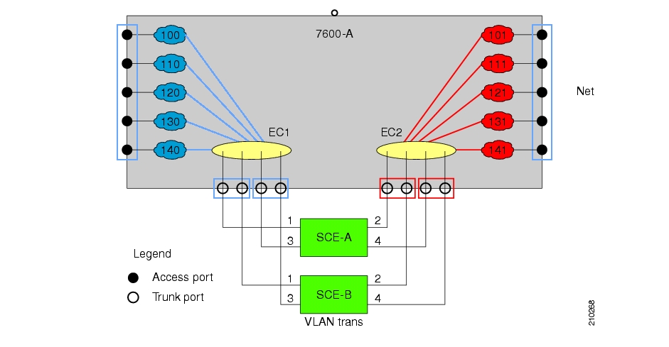
In this example, traffic enters the router via the access ports; it is forwarded to an EtherChannel, which is configured as a trunk, and enters the SCE 2000 platforms.
As can be seen from this drawing, the subscriber side VLAN tags must be different from those on the network side, or the router will simply forward the traffic to the opposite port. This can be supported very simply by having the SCE platform replace the VLAN tags according to a preset configuration.
Features
Configuration of an increment or decrement constant.
Configuration of the constant is global for the line card.
The configured operation (either increment or decrement) is applied to the network side.
The subscriber side automatically performs the opposite operation. That is, if the VLAN is incremented by X on the network side, it is decremented by X on the subscriber side.
VLAN tagged packets are changed (incremented or decremented) before transmission.
Non-tagged packet are not changed.
This feature allows seamless processing with non-VLAN traffic.
Limitations
LIC Bypass not supported – Translation is done in the transmission. Therefore, in LIC bypass, where there is no transmission, there is also no translation.
This means that in general, installations using the VLAN translation feature should rely on cutoff on failure and at upgrade (use redundant SCE platform).
STP hazard – VLAN translation may interfere with Spanning Tree Protocol. This should be taken in consideration when deploying the solution.
The maximum offset that can be configured is 2047. Note that there is no protection for wraparound.
Use this command to define the VLAN translation constant. Make sure that the same VLAN translation constant is configured for all SCE platforms in the system.
The following option is available:
value — Integer value by which the VLAN is to incremented or decremented.
The configured translation is applied to the network port side. The reverse operation is performed at the subscriber side.
For example, if "increment 5" is defined, at the network port the VLAN is incremented by 5, and at the subscriber port the VLAN is decremented by 5.
In this case, the network side VLAN tags might be 105, 205, 305, and the subscriber side the VLAN tags would then be 100, 200, 300.
Default = 0
Maximum = 2047 (Note that there is no protection for wraparound of the VLAN value.)
To define the VLAN translation constant, use the following command:
From the
SCE(config if)#prompt, typevlan translation increment|decrement valuevalueand press Enter.
Example:
The following example sets the translation constant to 10, decremented at the network side.
SCE(config if)#vlan translation decrement value 10Traffic rules and counters may be configured by the user. This functionality enables the user to define specific operations on the traffic flowing through the SCE Platform, such as blocking or ignoring certain flows or counting certain packets. The configuration of traffic rules and counters is independent of the application loaded by the SCE platform, and thus is preserved when the application being run by the SCE platform is changed.
Possible uses for traffic rules and counters include:
Enabling the user to count packets according to various criteria. Since the traffic counters are readable via the SCE SNMP MIB, these might be used to monitor up to 32 types of packets, according to the requirements of the installation.
Ignoring certain types of flows. When a traffic rules specifies an “ignore” action, packets matching the rule criteria will not open a new flow, but will pass through the SCE platform without being processed. This is useful when a particular type of traffic should be ignored by the SCE platform.
Possible examples include ignoring traffic from a certain IP range known to require no service, or traffic from a certain protocol.
Blocking certain types of flows. When a traffic rules specifies a “block” action, packets matching the rule criteria (and not belonging to an existing flow) will be dropped and not passed to the other interface. This is useful when a particular type of traffic should be blocked by the SCE platform.
Possible examples include performing ingress source address filtering (dropping packets originating from a subscriber port whose IP address does not belong to any defined subscriber-side subnet), or blocking specific ports.
It should be noted that using traffic rules and counters does not affect performance. It is possible to define the maximum number of both traffic rules and counters without causing any degradation in the SCE platform performance.
A traffic rule specifies that a defined action should be taken on packets processed by the SCE Platform that meet certain criteria. The maximum number of rules is 128, which includes not only traffic rules configured via the SCE platform CLI, but also any additional rules configured by external management systems, such as SCA BB. Each rule is given a name when it is defined, which is then used when referring to the rule.
Packets are selected according to user-defined criteria, which may be any combination of the following:
IP address — A single address or a subnet range can be specified for each of the line ports (Subscriber / Network).
Protocol — TCP/UCP/ICMP/IGRP/EIGRP/IS-IS/OSPF/Other
TCP/UDP Ports — A single port or a port range can be specified for each of the line ports (Subscriber / Network). Valid for the TCP/UDP protocols only.
TCP flags (TCP only).
Direction (Upstream/Downstream).
The possible actions are:
Count the packet by a specific traffic counter
Block the packet (do not pass it to the other side)
Ignore the packet (do not provide service for this packet — No bandwidth metering, transaction reporting etc. is done)
Quick-forward the packet with service — forward delay-sensitive packets through the fast path while maintaining serviceability for these packets
Quick-forward the packet with no service — forward delay-sensitive packets through the fast path with no service provided for these packets
Block and Ignore actions affect only packets that are not part of an existing flow.
Note that Block and Ignore are mutually exclusive. However, blocked or ignored packets can also be counted.
It is possible for a single packet to match more that one rule (The simplest way to cause this is to configure two identical rules with different names). When this happens, the system operates as follows:
Any counter counts a specific packet only once. This means that:
If two rules specify that the packet should be counted by the same counter, it is counted only once.
If two rules specify that the packet should be counted by different counters, it is counted twice, once by each counter.
Block takes precedence over Ignore — If one rule specifies Block, and another rule specifies Ignore, the packet is blocked.
Traffic counters count the traffic as specified by the traffic rules. The maximum number of counters is 32. Each counter is given a name when it is defined, which is then used when referring to the counter.
A traffic counter can be configured in one of two ways:
Count packets — the counter is incremented by 1 for each packet it counts.
Count bytes — the counter is incremented by the number of bytes in the packet for each packet it counts.
A traffic counter must be created before it can be referenced in a traffic rule. Use the following commands to create and delete traffic counters.
To create a traffic counter, use the following command:
From the
SCE(config if)#prompt, typetraffic-counter name<name> (count-bytes|count-packets)
Use the following commands to create and delete traffic rules.
To create a traffic rule, use the following command:
From the SCE(config if)# prompt, type
traffic-rule name<name>IP-addresses(all|(subscriber-side<IP specification> network-side <IP specification>))protocol<protocol>[tunnel-idtunnel-id specification] direction<direction>traffic-counter<traffic-counter>[action<action>]Where the command options are defined as follows:
IP specification:
all|([all-but] (<ip-address>|<ip-range>))<ip-address>is a single IP address in dotted-decimal notation, such as 10.1.2.3<ip-range>is an IP subnet range, in the dotted-decimal notation followed by the number of significant bits, such as 10.1.2.0/24.Use the
all-butkeyword to exclude the specified IP address or range of IP addresses
protocol:
Any one of the following protocols:
TCP/UCP/ICMP/IGRP/EIGRP/IS-IS/OSPF/Othertunnel id specification:
all|([all-but] tunnel id)tunnel id is an 8-bit Hex value range, in the format '(HEX)Tunnel-id' or '(HEX)MinTunnelId:(HEX)MaxTunnelId', which reflects the lower eight bits of the VLAN tag.
Tunnel ID based rules can only be used in "VLAN symmetric classify" mode, and only when tunnel id mode is enabled. Use the traffic-rule tunnel-id-mode command.
Note that the VLAN tag itself is a 12-bit value, and therefore aliasing of the lower 8 bits can occur, depending on the VLAN tags used
direction:
Any of the following:
upstream/downstream/bothtraffic-counter:
Either of the following:
name<name of an existing traffic counter> —Packets meeting the criteria of the rule are to be counted in the specified counter. If a counter name is defined, the “count” action is also defined implicitly. The keywordnamemust appear as well as the actual name of the counter.none—Ifnoneis specified, then an action must be explicitly defined via theactionoption.
action: (not required if the action is count only)
One of the following:
block— Block the specified trafficignore— Bypass the specified traffic; traffic receives no servicequick-forwarding— Forward delay-sensitive packets through the fast path while maintaining serviceability for these packetsquick-forwarding-ignore— Forward delay-sensitive packets through the fast path with no service provided for these packets
Example 1
This example creates the following traffic rule:
Name = rule1
IP addresses: subscriber side = all IP addresses, network side = 10.10.10.10 only
Protocol = other
Direction = both
Traffic counter = counter1
The only action performed will be counting
SCE (config if)#traffic-rule rule1 IP-addresses subscriber-side all network-side 10.10.10.10 protocol other direction both traffic-counter name counter1
Example 2
This example creates the following traffic rule:
Name = rule2
IP addresses: subscriber side = all IP addresses, network side = all IP addresses EXCEPT the subnet 10.10.10.0/24
Protocol = TCP
Tunnel id = all
Direction = downstream
Traffic counter = counter2
Action = Block
The actions performed will be counting and blocking
SCE (config if)#traffic-rule tunnel-id-mode (enables tunnel id mode)
SCE (config if)# traffic-rule rule2 IP-addresses subscriber-side all network-side all-but 10.10.10.0/24 protocol tcp tunnel-id all direction downstream traffic-counter name counter2 action blockExample 3
This example creates the following traffic rule:
Name = rule3
IP addresses: all
Protocol = IS-IS
Direction = upstream
Traffic counter = none
Action = ignore (required since traffic-counter = none)
The only action performed will be Ignore.
SCE (config if)#traffic-rule rule3 IP-addresses all protocol IS-IS direction upstream traffic-counter none action ignore
Use these commands to display existing traffic rule configuration, as well as traffic counter configuration (packets/bytes and the name of the rule using the counter) and traffic counter value. You can also reset a specific counter or all counters.
To view a specified traffic rule, use the following command:
From the
SCE#prompt, typeshow interface linecard 0 traffic-rulename<rule-name>
To view all existing traffic rules, use the following command:
From the <
product>#prompt, typeshow interface linecard 0 traffic-rule all
To view a specified traffic counter, use the following command:
From the
SCE#prompt, typeshow interface linecard 0 traffic-counter name<counter-name>
Example
The following example displays information for the traffic counter “cnt”.
SCE# show interface linecard 0 traffic-counter name cnt
Counter 'cnt' value: 0 packets. Rules using it: None.
To view all existing traffic counters, use the following command:
From the <
product>#prompt, typeshow interface linecard 0 traffic-counter all
Example
The following example displays information for all existing traffic counters.
SCE#show interface linecard 0 traffic-counter all

Counter 'cnt' value: 0 packets. Rules using it: None.
1 counters listed out of 32 available.The SCE platform TOS marking feature enables marking the TOS field in the IP header of each packet according to two applicative attributes of the packet: its Class (class of service) and its Color (reflects the packet’s level of compliance to its relevant bandwidth limitations, where applicable). The actual TOS value set in the IP header is determined according to the configurable TOS table, based on the Class and Color. The default values in the TOS table are based on the Diffserv standard.
Note
The first few TCP packets (connection establishment) are associated and marked with a default AF4 class that is mapped to the AF-4 queue and are marked accordingly. This occurs because the SCE platform transmits the first few packets before classifying the flow and identifying the application or service.
The following commands are relevant to TOS marking:
no tos-marking diffserv
tos-marking mode
tos-marking set-table-entry class
tos-marking reset-table
show interface LineCard tos-marking mode
show interface LineCard tos-marking tableTo modify the TOS table, use the following command:
From the
SCE(config if)#prompt, typetos-marking set-table-entryclasscolorcolorvaluevalueand press Enter.classis the applicative class of the packet (BE, AF1, AF2, AF3, AF4, EF),,coloris the applicative color (green, red or any) andvalueis the value to be assigned to the packet (value set to the IP TOS field). Thevalueparameter must be in hexadecimal format in the range0x0to0x3f.
Example:
The following example sets a TOS marking table entry.
SCE (config if)#tos-marking set-table-entry class AF3 color green value 0x24By default, the SCE platform hardware drops red packets (packets that are marked to be dropped due to BW control criteria). However, this presents a problem for the user who needs to know the number of dropped packets per service. In order to be able to count dropped packets per service, the traffic processor must see all dropped packets for all flows. However, if the hardware is dropping red packets, the traffic processor will not be able to count all dropped packets and the user will not get proper values on the relevant MIB counters
The user can disable the drop-red-packets-by-hardware mode. This allows the application to access existing per-flow counters. The application can then retrieve the number of dropped packets for every flow and provide the user with better visibility into the exact number of dropped packets and their distribution.
Note that counting all dropped packets has a considerable effect on system performance, and therefore, by default, the drop-red-packets-by-hardware mode is enabled.
Use this command to disable the drop-red-packets-by-hardware mode, enabling the software to count all dropped packets.
By default hardware packet drop is enabled.
Note
Disabling this feature may have both delay and performance implications.
The connection mode command allows you to configure the topology of the system in one command. The connection mode is determined by the physical installation of the SCE platform.
There are four topology-related parameters included in the connection mode command:
Connection mode — Can be any one of the following, depending on the physical installation of the SCE platform:
Inline — single SCE platform inline
Receive-only — single SCE platform receive-only
Inline-cascade — two cascaded SCE platforms inline
Receive-only-cascade — two cascaded SCE platforms receive-only
Default — inline
Physically-connected-links — In cascaded topologies, defines which link is connected to this SCE platform. Possible values are ‘link-0’ and ‘link-1’.
Not applicable to single SCE platform topologies.
Priority — This parameter defines which is the primary SCE platform. It is applicable only in a two SCE platform topology. Possible values are ‘primary’ and ‘secondary’
Not applicable to single SCE platform topologies.
On-failure — This parameter determines whether the system cuts the traffic or bypasses it when the SCE platform either has failed or is booting.
Default — bypass
Not applicable to receive-only topologies.
Note
Do not change the connection mode unless the physical installation has been changed.
To define the system topology, use the following command:
From the
SCE (config if)#prompt, typeconnection-modeinline|receive-only|inline-cascade|receive-only-cascadephysically-connected-links [link 0|link 1] priority [primary|secondary] on-failure [bypass|cutoff]and press Enter.
Example 1:
The following example defines the primary device in a two-SCE platform redundant, inline topology. Link 0 is connected to this device, and the link mode on failure is bypass
SCE (config if)# connection-mode inline-cascade physically-connected-links link-0 priority primary on-failure bypass
Example 2:
The following example defines a single-SCE platform, dual link, receive-only topology. Neither link mode on failure, nor physically-connected-links, nor priority is applicable.
SCE (config if)# connection-mode receive-only
To display the current configuration of the SCE platform link connection, use the following command:
From the
SCE>prompt, typeshow interface linecard 0 connection-mode.
Example:
The following example shows how to display the current configuration of the connection mode.
SCE>show interface LineCard 0 connection-mode
Connection mode is inline
slot failure mode is bypass
Redundancy status is standalone
SCE>
The SCE platform has an internal hardware card used to maintain the links even when the SCE platform fails. This hardware card has four possible modes of operation:
bypass
forwarding
cutoff
sniffing
Normally, the link mode is selected by the SCE platform software according to the configured connection-mode. However, the link-mode command can be used to enforce a specific desired mode. This may be useful when debugging the network, or in cases where we would like the SCE platform just to forward the traffic. (Note that this is only relevant to inline topologies even though the configuration is available also when in receive-only mode.)
The following link mode options are available:
Forwarding — forwards traffic on the specified link to the SCE platform for processing.
Bypass — stops all forwarding of traffic on the specified link to the SCE platform. Traffic still flows on the link, but is not processed in any way by the SCE platform.
This does not affect the redundancy states.
Sniffing — allows the SCE platform to forward traffic on the specified link through the bypass mechanism while still analyzing the traffic passively.
Sniffing is permitted to be configured for all links, only (use the all-links option).
Cutoff — completely cuts off flow of traffic through the specified link.
Note the following recommendations and restrictions:
Since the SCE 1000 platform has only one link, the link is not specified.
Since the SCE 2000 platforms have more than one link, it is required to specify the link. The link designations are different for the GBE and FE platforms, as follows:
SCE 2000 4xGBE — GBE1-GBE2/GBE3-GBE4
SCE 2000 4/8xFE — LINK1/LINK2
Use the
'all-links'option to configure the link mode for all links (SCE 2000 platforms only).It is recommended that both links be configured together. Use the all-links option.
Link mode is relevant only to inline topologies.
It is recommended that in cascaded topologies, both SCE platforms be configured for the same link mode, otherwise the service will be unpredictable.
Sniffing can only be configured for all links, therefore, to configure sniffing, the all-links option is required, not just recommended.
The default link mode is forwarding. When other link modes are selected, active service control is not available and any service control configuration will not be applicable.
Use the following commands to force a virtual failure condition, and to exit from the failure condition when performing an application upgrade. (See Application Upgrade.)
The failure-recovery operation-mode command defines the behavior of the system after boot resulting from failure. The system may return to operational mode, or remain not operational.
The default value is operational.
To edit the failure recovery operational mode, use the following command:
From the
SCE(config)#prompt, typefailure-recovery operation-mode operational|non-operationaland press Enter.Enter either the value
operationalornon-operational.
Example 1:
The following example sets the system to boot as non-operational after a failure
SCE(config)#failure-recovery operation-mode non-operational
SCE(config)#
Example 2:
The following example sets the system to the default failure recovery mode.
SCE(config)# default failure-recovery operation-mode
SCE(config)#The user can configure the behavior of the SCE platform in case of failure of the Subscriber Manager (SM):
If SM functionality is critical to the operation of the system — configure the desired behavior of the SCE platform in the event of any loss of connection with the SM (may be due either to failure of the SM or failure of the connection itself).
If SM functionality is not critical to the operation of the system — no action needs to be configured.
The following options are available :
force-failure¾Force failure of SCE platform. The SCE platform then acts according to the behavior configured for the failure state.remove-mappings¾Remove all current subscriber mappings.shut¾The SCE platform shuts down and quits providing service.none (default)¾Take no action.
To configure the behavior of the SCE platform in case of failure of the SM, use the following command:
From the SCE(config if)# prompt, type
subscriber sm-connection-failure action [force-failure|none|remove-mappings|shut]and press Enter.
You can also configure the timeout interval; the length of time that the SM-SCE platform connection is disrupted before a failed connection is recognized and the configured behavior is applied.
In some topologies, link failure on one port must be reflected to the related port in order to allow the higher layer redundancy protocol in the network to detect the failure and function correctly. The link failure-reflection command determines the behavior of the system when there is a link problem.
The link failure-reflection command enables reflection of a link failure. Use the [no] form of this command to disable failure reflection on the link.
The default value is disabled.
To enable reflection of link failure, use the following command:
From the
SCE(config if)#prompt, typelink failure-reflectionand press Enter.
To disable reflection of link failure, use the following command:
From the
SCE(config if)#prompt, typenolink failure-reflectionand press Enter.
The Link reflection on all ports feature extends the link failure reflection feature. It allows the user to determine whether all ports should be taken down if a single port link fails.
In certain topologies, when a failure state occurs on one link, the link state must be reflected to all ports in order to signal any element using this SCE platform that the device is in a failure state, and therefore cannot be used.
Note
The Link reflection on all ports feature cannot be used in a cascade mode, because in this mode one of the links is used to provide redundancy.
In link reflection on all ports mode, all ports of the SCE platform are forced down and the link state of the first port is reflected on all the ports.
When recovering from the failure state, the forced down ports (the other link) are brought up only after the first failed port (link) has recovered. In addition, the reflection algorithm will not try to reflect failure for this link again for the next 15 seconds, to avoid link stability problems on auto-negotiation.
The on-all-ports keyword enables reflection of a link failure to all ports. Use the [no] form of this command to disable failure reflection to all ports (the on-all-ports keyword is not used in the [no] form of the command).
The default value is disabled.
The linecard-aware-mode option is an additional extension of the link failure reflection feature for use in MGSCP topologies. Use this option when the subscriber-side interface and the corresponding network-side interface of the same link of the SCE 2000 platform are connected to the same linecard in the router.
This mode reflects a failure of one port to the other three ports of the SCE 2000 differently, depending on different failure conditions, as follows:
One interface of the SCE 2000 is down: Link failure is reflected to the all other SCE platform ports.
Two reciprocal ports of the SCE 2000 are down simultaneously, indicating a possible problem in the linecard of the router to which the SCE platform is connected: In this case the failure is not reflected to any of the other interfaces. This allows the second link in the SCE platform to continue functioning without interruption.
Use the [no] form of this command with the linecard-aware-mode keyword to disable the linecard aware mode without disabling link failure reflection itself.
The RDR formatter is used to gather the streams of events passed from the application, format the data into Raw Data Records (RDRs), and send these RDRs to the appropriate destination(s).
There can be a maximum of eight destinations for the RDRs. The system decides which destination to send the RDRs to on the basis of three factors:
Categories — RDRs may be divided into four categories, with each category being assigned to a maximum of three of the defined destinations. A destination may be assigned to more than one category.
Priority — The priority value assigned to the destination for a specific category
Forwarding mode — the pattern in which the RDR traffic is divided between the various destinations
The SCE platform can be configured with a maximum of eight RDR destinations, three destinations per category. Each destination is defined by its IP address and TCP port number, and is assigned a priority for each category to which it is assigned.
The following figure illustrates the simplest RDR formatter topology, with only one category and one destination.
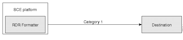
The following figure illustrates a complex topology using both categories and four destinations. Each category can send RDRs to three of the four destinations.
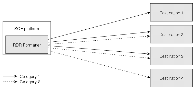
In certain installations, RDRs must be sent to different collector servers according to their type. For instance, in the pre-paid environment, some RDRs must be sent to the pre-paid collector to get a new quota, while others should be sent to the mediation system. In this case, the RDRs are divided into up to four groups, and each group, or category, is assigned to a particular destination or destinations. The categories are defined by the application running on the SCE platform.
The system supports up to four categories. Therefore, the RDR formatter destinations must be configured regarding each category in use. Each destination may be assigned to more than one category and may be assigned the same or different priorities for each category. If more than one destination is defined for a category, a load-balancing or multicast forwarding mode could be selected. (Obviously, these modes have no meaning if there is only one destination per category.)
It is also possible to remove a category from a destination, leaving only the desired category. If all categories are removed, the destination itself is deleted.
By default, the categories are referred to as Category 1 through Category 4. However, the user may define meaningful names for the categories. This generally reduces confusion and prevents errors.
The priority value is used to indicate whether the destination should be a destination for a given category. A high priority indicates that RDRs from a category should be sent to a particular destination. A low priority indicates that RDRs from a category should not be sent to a particular destination.
Priority is related to the redundant forwarding mode, in that it indicates which is the primary active connection. Priority values have no effect in multicast forwarding mode.
Each destination is assigned a priority value for each category. The first destination that is configured is automatically assigned a priority of 100 (highest priority) for all categories, unless explicitly defined otherwise.
Following are some important points to keep in mind regarding priority values:
Two destinations may not have the same priority for one category. The priority values for destinations within a category must be unique in order to have any meaning.
If only one priority value is assigned to the destination, that priority is automatically assigned to all categories for that destination.
If only one category is assigned a priority value for a destination, no RDRs from the other categories will be sent to the specified destination.
Assign a high priority if RDRs from the specified category should be sent to this destination. Assign a low priority if RDRs from the specified category should less likely to be sent to this destination.
Redundant forwarding mode — Assign a high priority to the primary destination for the system/category. Assign a lower priority to the secondary destination for the system/category.
When more than one RDR destination is defined for a category, the system must decide which of these destinations is to receive the RDRs. This is determined by the forwarding mode. There are two forwarding modes:
Redundancy — All RDRs are sent only to the primary (active) connection. If the primary connection fails, the RDRs will be sent to the connected destination with the next highest priority.
Multicast — All RDRs are sent to all destinations. This feature may negatively affect performance in an installation with a high rate of RDRs.
The following commands are relevant to the RDR-formatter:
RDR-formatter forwarding-mode
service RDR-formatter
no service RDR-formatter
RDR-formatter destinations:
RDR-formatter destination
no RDR-formatter destination
no RDR-formatter destination all
RDR-formatter categories:RDR-formatter category-number
no RDR-formatter category-number
Note
Note the following configuration restrictions:
• The protocol version must be RDRv1 (default value)
• The simple-load-balancing forwarding mode is not currently supported
• The size of the history buffer must be zero bytes (the default value). Other values may cause duplication of RDRs.
• The connection timeout parameter is not currently supported.
To configure the RDR Formatter forwarding mode, use the following command:
From the SCE(config)# prompt, type RDR-Formatter forwarding-mode <redundancy>|<multicast>, and press Enter.
The specified RDR Formatter forwarding mode is defined.
Example:
The following example shows how to set the RDR Formatter forwarding-mode to multicast
SCE(config)# RDR-Formatter forwarding-mode multicastIn order for the RDRs from the SCE platform to arrive at the correct location, the IP address of the destination and its TCP port number must be configured.
A priority value must be assigned. Priority is important in the redundancy forwarding mode, but not crucial in simple-load-balancing mode or multicast mode. Remember that in load-balancing and multicast modes, the existence of any priority value causes the destination to receive RDRs.
The relationship between priorities and categories is addressed in the next section.
To configure an RDR Formatter destination (all categories), use the following command:
From the SCE(config)# prompt, type RDR-Formatter destination <IP address> port <port-number> [priority <priority(1-100)>], and press Enter.
The RDR Formatter destination is defined. When no category is specified, as in the above example, the specified priority is assigned to all categories.
Example:
The following example shows how to configure two RDR Formatter destinations in a system without using the categories.
The first destination will automatically be assigned a priority of 100, and therefore the priority does not need to be explicitly defined. For the second destination, the priority must be explicitly defined.
The same priority will automatically be assigned to both categories for each destination, but since the categories will be ignored, this is irrelevant.
SCE(config)# RDR-Formatter destination 10.1.1.205 port 33000
SCE(config)# RDR-Formatter destination 10.1.1.206 port 33000 priority 80
There are two steps in defining the RDR formatter destination categories:
Define the category names (optional).
Assign the destinations to both categories.
Configuring the destinations with the proper priorities for each category, as well as configuring all the other RDR formatter parameters, may be approached in several different ways, and may take some planning. Refer to the examples below for illustrations of some of the issues involved in configuring categories.
To configure an RDR Formatter category name, use the following command:
From the SCE(config)# prompt, type RDR-Formatter category-number 1-4 name <category-name>, and press Enter.
The name for the specified category number is defined. This category name can then be used in any RDR-formatter command instead of the category number.
To configure a RDR Formatter destination and assign it to a category, use the following command:
From the SCE(config)# prompt, type RDR-Formatter destination <IP address> port <port-number> category [name <category-name> |number [1-4]] [priority <priority(1-100)>] [category [name <category-name> |number [1-4]] [priority <priority(1-100)>]], and press Enter.
The RDR Formatter destination is defined. A different priority may be assigned to each category. (This can be done in one command for a maximum of two categories.) If RDRs from the specified category should be sent to this destination, the priority for the category should be high. If the RDRs from the specified category should not be sent to this destination, the priority should be low.
Note that within each category the priorities must be unique for each destination.
Example 1:
The following example defines a name for one category, and then configures two RDR Formatter destinations, assigning each to a different category (see diagram).
The RDRs of category 1 are to go to the first destination, so a high priority was assigned to that category in the first destination, and no priority in the second.
Since all RDRs in category 2 (prepaid) are to go to the second destination, the priority assigned to category 2 is assigned only to the second destination and not to the first.
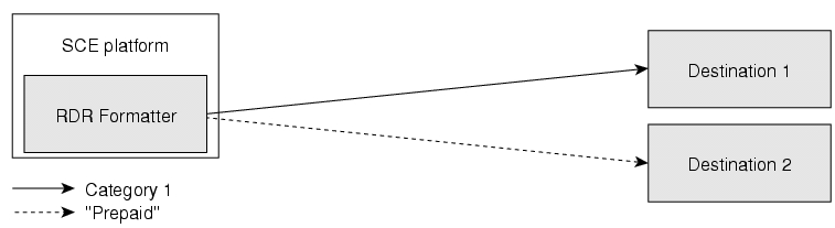
Note that if there is a loss of connection to either destination, transmission of RDRs of the relevant category is interrupted until the connection is re-established. There is no redundant connection defined for either category.
SCE(config)# RDR-Formatter category-number 2 name prepaid
SCE(config)# RDR-Formatter destination 10.1.1.205 port 33000 category number 1 priority 90
SCE(config)# RDR-Formatter destination 10.1.1.206 port 33000 category name prepaid priority 80Example 2:
This example is similar to the above, but a low priority is assigned to the second category for each destination, rather than no priority. This allows each destination to function as a backup for the other in case of a problem with one of the connections (redundancy forwarding mode).
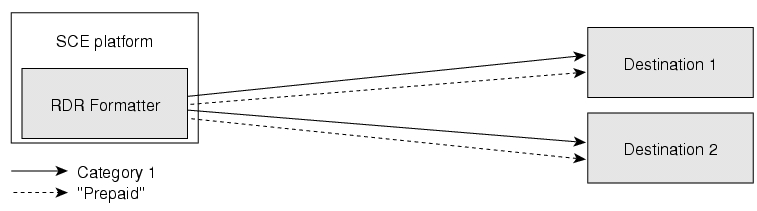
SCE(config)# RDR-Formatter category-number 2 name prepaid
SCE(config)# RDR-Formatter destination 10.1.1.205 port 33000 category name prepaid priority 90 category number 1 priority 25
SCE(config)# RDR-Formatter destination 10.1.1.206 port 33000 category number 1 priority 80 category name prepaid priority 20Example 3:
This example demonstrates two methods for assigning one category to the first destination only, while the other category uses the second destination as the primary destination, and the first destination as a secondary destination.
SCE(config)# RDR-Formatter category-number 2 name prepaid
SCE(config)# RDR-Formatter destination 10.1.1.205 port 33000 category name prepaid priority 90 category number 1 priority 10
SCE(config)# RDR-Formatter destination 10.1.1.206 port 33000 category number 1 priority 95In the following example, all priority values seem quite high. However, it is the relative values of priorities for a category that determine which destination is the primary destination.
SCE(config)# RDR-Formatter category-number 2 name prepaid
SCE(config)# RDR-Formatter destination 10.1.1.205 port 33000 priority 90
SCE(config)# RDR-Formatter destination 10.1.1.206 port 33000 priority 95
SCE(config)# no RDR-Formatter destination 10.1.1.206 port 33000 category name prepaidExample 4:
Finally, the following illustrates a more complex configuration with one category (prepaid) assigned to one destination and the other (billing) being sent to both destinations, in multi-cast mode.
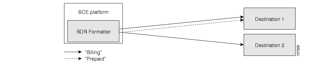
The forwarding mode is defined for the entire RDR formatter, not just one category. Since the category “prepaid” goes to only one destination, the forwarding mode is irrelevant. It is relevant, however to the “billing” category, since it goes to two different destinations.
SCE(config)# RDR-Formatter forwarding-mode multi-cast
SCE(config)# RDR-Formatter category-number 1 name billing
SCE(config)# RDR-Formatter category-number 2 name prepaid
SCE(config)# RDR-Formatter destination 10.1.1.205 port 33000 priority 40
SCE(config)# no RDR-Formatter destination 10.1.1.205 port 33000 category name prepaid
SCE(config)# RDR-Formatter destination 10.10.10.96 port 33000 category name billing priority 90
SCE(config)# RDR-Formatter destination 10.1.96.0 port 33000 category name prepaid priority 80Dynamic configuration of RDRs to multiple categories is supported.
Each RDR tag has a list of categories. The default category is the one that was assigned when application was loaded.
The configuration of categories to RDR tags is done by adding and removing mappings. A user can add a mapping of RDR tag to a category and remove a mapping, including the default mapping. If only one category is left configured for a certain tag, it cannot be removed.
The user must provide the RDR tag ID and the category number to add or remove. The configuration is saved as part of the application configuration.
Use these command to add or remove a mapping.
The following options are available:
tag-ID — The complete 32 bit value given as an hexadecimal number. The RDR tag must be already configured in the Formatter by the application.
category-number — Number of the category (1-4) to which to map the RDR tag.
To add a mapping to a category, use the following command:
From the
SCE(config)#prompt, typeRDR-formatter rdr-mapping (tag-ID<tag number>category-number<category number>) and press Enter.If the table already contains a mapping with the same tag and category number, an error is issued and nothing is done.
The system can display the complete RDR formatter configuration, or just specific parameters.
The following commands can be used to display the RDR formatter configuration and statistics:
show RDR-formatter
show RDR-formatter connection-status
show RDR-formatter counters
show RDR-formatter destination
show RDR-formatter enabled
show RDR-formatter forwarding-mode
Show RDR-formatter rdr-mapping
show RDR-formatter statistics
To display the current RDR formatter configuration, use the following command:
From the
SCE>prompt, typeshow RDR formatter.
Example:
The following example shows how to display the current RDR formatter configuration.
SCE#show RDR-formatter
Status: enabled
Connection is: up
Forwarding mode: redundancy
Connection table:
-------------------------------------------------------------------------|
Collector   | Port|Status|           Priority per Category:              |
IP Addres / |     |      |-----------------------------------------------|
Host-Name   |     |      |Category1  |Category2  |Category3  |Category4  |
-------------------------------------------------------------------------|
10.1.1.205  |33000|Up    |100 primary|100 primary|100 primary|100 primary|
10.1.1.206  |33000|Down  |60         |60         |60         |60         |
10.12.12.12 |33000|Up    |40         |40         |40         |40         |
-------------------------------------------------------------------------|

RDR:    queued:         0 ,sent:         0, thrown:         0
UM:     queued:         0 ,sent:         0, thrown:         0
Logger: queued:         0 ,sent:         0, thrown:         0
Errors: thrown:         0
Last time these counters were cleared: 14:05:57 UTC SUN February 23 2003
SCE#
Refer to CLI Command Reference for a complete description of the other show RDR-formatter commands.
The silent command disables the LineCard from issuing Raw Data Records (RDR). Use the [no] form of this command if you want the LineCard to send reports.
To disable the LineCard from sending Raw Data Records (RDRs), complete the following steps:
From the
SCE(config)#prompt, typeinterface Linecard 0, and press Enter.The
SCE(config if)#prompt appears.Type
silent, and press Enter.The LineCard stops producing RDRs and the
SCE(config if)#prompt appears.
The SCE platform is subscriber aware, that is, it can relate traffic and usage to specific customers. This ability to map between IP flows and a specific subscriber allows the system to do the following:
Maintain the state of each subscriber transmitting traffic through the platform
Provide usage information for specific subscribers
Enforce the appropriate policy on subscriber traffic (each subscriber can have a different policy)
In the Service Control solution, a subscriber is defined as a managed entity on the subscriber side of the SCE Platform to which accounting and policy are applied individually.
The following table lists several examples of subscribers in Service Control solutions.
Table 9.1. Subscriber Examples
|
The Subscriber |
Subscriber Characteristics | |
|---|---|---|
|
|
Managed Entity |
Subscriber (Entity) Identified By |
|
DSL residential subscriber |
DSL residential user |
IP address The list of IP addresses is allocated by a Radius server |
|
Cable residential subscriber |
Cable residential user |
IP address The list of IP addresses of the CPEs is allocated dynamically by a DHCP server |
|
Owner of a 3G-phone that is subscribed to data services |
3G-phone owner |
The MS-ISDN, which is dynamically allocated by a Radius server. |
|
A corporate/enterprise customer of the service provider |
The corporate/enterprise and the traffic it produces |
The set of NAT-ed IP addresses, which are allocated statically |
|
A CMTS |
The CMTS and the broadband traffic of the Cable Modem users that connect to the Internet through the CMTS |
|
|
A VPN |
MPLS/VPN subscriber |
All traffic of that VPN customer, which is aggregated into a single VPN subscriber |
|
SCMP subscriber |
SCMP subscriber |
|
Mapping IP traffic flows to subscribers enables the SCE platform to enforce policies on these flows based on the subscriber who produced them.
The SCE platform can also insert the information that identifies the subscriber into the RDR records that it produces for analyzed traffic, facilitating OSS systems that use these data records for billing and analysis purposes.
The SCE platform includes dedicated infrastructure for per-subscriber BW shaping, IP traffic quota management, or any other per-subscriber long-term state management. This is implemented using a set of dedicated data structures that are dynamically managed in the SCE platform per subscriber.
The SCE platform examines each IP flow and maps it to the subscriber that produced the flow using one or more networking parameters of this flow. Examples of these could be:
Source IP address
Group of source IP addresses
Range of source IP addresses
VLAN tag
MPLS labels
SCE subscriber ID assigned by SCMP
These parameters are sometimes referred to as Network-ID. In order to perform the mapping between the Network-ID and Subscriber-ID, the SCE platform must be configured with this mapping information.
In some cases the subscriber’s Network-ID is static and changes only rarely and at long intervals. In such cases, obtaining the mapping information is quite simple, and can be implemented by importing the content of a text file, or even by typing the information via the user interface. In other cases, the Network-ID has a dynamic nature, and tends to change every time the subscriber logs into the network. In this case the SCE platform must obtain the mapping information from some element that stores this information.
The most common Network-IDs are IP addresses. Typically, obtaining the mappings between subscriber-IDs and IP addresses is done through integration with an AAA element or a subscriber repository.
Many times, the SCE platform runs a Service Control Application that is policy-driven, so it should also be provisioned with the parameters of the policy that should be applied to each of the subscribers. In simple cases, there is only a small set of standard policy packages (Gold, Silver, Bronze…) so the per subscriber information includes only an index into the policies list. In other cases, a whole set of policy parameters should be configured per subscriber. Often the policy that should be applied per subscriber is managed using the same AAA infrastructure that is used for managing the Subscriber-ID to Network-ID mappings.
There are two methods of managing subscribers:
Subscriber Manager (SM) component — usually necessary in topologies where full dynamic subscriber integration is required (see the Cisco SCMS Subscriber Manager User Guide for details).
CLI commands — can be used to import and export subscriber information, as well as to monitor subscribers.
Note
The Subscriber Manager is required for an MPLS/VPN network.
As is described in the following sections, subscriber-related information can be imported from external files. This provides an easy method for transferring large quantities of subscriber information to and from the SCE platform.
Service Control solutions support several modes of handling subscribers:
Subscriber-less mode
Anonymous subscriber mode
Static subscriber aware mode
Dynamic subscriber aware mode
Note that not all the Service Control solutions support all modes.
The most basic mode is Subscriber-less mode. In this mode, there is no notion of subscriber in the system, and the entire link where the SCE platform is deployed is treated as a single subscriber. Global Application level analysis (such as total p2p, browsing) can be conducted, as well as global control (such as limiting total p2p to a specified percentage). From a configuration stand point, this is a turnkey system and there is no need to integrate or configure the system from a subscriber perspective.
In Anonymous subscriber mode, analysis is performed on an incoming network ID (IP address, VLAN or MPLS/VPN ID), as the SCE platform creates an 'anonymous/on-the-fly' record for each subscriber. This permits analyzing traffic at an individual network ID level (for example, to identify/monitor what a particular 'subscriber' IP is currently doing) as well as control at this level (for example, to limit each subscriber's bandwidth to a specified amount, or block, or redirect). Anonymous-subscriber allows quick visibility into application and protocol usage without OSS integration, and permits the application of a uniform control scheme using predefined templates.
There are two possible Subscriber Aware modes. In these modes, subscriber IDs and currently used network IDs are provisioned into the SCE platform. The SCE platform can then bind usage to a particular subscriber, and enforce per-subscriber policies on the traffic. Named reports are supported (such as top subscribers with the OSS IDs), quota-tracking (such as tracking a subscriber-quota over time even when network IDs change) as well as dynamic binding of packages to subscribers. The two Subscriber Aware modes are:
Static subscriber aware — The network IDs are static. The system supports the definition of static-subscribers directly to the SCE platform. This is achieved by using the SCE platform CLI, and defining the list of subscribers, their network IDs and policy information using interactive configuration or import/export operations.
Dynamic subscriber aware — The network IDs change dynamically for each subscriber login into the Service Provider’s network. In this case, subscriber awareness is achieved by integrating with external provisioning systems (either directly or through the SM) in order to dynamically learn network-ID to subscriber mappings, and distribute them to the SCE platforms.
MPLS/VPN subscribers are supported only in the dynamic subscriber aware mode. The system must dynamically map the internal MPLS label and the MAC address of the PE to the correct VPN subscriber.
Subscribers can be aged automatically by the SCE platform. ‘Aging’ is the automatic removal of a subscriber, performed when no traffic sessions assigned to it have been detected for a certain amount of time. The most common usage for aging is for anonymous subscribers, since this is the easiest way to ensure that anonymous subscribers that have logged-out of the network are removed from the SCE platform and are no longer occupying resources. Aging time can be configured individually for introduced subscribers and for anonymous subscribers.
An anonymous group is a specified IP range, possibly assigned a subscriber template. When an anonymous group is configured, the SCE platform generates anonymous subscribers for that group when it detects traffic with an IP address that is in the specified IP range. If a subscriber template has been assigned to the group, the anonymous subscribers generated have properties as defined by that template. If no subscriber template has been assigned, the default template is used.
Subscriber templates are identified by a number from 0-199. Subscriber templates 1-199 are defined in csv formatted subscriber template files. However, template #0 cannot change; it always contains the default values.
If an anonymous group is not explicitly assigned a template, the group uses template #0.
Note
MPLS/VPN subscribers cannot be defined, imported, or exported by means of a subscriber file.
Individual subscribers, anonymous groups, and subscriber templates may all be defined in csv files. A csv file is a text file in a comma-separated-values format. Microsoft Excel™ can be used to view and create such files. The subscriber data is imported into the system using the appropriate CLI command. The SCE platform can also export the currently configured subscribers, subscriber templates and anonymous groups to csv-formatted files
Subscriber csv files and subscriber template csv files are application-specific. Refer to the relevant application documentation for the definition of the file format.
Each line in a csv file should contain either a comment (beginning with the character ‘#’), or a list of comma-separated fields.
Subscriber csv files are application-specific, but a default format is defined by the SCE, which is used when the application does not choose to over-ride it. The application might over-ride the format when additional data is desired for each subscriber or subscriber template. Refer to the relevant Service Control Application documentation to see if the application defines a different format.
Subscriber template csv files are application-specific. Refer to the relevant Service Control Application documentation of the file format.
Anonymous groups csv files are not application specific. Their format is described below.
Each line has the following structure:
name, mappings, packageId
Name — is the subscriber name
Mappings — contains one or more mappings, specifying the Tunnel IDs or IP addresses mapped to this subscriber. Multiple mappings are separated by semi-colon. Tunnel IDs and IP address/range cannot be specified for the same subscriber. The following mapping formats are supported:
Tunnel ID — A number in the range 0-1023. Example: 4
Note
Currently only VLAN IDs are supported.
Tunnel ID range — A range of tunnel Ids. Example: 4-8
IP address — in dotted decimal notation. Example: 10.3.4.5
IP address range — dotted decimal, followed by the amount of significant bits. Note that the non-significant bits (As determined by the mask) must be set to zero. Example: 10.3.0.0/16. Example for a bad range: 10.1.1.1/24 (Should be 10.1.1.0/24).
packageId: the ID of the package to which the subscriber is assigned
Here is an example for a subscriber csv file in the default format:
# A comment line
sub7, 10.1.7.0/24, 1
sub8, 10.1.12.32, 1
sub9, 5, 2
sub10, 13-17, 2
sub11, 39;41, 1
sub12, 10.1.11.90; 10.3.0.0/16, 2Each line has the following structure:
name, IP-range, template-index, manager-name(optional)
Name — is the anonymous group name
IP-range — dotted decimal, followed by the amount of significant bits. Example: 10.3.0.0/16
Template-index — is the index of the subscriber template to be used by subscribers belonging to this anonymous group.
Manager-name (optional) — is either SM or the name of the SCMP peer. Use "SM" to pull subscribers from the SM (if it exists). If not specified, "SM" is assumed.
Here is an example for an anonymous groups csv file:
# Yet another comment line
anon1, 10.1.1.0/24, 1, SCMP1
anon2, 10.1.2.0/24, 2, SCMP2
anon3, 10.1.3.0/32, 3, SCMP3
anon4, 10.1.4.0/24, 3, SCMP3
anon5, 10.1.5.0/31, 2, SM
anon6, 10.1.6.0/30, 1, SM
anon7, 0.0.0.0/0, 1, SMUse the following commands to import subscriber data from csv files and to export subscriber data to these files:
subscriber import csv-file
subscriber export csv-file
subscriber anonymous-group import csv-file
subscriber anonymous-group export csv-file
subscriber template import csv-file
subscriber template export csv-file
These subscriber management commands are LineCard interface commands. Make sure that you are in LineCard Interface command mode, (see Entering LineCard Interface Configuration Mode).
Note
MPLS/VPN subscribers cannot be defined, imported, or exported by means of a subscriber file.
To import subscribers from the csv subscriber file, use the following command:
From the
SCE(config if)#prompt, typesubscriber import csv-file filename and press Enter.The subscriber information is imported from the specified file.
Imported subscriber information is added to the existing subscriber information. It does not overwrite the existing data.
If the information in the imported file is not valid, the command will fail during the verification process before it is actually applied.
Use the following commands to remove all subscribers, anonymous groups, or subscriber templates from the system.
no subscriber all
no subscriber anonymous-group all
clear subscriber anonymous
default subscriber template all
Use the following commands to remove a specific subscriber or anonymous group from the system.
no subscriber name
no subscriber anonymous-group name
These subscriber management commands are LineCard interface commands (with the exception of the clear subscriber anonymous command, which is a Privileged Exec command). Make sure that you are in LineCard Interface command mode, (Entering LineCard Interface Configuration Mode and that the SCE(config if)# prompt appears in the command line.
To remove a specific subscriber, use the following command:
From the
SCE(config if)#prompt, typenosubscriber namesubscriber-nameand press Enter.
To remove all introduced subscribers, use the following command:
From the
SCE(config if)#prompt, typenosubscriber alland press Enter.
To remove a specific anonymous subscriber group, use the following command:
From the
SCE(config if)#prompt, typenosubscriber anonymous-group namegroup-nameand press Enter.
To remove all anonymous subscriber groups, use the following command:
From the
SCE(config if)#prompt, typenosubscriber anonymous-group alland press Enter.
To remove all anonymous subscribers, use the following command:
From the
SCE#prompt, typeclearinterface linecard 0subscriber anonymous alland press Enter.
Note
The clear subscriber anonymous command is a Privileged Exec command.
To remove all subscriber templates, use the following command:
From the
SCE(config if)#prompt, typedefaultsubscriber template alland press Enter.All subscriber templates are removed from the system. All anonymous subscribers will be assigned to the default subscriber template.
All subscribers with tunnel mappings must be cleared in order to change the tunneling mode. If there are subscribers that have either MPLS/VPN or VLAN mappings, and the SM cannot remove them for some reason (for example, if there is no communication between the SM and the SCE platform), use this command.
This command allows you to switch out of MPLS/VPN mode without reload when the SM is down.
Note
Usethis command ONLY when the SCE platform is disconnected from the SM.
To create anonymous groups by importing anonymous subscribers from the csv file, use the following command:
From the
SCE(config if)#prompt, typesubscriber anonymous-groupimportcsv-filefilename and press Enter.The anonymous subscriber information is imported from the specified file, creating anonymous groups.
Imported anonymous subscriber information is added to the existing anonymous subscriber information. It does not overwrite the existing data.
The CLI provides a number of commands that allow you to monitor subscribers. These commands can be used to display information regarding the following:
Subscriber Database
All subscriber meeting various criteria
Individual subscriber information, such as properties and mappings
Anonymous subscribers
Subscribers may be introduced to the SCE platform via the SCE platform CLI or via the Subscriber Manager. The monitoring commands may be used to monitor all subscribers and subscriber information, regardless of how the subscribers were introduced to the system.
Note that these commands are all in Privileged Exec mode. Make sure that you are in the proper mode and that the SCE# prompt appears in the command line. Note also that you must specify ‘linecard 0’ in these commands.
Use the following commands to display statistics about the subscriber database, and to clear the “total” and “maximum” counters.
show interface linecard 0 subscriber db countersThe following counters are displayed:
Current number of subscribers
Current number of introduced subscribers
Current number of anonymous subscribers
Current number of active subscribers (with active traffic sessions)
Current number of subscribers with mappings
Current number of IP mappings
Current number of vlan mappings
Max number of subscribers that can be introduced
Max number of subscribers with mappings
Max number of subscribers with mappings date / time
Total aggregated number introduced
Total number of aged subscribers
Total number of pull events
Number of traffic sessions currently assigned to the default subscriber
clear interface linecard 0 subscriber db counters
To display statistics about the subscriber database, use the following command:
From the SCE# prompt, type show interface linecard 0 subscriber db counters and press Enter.
Sample Output:
Current values:
===============
Subscribers: 555 used out of 99999 max.
Introduced subscribers: 555.
Anonymous subscribers: 0.
Subscribers with mappings: 555 used out of 79999 max.
IP mappings: 555 used.
VLAN Entries: 0 used.
Subscribers with open sessions: 0.
Subscribers with TIR mappings: 0.
Sessions mapped to the default subscriber: 0.
Peak values:
============
Peak number of subscribers with mappings: 555
Peak number occurred at: 17:55:20 UTC THU December 15 2005
Peak number cleared at: 13:28:49 UTC THU December 15 2005
Event counters:
===============
Subscriber introduced: 555.
Subscriber pulled: 0.
Subscriber aged: 0.
Pull-request notifications sent: 0.
State notifications sent: 0.
Logout notifications sent: 0.
Subscriber mapping TIR contradictions: 0.
SCE>
You can display the names of all subscribers.
You can also display specific subscriber name(s) that meet various criteria:
A subscriber property is equal to, larger than, or smaller than a specified value
Subscriber name matches a specific prefix or suffix
Mapped to a specified IP address range
Mapped to a specified VLAN ID
Mapped to a specified MPLS/VPN
Use the following commands to display subscribers:
show interface linecard 0 subscriber all-names
show interface linecard 0 subscriber [amount]
[prefix ‘prefix’] [property ‘propertyname’ equals|greater-than|less-than ‘property-val’]
show interface linecard 0 subscriber [amount] prefix ‘prefix’
show interface linecard 0 subscriber [amount] suffix ‘suffix’
show interface linecard 0 subscriber mapping IP ‘iprange’
show interface linecard 0 subscriber [amount] mapping intersecting IP ‘iprange’
show interface linecard 0 subscriber mapping VLANid ‘vlanid’
show interface linecard 0 subscriber mapping MPLS-VPN PE-ID 'pe-id' BGP-label 'bgp-label'You can display the names of all subscribers currently in the SCE subscriber database.
You can search for all subscribers that match a specified value of one of the subscriber properties, or are greater than or less than the specified value. You can also search for all subscribers that match a specified prefix. You can also find out how many subscribers match any one of these criteria, rather than displaying all the actual subscriber names.
To display subscribers that match a specified value of a subscriber property, use the following command:
From the
SCE#prompt, typeshow interface linecard 0 subscriber property‘propertyname’ equals ‘property-val’and press Enter.
To display subscribers that are greater than or less than a specified value of a subscriber property, use the following command:
From the
SCE#prompt, typeshow interface linecard 0 subscriber property‘propertyname’ greater-than|less-than ‘property val’and press Enter.
To display subscribers that match a specified prefix, use the following command:
From the
SCE#prompt, typeshow interface linecard 0 subscriber prefix‘prefix’and press Enter.
To display subscribers that match a specified suffix, use the following command:
From the
SCE#prompt, typeshow interface linecard 0 subscriber suffix‘suffix’and press Enter.
To display the number of subscribers that match a specified value of a subscriber property, use the following command:
From the
SCE#prompt, typeshow interface linecard 0 subscriber amount property‘propertyname’ equals ‘property val’and press Enter.
To display the number of subscribers that are greater than or less than a specified value of a subscriber property, use the following command:
From the
SCE#prompt, typeshow interface linecard 0 subscriber amount property‘propertyname’ greater-than|less-than ‘property val’and press Enter.
You can display the subscribers who are mapped to any of the following:
A specified IP address, or range of IP addresses
IP addresses intersecting a given IP address or IP range
A specified VLAN ID
A specified MPLS/VPN
no mapping
You can also display just the number of subscribers are mapped to IP addresses that intersect a given IP address or IP range.
To display subscribers that are mapped to a specified IP address, or range of IP addresses, use the following command:
From the
SCE#prompt, typeshow interface linecard 0 subscriber mapping IP‘iprange’and press Enter.
To display subscribers that are mapped to IP addresses that are included in a given IP address or IP range, use the following command:
From the
SCE#prompt, typeshow interface linecard 0 subscriber mappingincluded-in IP‘iprange’and press Enter.
To display subscribers that are mapped to a specified VLAN ID, or range of VLAN IDs, use the following command:
From the
SCE#prompt, typeshow interface linecard 0 subscriber mapping VLAN-id‘vlanid’
To display the subscriber mapped to a specified MPLS/VPN, use the following command:
From the
SCE#prompt, typeshow interface linecard 0 subscriber mapping MPLS-VPN PE-ID'PE-id'BGP-label 'BGP-label'
To display subscribers with no mapping, use the following command:
From the
SCE#prompt, typeshow interface linecard 0 subscriber mapping noneand press Enter.
You can display the following information about a specified subscriber:
values of the various subscriber properties
mappings (IP address, VLAN-ID or MPLS/VPN)
OS counters:
current number of flows
bandwidth
Use the following commands to display subscriber information:
show interface linecard 0 subscriber properties
show interface linecard 0 subscriber name ‘name’
show interface linecard 0 subscriber name ‘name’ mappings
show interface linecard 0 subscriber name ‘name’ counters
show interface linecard 0 subscriber name ‘name’ properties
show interface linecard 0 subscriber name ‘name’ vas-servers
To display a listing of subscriber properties, use the following command:
From the
SCE#prompt, typeshow interface linecard 0 subscriber propertiesand press Enter.
To display complete information for a specified subscriber - all values of subscriber properties and mappings, use the following command:
From the
SCE#prompt, typeshow interface linecard 0 subscriber name‘name’and press Enter.
To display values of subscriber properties for a specified subscriber, use the following command:
From the
SCE#prompt, typeshow interface linecard 0 subscriber name‘name’ propertiesand press Enter.
You can display the following information regarding the anonymous subscriber groups:
aging (see Subscriber Aging)
currently configured anonymous groups
currently configured subscriber templates
configuration of a specified anonymous group
number of subscribers in a specified anonymous group, or in all anonymous groups
Use the following commands to display anonymous subscriber information:
show interface linecard 0 subscriber templates [index]
show interface linecard 0 subscriber anonymous-group [all] [name ‘groupname’]
show interface linecard 0 subscriber amount anonymous [name ‘groupname’]
show interface linecard 0 subscriber anonymous [name ‘groupname’]
To display the currently configured anonymous groups, use the following command:
From the
SCE#prompt, typeshow interface linecard 0 subscriber anonymous-groupalland press Enter.
To display the currently configured templates for anonymous groups, use the following command:
From the
SCE#prompt, typeshow interface linecard 0 subscriber templatesand press Enter.
To display the current configuration for a specified anonymous group, use the following command:
From the
SCE#prompt, typeshow interface linecard 0 subscriber anonymous-group name‘groupname’and press Enter.
To display the subscribers in a specified anonymous group, use the following command:
From the SCE# prompt, type
show interface linecard 0 subscriber anonymous name‘groupname’and press Enter.
To display all subscribers in anonymous groups, use the following command:
From the
SCE#prompt, typeshow interface linecard 0 subscriber anonymousand press Enter.
Note
Traffic Processor IP Range functionality is relevant only for IP-based subscribers. This functionality is not relevant for VLAN or MPLS/VPN subscribers.
In a Cable environment, the SCE platform supports the capability of associating all CPE machines in a single home network (i.e. behind a single cable modem) to a single subscriber-context and applying a single policy to this subscriber context. This is also relevant for cases where each CPE uses multiple global IP addresses (as opposed to a residential gateway that performs NAT and allows all CPE machines to share an IP address).
The SCE platform places no limit on the number of subscribers that can have multiple IP addresses. In order to achieve this, all IP addresses used by each CPE must use a common pool of addresses (usually that assigned with their downstream CMTS device/blade), and the subscriber that uses all these CPEs should be configured to a single traffic processor (a single PPC in the SCE platform).
Assigning subscribers to a specific traffic processor can be implemented in either of the following scenarios:
All the IP ranges of a given CMTS/BRAS are configured to be processed by the same traffic processor. This can only be done if one SCE platform is handling several CMTS/BRAS (otherwise there is a load-balancing issue).
The service provider can control the IP range from which the subscriber IP address is allocated based on additional criteria such as the subscriber type. In this case, the range can be used by the SCE platform to assign subscribers to a particular traffic processor, independent of the definition of the subscriber network ID.
In such cases the SCE platform (based on management configuration) can ensure that the various IP addresses (either ranges or single IPs) of each subscriber will actually be handled by the same traffic processor. This is accomplished by assigning a subscriber IP range (or specific IP address) to a configured Traffic Processor IP Range (TIR). Since each TIR is assigned to a traffic processor, the relevant subscriber IP range is also assigned to the matching traffic processor. Note that all ranges and single IPs of a specific subscriber must be assigned to the same traffic processor at any given time.
It is assumed that editing TIR configuration (addition or removal) is done infrequently. Also, that it is generally done either before the relevant IP ranges are in use or after they are no longer in use.
The introduction of the TIR functionality provides two possible modes of subscriber mapping:
Legacy subscriber mapping — ensures that all mappings of a single subscriber reach the same traffic processor by internal means, using a hash on the subscriber IP and/or using specific subscriber rules on the IP/range when required
TIR subscriber mapping — generally (regarding any relevant subscribers) configures all mappings in a specific range to reach the same traffic processor, reducing the need for internal specific rule resources per subscriber.
TIRs functionality is not necessarily applicable to all subscribers. Therefore, while the user may choose to assign relevant subscribers to traffic processors via TIRs (TIRs subscriber mapping), the remaining subscribers are processed as usual (legacy subscriber mapping).
It is important to note that while both subscriber mapping modes can co-exist in one deployment, any individual subscriber can be processed only in one mode or the other. The same subscriber cannot be processed partially using TIRs subscriber mappings and partially using legacy subscriber mappings. The resulting conflicting subscriber mappings will be rejected.
Another cause of conflicting subscriber mappings is when a subscriber is assigned a new range or single IP that is associated with a traffic processor, different from that with which the subscriber is already associated.
Conflicting mapping are rejected (any other subscriber mappings are accepted as is) in both cases below:
Conflict between mappings of a single mapping request.
Additive subscriber mappings that conflict with existing mappings.
The number of reserved rules for potential TIRs is configurable, and is at the expense of explicit subscriber rules. The total number of subscriber rules available is approximately 8000.
The maximum number of allowed reserved rules is 4096. The remaining rules are reserved for explicit subscriber mappings usage (used by the SCE platform to enable the legacy internal OS allocation of subscribers to traffic processors).
By default 0 (zero) rules are reserved for TIRs.
Updating this configuration is a major system event and can only be performed when no subscriber mappings or TIRs are configured.
Use these commands to reserve rules for TIRs and to restore default subscriber rule allocation.
These commands are LineCard interface commands. Make sure that you are in LineCard Interface command mode, (see Entering LineCard Interface Configuration Mode) and that the SCE (config if)# prompt appears in the command line.
To reserve a specified number of subscriber rules for TIRs, use the following command:
From the SCE (config if)# prompt, type
subscriber TP-mappings max-TP-IP-rangesrules-numberand press Enter.The specified number of rules are allocated for TIRs, decreasing the number of explicit subscriber rules available.
Use this command to create or update a TIR. This command specifies the following:
TIR name — meaningful name assigned to this traffic processor IP range
IP range — IP address and mask defining the IP range
Target traffic processor — number of the traffic processor to which this TIR is to be assigned
Editing TIRs is permitted only if there are no subscriber mappings within the relevant IP ranges. Therefore, by default, if subscriber mappings already exist for the either an updated or an existing IP range, the command will fail. However, you can specify that any existing subscriber mappings in the IP range should be removed (remove-subscriber-mappings keyword). In this case the command will execute successfully even if subscriber mappings exist.
These commands are LineCard interface commands. Make sure that you are in LineCard Interface command mode, (see Entering LineCard Interface Configuration Mode) and that the SCE (config if)# prompt appears in the command line.
To create/update a TIR, use the following command:
From the SCE(config if)# prompt, type
subscriber TP-IP-range namerange-nameIP-rangeip-address/mask-lengthtarget-TPTP-numand press Enter.Creating — A TIR with the specified name and IP range is created and assigned to the specified traffic processor, and the SCE(config)# prompt appears.
Updating — The IP range and/or assigned traffic processor is updated for the specified TIR, and the SCE(config)# prompt appears.
Updating the IP range — If subscriber mappings exist for either the new or the old IP range, the command will fail.
To update a TIR even if subscriber mappings exist, use the following command:
From the SCE(config if)# prompt, type
subscriber TP-IP-range namerange-nameIP-rangeip-address/mask-lengthtarget-TPTP-numremove-subscriber-mappingsand press Enter.If subscriber mappings exist for either the new or the old IP range, they will be removed and the command will execute successfully.
Use these commands to remove existing TIRs and subscriber mappings. You can perform the following operations:
Remove a specified TIR
Remove all TIRs
Remove all subscriber mappings assigned to a specified TIR
Remove all subscriber mappings assigned to a specified IP range
As with updating a TIR, by default, if subscriber mappings already exist for the specified IP range, the command will fail. However, you can specify that any existing subscriber mappings in the IP range should be removed (remove-subscriber-mappings keyword). In this case the command will execute even if subscriber mappings exist.
These commands are LineCard interface commands. Make sure that you are in LineCard Interface command mode, (see Entering LineCard Interface Configuration Mode) and that the SCE(config if)# prompt appears in the command line.
To remove a specified TIR, use the following command:
From the SCE(config if)# prompt, type no s
ubscriber TP-IP-range namerange-name[remove-subscriber-mappings]and press Enter.The specified TIR is removed.
If subscriber mappings exist for this IP range, the command will fail. Specify
remove-subscriber-mappingsto remove any existing subscriber mappings for this IP range, and the command will execute successfully.
To remove all TIRs, use the following command:
From the SCE(config if)# prompt, type
no subscriber TP-IP-range all [remove-subscriber-mappings]and press Enter.All existing TIRs are removed.
If subscriber mappings exist for any IP range, those TIRs will not be removed. Specify
remove-subscriber-mappingsto remove existing subscriber mappings for any IP range, and the command will execute successfully.
To remove subscriber mappings for a specified TIR, use the following command:
From the SCE(config if)# prompt, type
no subscriber mappings included-in TP-IP-range namerange-nameand press Enter.All existing subscriber mappings are removed for the specified TIR.
The
remove-subscriber-mappingsoption is not applicable to this command.
To remove subscriber mappings for a specified IP range, use the following command:
From the SCE(config if)# prompt, type
no subscriber mappings included-in IP-rangeip-address/mask-lengthand press Enter.All existing subscriber mappings are removed for the specified IP range.
The
remove-subscriber-mappingsoption is not applicable to this command.
Use these commands to import TIR definitions from a csv file and to export TIR definitions to a csv file.
Following is the format of the csv file:
range name, ip-address/mask-length, target-TP
range name — The name of the to which the IP addresses will be assigned
ip-address/mask-length — individual IP address of range of IP addresses indicated by IP address/mask
target-TP — traffic processor to which the specified range will be assigned
When importing TIR definitions, by default, if subscriber mappings already exist for any specified IP range, those IP ranges will not be updated by the import. However, you can specify that any existing subscriber mappings in the IP range should be removed (remove-subscriber-mappings keyword). In this case, the file import will be completely successful.
These commands are LineCard interface commands. Make sure that you are in LineCard Interface command mode, (see Entering LineCard Interface Configuration Mode) and that the SCE(config if)# prompt appears in the command line.
To import TIRs from a csv file, use the following command:
From the SCE(config if)# prompt, type
subscriber TP-IP-range import csv-filecsv-file-name[remove-subscriber-mappings]and press Enter.The TIR definitions are imported from the specified csv file.
If the
remove-subscriber-mappingskeyword is specified, if subscriber mappings exist for any specified IP range, they will be removed and the command will execute successfully. Otherwise, if subscriber mappings exist for any IP range, those IP ranges will not be updated.
Use these commands to monitor TIRs and subscriber mappings. You can view the following:
Traffic processor mappings state, including the partitioning between subscriber and TIR mappings, and the utilization of each.
Configuration of a specified TIR
Configuration of all TIRs
All subscriber mappings related to a specified TIR
Number of subscribers with mappings related to a specified TIR
Information for a specified subscriber, including assigned TIR, where applicable
All subscriber mappings in a specified IP range
Number of subscribers with mappings in a specified IP range
These commands are Privileged Exec commands. Make sure that you are in Privileged Exec command mode by exiting any other modes, and that the SCE# prompt appears in the command line.
To display traffic processor mappings state, use the following command:
From the SCE# prompt, type
show interface linecard 0 subscriber TP-mappings statisticsand press Enter.
To display configuration of a specified TIR, use the following command:
From the SCE# prompt, type
show interface linecard 0 subscriber TP-IP-range namerange-nameand press Enter
To display configuration of all existing TIRs, use the following command:
From the SCE# prompt, type
show interface linecard 0 subscriber TP-IP-range alland press Enter.
To display all subscriber mappings related to a specified TIR, use the following command:
From the SCE# prompt, type
show interface linecard 0 subscriber mapping included-in TP-IP-range namerange-nameand press Enter.
To display the number of subscribers with mappings related to a specified TIR, use the following command:
From the SCE# prompt, type
show interface linecard 0 subscriber amount mapping included-in TP-IP-range namerange-name and press Enter.
To display complete subscriber information, including which TIR the subscriber belongs to (if applicable), use the following command:
From the SCE# prompt, type
show interface linecard 0 subscriber namenameand press Enter.
As explained previously, aging is the automatic removal of a subscriber when no traffic sessions assigned to it have been detected for a certain amount of time. Aging may be enabled or disabled, and the aging timeout period (in minutes) can be specified.
Aging can be configured separately for introduced subscribers and for anonymous subscribers.
Use the following commands to configure and monitor aging.
[no] subscriber aging
subscriber aging timeout
show interface linecard 0 subscriber aging
To enable aging for anonymous group subscribers, use the following command:
From the
SCE(config if)#prompt,subscriber aging anonymousand press Enter.
To enable aging for introduced subscribers, use the following command:
From the
SCE(config if)#prompt,subscriber aging introducedand press Enter.
To disable aging for anonymous group subscribers, use the following command:
From the
SCE(config if)#prompt,no subscriber aging anonymousand press Enter.
To disable aging for introduced subscribers, use the following command:
From the
SCE(config if)#prompt,no subscriber aging introducedand press Enter.
To set the aging timeout period (in minutes) for anonymous group subscribers, use the following command:
From the
SCE(config if)#prompt,subscriber aging anonymous timeout‘aging-time’and press Enter.
To set the aging timeout period (in minutes) for introduced subscribers, use the following command:
From the
SCE(config if)#prompt,subscriber aging introduced timeout‘aging-time’and press Enter.
The user can configure the behavior of the SCE platform in case of failure of the Subscriber Manager (SM):
If SM functionality is critical to the operation of the system — configure the desired behavior of the SCE platform in the event of any loss of connection with the SM (may be due either to failure of the SM or failure of the connection itself).
If SM functionality is not critical to the operation of the system — no action needs to be configured.
The following options are available :
force-failure¾Force failure of SCE platform. The SCE platform then acts according to the behavior configured for the failure state.remove-mappings¾Remove all current subscriber mappings.shut¾The SCE platform shuts down and quits providing service.none (default)¾Take no action.
To configure the behavior of the SCE platform in case of failure of the SM, use the following command:
From the SCE(config if)# prompt, type
subscriber sm-connection-failure action [force-failure|none|remove-mappings|shut]and press Enter.
You can also configure the timeout interval; the length of time that the SM-SCE platform connection is disrupted before a failed connection is recognized and the configured behavior is applied.
This chapter presents the fail-over and redundancy capabilities of the SCE platform. It first defines relevant terminology, as well as pertinent theoretical aspects of the redundancy and fail-over solution. It then explains specific recovery procedures for both single and dual link topologies. It also explains specific update procedures to be used in a cascaded SCE platform deployments.
When fail over is required in a deployment, a topology with two cascaded SCE platforms is used. This cascaded solution provides both network link fail over, and fail over of the functionality of the SCE platform, including updated subscriber state.
Note
The information in this chapter applies to the SCE 2000 4xGBE and SCE 2000 4/8xFE platforms only.
Following is a list of definitions of terms used in the chapter as they apply to the Cisco fail-over solution, which is based on cascaded SCE platforms.
Fail-over — A situation in which the SCE platform experiences a problem that makes it impossible for it to provide its normal functionality, and a second SCE platform device immediately takes over for the failed SCE platform.
Hot standby — When two SCE platforms are deployed in a fail over topology, one SCE platform is active, while the second SCE platform is in standby, receiving from the active SCE platform all subscriber state updates and keep alive messages.
Primary/Secondary — The terms Primary and Secondary refer to the default status of a particular SCE platform. The Primary SCE Platform is active by default, while the Secondary device is the default standby.
Note that these defaults apply only when both devices are started together. However, if the primary SCE platform fails and then recovers, it will not revert to active status, but remains in standby status, while the secondary device remains active.
Subscriber state fail-over — A fail over solution in which subscriber state is saved.
All Cisco SCE platforms include an internal electrical bypass module, which provide the capability of preserving the network link in case the SCE platform fails. The SCE platform, which can handle two data links, includes two such bypass modules. However, in some cases, the service provider wishes to preserve the SCE platform functionality in case of a failure, in addition to preserving the network link.
Cisco provides a unique solution for this scenario, through deploying two cascaded SCE platforms on these two data links.
The cascading is implemented by connecting the two SCE platforms using two of the data links. This fail over solution applies to both inline and receive-only topologies.
In each SCE platform, two of the four data interfaces are connected to each of the network links, while the other two data interfaces are used for cascading between the SCE platforms. (See the Cisco SCE 2000 Installation and Configuration Guide for specific cabling procedures for redundant topologies.) The cascade ports are used for transferring network traffic, keep-alive messages and subscriber state updates.
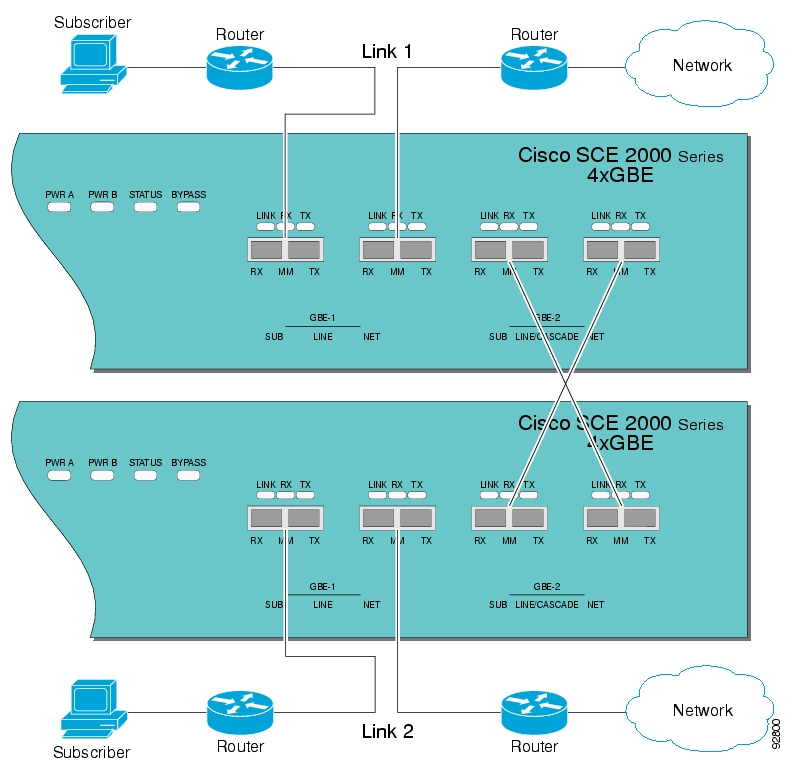
The SCE platform has several types of mechanisms for detecting failures:
Internal failure detection — The SCE platform monitors for hardware and software conditions such as overheating and fatal software errors.
Inter-device failure detection — The SCE platform sends periodic keep-alive messages via the cascade ports
SCE platform-Subscriber Manager (SM) communication failure detection — A failure to communicate with the SM may be regarded as a cause for fail over. However, this communication failure is not necessarily a problem in the SCE platform. If the connection to the SM of the active SCE platform has failed, while the connection to the SM of the standby SCE platform is alive, a fail over process will be initiated to allow the SCE platform proper exchange of information between the SCE platforms and the SM.
Link failure — The system monitors all three types of links for failures:
Traffic port link failure — Traffic cannot flow through the SCE platform.
Cascade port link failure — Traffic cannot flow between the SCE platforms through the cascade ports.
Management port link failure — This is not a failure that interrupts traffic on the link in and of itself. However, when SM is used, management port link failure will cause an SM connection failure and this, in turn, will be declared as a failure of the SCE platform.
This type of failure, in most cases, does not require reboot of the SCE platform. When the connection with the SM is re-established the SCE platform is again ready for hot standby. If both SCE platforms lose their connections with the SM, it is assumed that it is the SM which has failed, thus, no action will be taken in the SCE platform.
The SCE platforms are transparent at Layers 2 and 3. The SCE platform operates in promiscuous mode, and the network elements on both sides of the SCE platform, are using the MAC address of the other network element when forwarding traffic.
In order to assist the network elements on both sides of the SCE platform to identify the link failures as quickly as possible, the SCE platform supports a functionality of reflecting to the other side of the SCE platforms events of link failure. When the link on one side of the SCE platform fails, the corresponding link on the other side is forced down, to reflect the failure.
Link failure reflection is done on the traffic ports. When operating in deployments of single SCE platform with two data links, link failure is reflected between the two ports of each link.
When working with two cascaded SCE platforms, link failure is reflected in two cases:
Reflection between the traffic ports of each SCE platform.
If there is a failure in the cascade port link, the two SCE platforms can no longer support proper processing of the two links, since the traffic flowing on the standby SCE platform’s link must be forwarded to the active SCE platform for processing. In this case the link failure is reflected from the cascade ports to the traffic ports of the standby SCE platform, in order to force the network to switch all the traffic only through the link of the active SCE platform.
Link failure reflection is supported both when the SCE platform is operational and when it is in failure/boot status.
Link reflection, like fail-over, is dependent on the bypass mechanism of the SCE platform.
Use the following commands to force a virtual failure condition, and to exit from the failure condition when performing an application upgrade. (See Application Upgrade.)
The fail over solution requires two SCE platforms connected in a cascade manner.
In fail over solution, one of the SCE platforms is used as the active SCE platform and the other is used as the standby. Although traffic enters both the active and the standby SCE platforms, all traffic processing takes place in the SCE platform which is currently the active one. The active SCE platform processes the traffic coming on both links, its own link and the link connected to the standby SCE platform, as follows
All traffic entering the active SCE platform through its traffic ports is processed in that SCE platform and then forwarded to the line.
All traffic entering the standby SCE platform through its traffic ports is forwarded through the cascade ports to the active SCE platform where it is processed, and then returned to the standby SCE platform through the cascade ports to be forwarded to the original line from which it came.
Since only one SCE platform processes all traffic at any given time, split flows, which are caused by asymmetrical routing, that exist in the two data links are handled correctly.
In order to support subscriber-state fail-over, both SCE platforms hold subscriber states for all parties, and subscriber state updates are exchanged between the active SCE platform and the standby. This way, if the active SCE platform fails, the standby SCE platform is able to start serving the line immediately with a minimum loss of subscriber-state.
The two SCE platforms also use the cascade channel for exchanging periodic keep-alive messages.
In fail over solution, the two SCE platforms exchange keep alive messages via the cascade ports. This keep alive mechanism enables fast detection of failures between the SCE platforms and fast fail over to the standby SCE platform when required.
If the active SCE platform fails, the standby SCE platform then assumes the role of the active SCE platform.
The failed SCE platform uses its electrical bypass mechanism, which is a hardware entity that is separate from the main board and processors, to forward traffic to the other SCE platform, and to forward processed traffic back to the link. The previously standby SCE platform now processes all the traffic of this other link that is forwarded to it by the previously active SCE platform in addition to the traffic of its own link.
When the failed SCE platform recovers, it will remain in standby, while the previously standby SCE platform remains active. Switching the SCE platforms back to their original roles may be performed manually, if required, after the failed SCE platform has either recovered or been replaced.
If the failure is in the standby SCE platform, it will continue to forward traffic to the active SCE platform and back to its link, while the active SCE platform continues to provide its normal processing functionality to the traffic of the two links.
There are two user-configurable options that are relevant in a situation when an SCE platform fails:
Bypass — Maintain the link in bypass mode (continue sending traffic to the other SCE platform, and then continue forwarding the processed traffic back to the link). The incoming traffic in the failed SCE platform is forwarded to the working SCE platform, where it is processed and then sent back to the original SCE platform and back to the link.
Effect on the network link — negligible.
Effect on the SCE platform functionality — The effect on the SCE platform functionality is dependent on the failed SCE platform.
If the failure is in the standby SCE platform — the active SCE platform continues providing its normal functionality, processing the traffic of the two links.
If the failure is in the active SCE platform — the standby SCE platform takes over processing the traffic, and becomes the active SCE platform.
This is the default configuration, and is also the recommended option for most deployments.
Cutoff — Change the link of the failed SCE platform to cutoff (layer 1) forcing the network to switch all traffic through the line of the working SCE platform. This will, of course, decrease the network capacity by 50%, but may be useful in some cases.
Effect on the network — The network looses 50% of its capacity (until the failed SCE platform has recovered).
Effect on the SCE platform functionality — The effect on the SCE platform functionality is dependent on the failed SCE platform:
If the failure is in the standby SCE platform — SCE platform continues providing its normal functionality, processing the traffic of its own link.
If the failure is in the active SCE platform — the standby SCE platform takes over processing the traffic, and becomes the active SCE platform. This option is available for use in special cases, and requires specific configuration.
The effect of a failure in the cascade connection between the two SCE platforms depends on whether one or both connections fail:
Only one cascade connection is down — In this case, both SCE platforms can still communicate, so each still knows the status of the peer.
As long as one cascade connection remains up, the standby will cut off its traffic links so that all traffic is routed via the active SCE platform. Therefore, split flow is avoided, but at the expense of half line capacity.
Both cascade links are down — In this case, neither SCE platform knows anything about the status of the peer. Each platform then works in standalone mode, which means that each SCE platform processes on its own traffic, only. This results in split flows.
This section outlines the installation procedures for a redundant solution with two cascaded SCE platforms.
Refer to the Cisco SCE 2000- Installation and Configuration Guide for information on topologies and connections.
Refer to the Cisco Service Control Engine (SCE) CLI Command Reference for details of the CLI commands.
Warning
When working with two SCE platforms with split-flow and redundancy, it is extremely important to follow this installation procedure.
To install a cascaded system, complete the following steps:
Install both SCE platforms, power them up, and perform the initial system configuration.
Connect both SCE platforms to the management station.
Connect the cascade ports. The cascade ports must be connected directly in Layer 1 (dark fibers), not through a switch.
Set topology configurations for each SCE platform via the connection-mode options. (See Topology-Related Parameters for Redundant Topologies.)
Make sure that the SCE platforms have synchronized and active SCE platform was selected.
Use the
show interface linecard 0 connection-modecommand.If you want to start with bypass/sniffing, change the link mode to your required mode in both SCE platforms on both links. The bypass mode will be applied only to the active SCE platform. (See Link Mode.)
Make sure that the link mode is as you required. (See Monitoring the System.)
Use the
show interface linecard 0 link modecommand.Connect the traffic port of SCE platform #1. This will cause a momentary down time until the network elements from both sides of the SCE platform auto-negotiate with it and start working (when working inline).
Connect the traffic port of SCE platform #2, this will cause a momentary down time until the network elements from both sides of the SCE platform auto-negotiate with it and start working (when working inline).
When full control is needed, change the link mode on both SCE platforms on both links to ‘forwarding’. It is recommended to first configure the active SCE platform and then the standby. (See Link Mode.)
You can now start working with the Subscriber Manager.
This section specifies the procedure for recovery after a failure. The purpose of the recovery procedure is to restore the system to fully functional status. After the recovery procedure, the behavior of the system is the same as after installation.
A failed SCE platform may either recover automatically or be replaced (manual recovery). Whether recovery is automatic or manual depends on the original cause of the failure:
Power failure — manual or automatic recovery can be implemented.
Any failure resulting in a reboot — manual or automatic recovery can be implemented (this is configurable).
3-consecutive reboots within half an hour — manual recovery only
Cascade ports link-failure — automatic recovery when link revives.
Traffic link failure — automatic recovery when link revives.
Failure in the communications with the SM — automatic by SM decisions after connection is re-established.
Hardware malfunction — manual recovery, after replacing the malfunctioning SCE platform.
This is done in two stages, first manual installation steps performed by the technician, and then automatic configuration steps performed by the system.
Manual steps:
Disconnect the failed SCE platform from the network.
Connect a new SCE platform to the management link and the cascade links (leave network ports disconnected.)
Configure the SCE platform.
Basic network configurations done manually (first time).
Load application software (Service Control Application Suite for Broadband) to the SCE platform. Provide application configuration.
Connect the traffic ports to the network links.
Reboot of the SCE platform.
Basic network configurations.
Establishment of inter-SCE platform communication.
Selection of the active SCE platform.
Synchronization of the recovered SCE platform with the SM.
Copying updated subscriber states from the active SCE platform to the standby.
This section presents CLI commands relevant to the configuration and monitoring of a redundant system.
Use the following commands to configure and monitor a redundant system:
connection-mode
[no] force failure-condition
Show interface linecard 'number' connection-mode
Show interface linecard 'number' physically-connected linksAll four of the topology-related parameters are required when configuring a redundant topology.
Connection mode — Redundancy is achieved by cascading two SCE platforms. Therefore the connection mode for both SCE platforms may be either:
Inline-cascade
Receive-only-cascade
Physically-connected-links — For each of the cascaded SCE platforms, this parameter defines the number of the link (Link 0 or Link 1) connected to this SCE platform.
Priority — For each of the cascaded SCE platforms, this parameter defines whether it is the primary or secondary device.
On-failure — For each of the cascaded SCE platforms, this parameter determines whether the system cuts the traffic or bypasses it when the SCE platform either has failed or is booting.
Use the following command to configure the connection mode, including the following parameters:
inline/receive only
physically connected links
behavior upon failure of the SCE platform
primary/secondary
To configure the connection mode, use the following command:
From the SCE(config if)# prompt, type
connection-modeinline-cascade/receive-only-cascade[physically-connected-links{link-0/link-1}][priority{primary/secondary}][on-failure{bypass/cutoff}]and press Enter.
Example 1
Use the following command to configure the primary SCE platform in a two-SCE platform inline topology. Link 1 is connected to this SCE platform and the behavior of the SCE platform if a failure occurs is bypass.
SCE(config if)# connection-mode inline-cascade physically-connected-links link-1 priority primary on-failure bypassExample 2
Use the following command to configure the SCE platform that might be cascaded with the SCE platform in Example 1. This SCE platform would have to be the secondary SCE platform, and Link 0 would be connected to this SCE platform, since Link 1 was connected to the primary. The connection mode would be the same as the first, and the behavior of the SCE platform if a failure occurs is also bypass.
SCE(config if)# connection-mode inline-cascade physically-connected-links link-0 priority secondary on-failure bypass
Use the following commands to view the current connection mode and link mode parameters.
To view the current connection mode, use the following command:
From the SCE# prompt, type
show interface linecard 0 connection-modeand press Enter.
In a redundant solution, it is important that firmware and/or application upgrades be performed in such a way that line and service are preserved.
Refer to the following sections for instructions on how to perform these procedures on two cascaded SCE platforms:
Upgrade the firmware only
Upgrade the application only
Upgrade both the firmware and the application at the same time
Note
When upgrading only one component (either firmware only or application only), always verify that the upgraded component is compatible with the component that was not upgraded.
Install package on both SCE platforms (open the package and copy configuration).
Reload the standby SCE platform.
Wait until the standby finishes synchronizing and is ready to work.
Make sure that the connection mode configurations are correct.
Reload the active SCE platform.
After the former active SCE platform reboots and is ready to work manually, it may be left as standby or we can manually switch the SCE platforms to their original state.
Unload the application in the standby SCE platform.
Load new application to the standby SCE platform.
Make sure that the connection mode configurations are correct.
Wait until the standby SCE platform finishes synchronizing and is ready to work.
Force failure condition in the active SCE platform.
Upgrade the application in the former active SCE platform.
Remove the force failure condition in that platform.
After the former active SCE platform recovers and is ready to work, it may remain the standby or can be manually switched back to active.
In the standby SCE platform:
Uninstall the application.
Upgrade the firmware (this includes a reboot).
Install the new application.
Force-failure in the active SCE platform.
This makes the updated SCE platform the active one, and it begins to give the NEW service.
Repeat step 1 for the (now) standby SCE platform.
(Since this includes a reboot, it is not necessary to undo the force failure command.)
This chapter describes the ability of the SCE platform to identify and prevent DDoS attacks, and the various procedures for configuring and monitoring the Attack Filter Module.
The SCE platform includes extensive capabilities for identifying DDoS attacks, and protecting against them.
Attack filtering is performed using specific-IP attack detectors. A specific-IP attack detector tracks the rate of flows (total open and total suspected) in the SCE platform for each combination of IP address (or pair of IP addresses), protocol (TCP/UDP/ICMP/Other), destination port (for TCP/UDP), interface and direction. When the rates satisfy user-configured criteria, it is considered an attack, and a configured action can take place (report/block, notify subscriber, send SNMP trap).
This mechanism is enabled by default, and can be disabled and enabled for each attack type independently.
There are 32 different attack types:
1 — TCP flows from a specific IP address on the subscriber side, regardless of destination port
2 — TCP flows to a specific IP address on the subscriber side, regardless of destination port
3-4 — Same as 1 and 2, but for the opposite direction (subscriber <-> network)
5 — TCP flows from a specific IP address on the subscriber side to a specific IP address on the network side
6 — Same as 5, but for the opposite direction (from the network side to the subscriber side)
7-12 — Same as 1-6 but with a specific destination port common to all flows of the attack (1-6 are port-less attack types, 7-12 are port-based attack types)
13-24 — Same as 1-12 but for UDP instead of TCP
25-28 — Same as 1-4 but for ICMP instead of TCP
29-32 — Same as 1-4 but for Other protocols instead of TCP
When the specific IP attack filter is enabled for a certain attack type, two rates are measured per defined entity:
Rate of new flows
Rate of suspected flows (In general, suspected flows are flows for which the SCOS did not see proper establishment (TCP) or saw only a single packet (all other protocols)).
Separate rate meters are maintained both for each IP address separately (single side) and for IP address pairs (the source and destination of a given flow), so when a specific IP is attacking a specific IP, this pair of IP addresses defines a single incident (dual-sided).
Based on these two metrics, a specific-IP attack is declared if either of the following conditions is present:
The new flows rate exceeds a certain threshold
The suspected flows rate exceeds a configured threshold and the ratio of suspected flows rate to total new flow rate exceeds a configured threshold.
When the rates stop satisfying this criterion, the end of that attack is declared.
Note that specific attack filtering is configured in two steps:
Enabling specific IP filtering for the particular attack type.
Configuring an attack detector for the relevant attack type. Each attack detector specifies the thresholds that define an attack and the action to be taken when an attack is detected.
In addition to specific attack detectors, a default detector exists that can be configured with user-defined thresholds and action, or system defaults may be retained.
In addition, the user can manually override the configured attack detectors to either force or prevent attack filtering in a particular situation.
Specific IP filtering for selected attack types is enabled with the following parameters. These parameters control which of the 32 attack types are being filtered for:
Protocol — TCP, UDP, ICMP, or Other
Attack direction — The direction of the attack may be identified by only one IP address or by two IP addresses:
single side — The attack is identified by either the source IP address or the destination address only.
The filter definition may specify the specific side, or may include any single side attack, regardless of side (both).
dual side (TCP and UDP protocols only) — The attack is identified by both the source and destination IP addresses. In other words, when a specific IP attacks a specific IP, this is detected as one incident rather than as two separate incidents.
Destination port (TCP and UDP protocols only) — Defines whether specific IP detection is enabled or disabled for port-based or port-less detections. Enable port-based detection for TCP/UDP attacks that have a fixed destination port or ports.
The list of destination ports for port-based detection is configured separately. (See Specific Attack Detectors.)
Specific IP detections are identified with the following parameters:
Specific IP address (or two IP addresses for dual-sided detections)
Protocol — TCP, UDP, ICMP or Other
Port — For TCP/UDP attacks that have a fixed destination port
Side — Interface (Subscriber/Network) from which attack packets are sent
Attack-direction — If a single IP address is specified, the IP address is an attack-source or an attack-destination address.
The system can identify a maximum of 1000 independent, simultaneous attacks.
Once an attack is identified, the system can be instructed to perform any of the following actions:
Report — By default, the attack beginning and end are always reported.
Block — The system will block all attack traffic for the duration of the attack. (The traffic is from or to the attack IP address, depending on whether the IP address is an attack-source or attack-destination)
Notify — Subscriber notification. When the IP address identified is mapped to a particular subscriber context, the system can be configured to notify the subscriber of the fact that he is under an attack (or a machine in his network is generating such an attack), using HTTP Redirect.
Alarm — The system will generate an SNMP trap each time an attack starts and stops.
Attack detection and handling are user-configurable. The remainder of this chapter explains how to configure and monitor attack detection.
There are three thresholds that are used to define an attack. These thresholds are based on meters that are maintained by the SCE platform for each IP address or pair of addresses, protocol, interface and attack-direction.
open flow rate — A flow for which some traffic was seen. Any packet seen for a new flow is enough to declare this flow an open flow.
The rate is measured in new flows per minute.
suspected flow rate — A suspected flow is one that was opened, but did not become an established flow.
The rate is measured in new flows per minute.
suspected flow ratio — The ratio of the suspected flow rate to the open flow rate.
As explained above, a specific-IP attack is declared if either of the following conditions is present:
The open flows rate exceeds the threshold
The suspected flows rate exceeds the threshold and the suspected flows ratio exceeds the threshold.
The values for each attack type will have a separate configured default value.
In general, for a given protocol, the suspected flows rate threshold should be lower for a port-based detection than for a port-less detection. This is because flows with a given IP address and a common destination port are metered twice:
By themselves — to detect a port-based attack
Together with flows with the same IP address and different destination ports — to detect a port-less attack
If a port-based attack occurs, and the rate of flows is above both thresholds (port-based thresholds and the port-less thresholds), it is desirable for the port-based attack to be detected before the port-less attack. Similarly, this threshold should be lower for dual-IP detections then for single-IP detections.
The user may define values for these thresholds that override the preset defaults. It is also possible to configure specific thresholds for certain IP addresses and ports (using access lists and port lists). This enables the user to set different detection criteria for different types of network entities, such as a server farm, DNS server, or large enterprise customer.
Attack handling can be configured as follows:
Configuring the action:
Report — Attack packets are processed as usual, and the occurrence of the attack is reported.
Block — Attack packets are dropped by the SCE platform, and therefore do not reach their destination.
Regardless of which action is configured, two reports are generated for every attack: one when the start of an attack is detected, and one when the end of an attack is detected.
Configuring subscriber-notification (notify):
Enabled — If the subscriber IP address is detected to be attacked or attacking, the subscriber is notified about the attack.
Disabled — The subscriber is not notified about the attack.
Configuring sending an SNMP trap (alarm):
Enabled — An SNMP trap is sent when attack begins and ends.
The SNMP trap contains the following information fields:
A specific IP address or
Protocol (TCP, UDP, ICMP or Other)
Interface (User/Network) behind which the detected IP address is found. This is referred to below as the attack ‘side’
Attack direction (whether the IP address is the attack source or the attack destination).
Type of threshold breached (open- flows / ddos- suspected- flows) [‘ attack- start’ traps only]
Threshold value breached [‘ attack- start’ traps only]
Action taken (report, block) indicating what was the action taken by the SCE platform in response to the detection
Amount of attack flows blocked/ reported providing the total number of flows detected during the attack [‘ attack- stop’ traps only]
Disabled — No SNMP trap is sent.
When an attack is identified, if the IP address is detected on the subscriber side and is mapped to a subscriber, the system notifies the application about the attack. This enables the application to notify the subscriber about the attack on-line by redirecting HTTP requests of this subscriber to a server that will notify it of the attack.
In addition, when blocking TCP traffic, the system can be configured not to block a specified port in order to make this redirection possible. This port is then considered to be un-blockable.
Note that subscriber-notification can only function if supported by the Service Control Application currently loaded to the SCE platform, and the application is configured to activate this capability. To verify whether the application you are using supports attack subscriber notification, and for details about enabling attack subscriber notification in the application, please refer to the documentation of the relevant Service Control Application.
The SCE platform has two ways of handling an attack: by software or by hardware. Normally, attacks are handled by software. This enables the SCE platform to accurately measure the attack flows and to instantly detect that an attack has ended.
However, very strong attacks cannot be handled successfully by the software. If the software cannot adequately handle an attack, the resulting high CPU load will harm the service provided by the SCE platform (normal traffic classification and control). An attack that threatens to overwhelm the software will, therefore, be automatically filtered by the hardware.
When the hardware is used to filter the attack, the software has no knowledge of the attack packets, and therefore the following side effects occur:
The number of attack flows is greatly under-estimated by the software. This means that the total amount of flows in the attack reported by the CLI (
show interface linecard attack-filter current-attacks) is considerably lower than the actual amount.Similarly, the reported attack flow rate (also reported by the CLI) is also considerably lower than the actual rate. Usually a rate of 0 is measured by the software.
There is considerable delay in detecting the end of the attack. The delay in detecting the end of attack is limited by two upper bounds.
The first upper bound depends on the configured action, as follows:
Report — a delay of no more than 8 minutes
Block — a delay of no more than 64 minutes
A second upper bound for the delay is one minute more than actual duration of the attack (for example, maximum delay for detecting the end of an attack lasting three minutes is four minutes).
The following examples illustrate the interaction of these two upper bounds:
For an attack lasting two minutes, the maximum delay in detecting the end will be three minutes, regardless of configured action
For an attack lasting two hours whose configured action is 'report', the maximum delay in detecting the end will be eight minutes
For an attack lasting two hours whose configured action is 'block', the maximum delay in detecting the end will be 64 minutes
Hardware attack filtering is an automatic process and is not user-configurable. However, due to the effects of hardware attack filtering on attack reporting, it is important to be aware of when hardware processing has been activated, and so monitoring of hardware filtering is essential. There are two ways to do this (see Monitoring Attack Filtering):
Check the "HW-filter" field in the
show interface linecard attack-filter current-attackscommand.Check the "HW-filter" field in the attack log file.
The Cisco attack detection mechanism is controlled by defining and configuring special entities called Attack Detectors.
There is one attack detector called ‘default’, which is always enabled, and 99 attack detectors (numbered 1-99), which are disabled by default. Each detector (both the default and detectors 1-99) can be configured with a separate action and threshold values for all 32 possible attack types.
When detectors 1-99 are disabled, the default attack detector configuration determines the thresholds used for detecting an attack, and the action taken by the SCE platform when an attack is detected. For each attack type, a different set of thresholds and action can be set. In addition, subscriber-notification and SNMP traps (alarm) can be enabled or disabled in the same granularity.
The default attack detector should be configured with values that reflect the desired SCE platform behavior for the majority of the traffic flows flowing through it. However, it is not feasible to use the same set of values for all the traffic that traverses through the SCE platform, since there might be some network entities for which the characteristics of their normal traffic should be considered as an attack when coming from most other network elements. Here are two common examples:
A DNS server is expected to be the target of many short DNS queries. These queries are typically UDP flows, each flow consisting of two packets: The request and the response. Normally, the SCE platform considers all UDP flows that are opened to the DNS server as DDoS-suspected flows, since these flows include less than 3 packets. A DNS server might serve hundreds of DNS requests per second at peak times, and so the system should be configured with a suitable threshold for DDoS-suspected flows for protocol = UDP and direction = attack-destination. A threshold value of 1000 flows/second would probably be suitable for the DNS server. However, this threshold would be unsuitable for almost all other network elements, since, for them, being the destination of such large rate of UDP flows would be considered an attack. Therefore setting a threshold of 1000 for all traffic is not a good solution.
The subscriber side of the SCE platform might contain many residential subscribers, each having several computers connected through an Internet connection, and each computer having a different IP address. In addition, there might be a few business subscribers, each using a NAT that hides hundreds of computers behind a single IP address. Clearly, the traffic seen for an IP address of a business subscriber contains significantly more flows than the traffic of an IP address belonging to a residential subscriber. The same threshold cannot be adequate in both cases.
To let the SCE platform treat such special cases differently, the user can configure non-default attack detectors in the range of 1-99. Like the default attack detector, non-default attack detectors can be configured with different sets of values of action and thresholds for every attack type. However, in order to be effective, a non-default attack detector must be enabled and must be assigned an ACL (access control list). The action and thresholds configured for such attack detector are effective only for IP addresses permitted by the ACL. Non-default attack-detectors can be assigned a label for describing their purpose, such as ‘DNS servers’ or ‘Server farm’.
Non-default attack detectors are effective only for attack types that have been specifically configured. This eliminates the need to duplicate the default attack detector configuration into the configuration non-default attack detectors, and is best illustrated with an example: Suppose an HTTP server on the subscriber side of the SCE platform is getting many requests, which requires the use of a non-default attack detector for configuring high threshold values for incoming TCP flow rates. Assume attack detector number 4 is used for this purpose; hence it is enabled, and assigned an ACL which permits the IP address of the HTTP server. Also suppose that it is desirable to protect subscribers from UDP attacks, hence the default attack detector is configured to block UDP attacks coming from the network (The default configuration is only to report attacks, not block them). If the HTTP server is attacked by a UDP attack from the network , the configuration of the default attack detector will hold for this HTTP server as well, since attack detector number 4 was not configured for UDP attacks.
For each of the non-default attack detectors, for each of the 32 attack types, there are four configurable settings:
Threshold
Action
Subscriber-notification
Alarm
Each of these four settings can be either configured (with a value or set of values) or not configured. The default state is for all of them is not configured.
For each attack type, the set of enabled attack detectors, together with the default attack detector, forms a database used to determine the threshold and action to take when an attack is detected. When the platform detects a possible attack, it uses the following algorithm to determine the thresholds for attack detection.
Enabled attack detectors are scanned from low to high numbers.
If the IP address is permitted by the ACL specified by the attack detector, and a threshold is configured for this attack type, then the threshold values specified by this attack detector are used. If not, the scan continues to the next attack detector.
If no attack detector matches the IP address/protocol combination, then the values of the default attack detector are used.
The same logic is applied when determining the values to use for the remaining settings: action, subscriber-notification and alarm. The value that is used is the one specified by the lowest-numbered enabled attack detector that has a configured value for the attack type. If none exists, the configuration of the default attack detector is used.
Use the following commands to configure and enable attack detection:
[no] attack-filter protocol <protocol> attack-direction <direction> attack-detector (default|<number>) protocol <protocol> attack-direction <direction> side <side> action <action> [open-flows <number> suspected-flows-rate <number> suspected-flows-ratio <number>] attack-detector (default|<number>) protocol <protocol> attack-direction <direction> side <side> (notify-subscriber|dont-notify-subscriber) attack-detector (default|<number>) protocol <protocol> attack-direction <direction> side <side> (alarm|no-alarm) default attack-detector (default|<number>) protocol <protocol> attack-direction <direction> side <side> default attack-detector default default attack-detector <number> default attack-detector (all-numbered|all) attack-detector <number> access-list comment attack-detector <number> (TCP-dest-ports|UDP-dest-ports) (all|(<port1> [<port2 …])) [no] attack-filter subscriber-notification ports <port1>Note
All the above CLI commands are line interface configuration commands. You must enter line interface configuration mode and see the
SCE(config if)#prompt displayed.By default, specific-IP detection is enabled for all attack types. You can configure specific IP detection to be enabled or disabled for a specific, defined situation only, depending on the following options:
For a selected protocol only.
For TCP and UDP protocols, for only port-based or only port-less detections.
For a selected attack direction, either for all protocols or for a selected protocol.
The following options are available:
protocol — The specific protocol for which specific IP detection is to be enabled or disabled.
Default — all protocols (no protocol specified)
attack direction — Defines whether specific IP detection is enabled or disabled for single sided or dual sided attacks.
Default — all directions
destination port (TCP and UDP protocols only) — Defines whether specific IP detection is enabled or disabled for port-based or port-less detections.
Default — both port-based or port-less
Use the "no" form of the command to disable the configured specific-IP detection.
To enable specific-IP detection, use the following command:
From the
SCE(config if)#prompt, typeattack-filter [protocol (((TCP|UDP) [dest-port(specific|not-specific|both)])|ICMP|other)] [attack-direction(single-side-source|single-side-destination|single-side-both|dual-sided|all)] and press Enter.To enable specific-IP detection for the TCP protocol only for all attack directions, use the following command:
From the
SCE(config if)#prompt, typeattack-filter protocol TCPand press Enter.To enable specific-IP detection for the TCP protocol for port-based detections only for all attack directions, use the following command:
From the
SCE(config if)#prompt, typeattack-filter protocol TCP dest-port specificand press Enter.To enable specific-IP detection for the TCP protocol for port-based detections only for dual-sided attacks, use the following command:
From the
SCE(config if)#prompt, typeattack-filter protocol TCP dest-port specific attack-direction dual-sidedand press Enter.Use these commands to configure the values for the default attack detector for the following parameters:
Attack handling action
Thresholds
Subscriber notification
Sending an SNMP trap
If a specific attack detector is defined for a particular attack type, it will override the configured default attack detector.
The default values for the default attack detector are:
Action — Report
Thresholds — Varies according to the attack type
Subscriber notification — Disabled
Sending an SNMP trap — Disabled
The following options are available:
attack-detector — The attack detector being configured; in this case, the default attack detector.
protocol — Defines the protocol to which the default attack detector applies.
attack direction — Defines whether the default attack detector applies to single sided or dual sided attacks.
destination port {TCP and UDP protocols only) — Defines whether the default attack detector applies to port-based or port-less detections.
side — Defines whether the default attack detector applies to attacks originating at the subscriber or network side.
action — Default action:
report (default) — Report beginning and end of the attack by writing to the attack-log.
block — Block all further flows that are part of this attack, the SCE platform drops the packets.
Thresholds:
open-flows-rate — Default threshold for rate of open flows.
suspected-flows-rate — Default threshold for rate of suspected DDoS flows.
suspected-flows-ratio — Default threshold for ratio of suspected flow rate to open flow rate.
Use the appropriate keyword to enable or disable subscriber notification by default:
notify-subscriber — Enable subscriber notification.
dont-notify-subscriber — Disable subscriber notification.
Use the appropriate keyword to enable or disable sending an SNMP trap by default:
alarm — Enable sending an SNMP trap.
no-alarm — Disable sending an SNMP trap.
To define the default action and optionally the default thresholds, complete the following steps:
From the
SCE(config if)#prompt, typeattack-detector default protocol (((TCP|UDP) [dest-port (specific|not- specific|both)])|ICMP|other|all) attack-direction(single-side-source|single-side-destination|single-side-both|dual-sided|all)side (subscriber|network|both) [action (report|block)] [open-flows-rate<number> suspected-flows-rate <number> suspected-flows-ratio <number>]and press Enter.Use the following command to enable or disable subscriber notification by default.
From the
SCE(config if)# prompt, typeattack-detector default protocol(((TCP|UDP) [dest-port (specific|not- specific|both)])|ICMP|other|all) attack-direction(single-side-source|single-side-destination|single-side-both|dual-sided|all)side (subscriber|network|both)(notify-subscriber|dont-notify-subscriber)and press Enter.Use the following command to enable or disable sending an SNMP trap by default.
From the
SCE(config if)# prompt, typeattack-detector default protocol(single-side-source|single-side-destination|single-side-both|dual-sided|all)side (subscriber|network|both)(alarm|no-alarm)and press Enter.Use the following command to delete user-defined default values for action, thresholds, subscriber notification, and sending an SNMP trap for a selected set of attack types, and reinstate the system defaults.
To reinstate the system defaults for a selected set of attack types, use the following command:
From the
SCE(config if)#prompt, typedefault attack-detector default protocol (((TCP-port-list|UDP-port-list) [port (specific|not-specific|both)])|ICMP|other|all) attack-direction(single-side-source|single-side-destination|single-side-both|dual-sided|all)side (subscriber|network|both)and press Enter.A specific attack detector may be configured for each possible combination of protocol, attack direction, and side. The SCE platform supports a maximum of 100 attack detectors. Each attack detector is identified by a number (1-100). Each detector can be either disabled (default) or enabled. An enabled attack detector must be configured with the following parameters:
access-list — The number of the Access-Control List (ACL) associated with the specified attack detector. The ACL identifies the IP addresses selected by this detector. (See Access Control Lists.)
For dual-ip detections, the destination IP address is used for matching with the ACL.
Use the "none" keyword to indicate that all IP addresses are permitted by this attack-detector.
This option is useful when using the command to define a port list, and the desired configuration should be set for all IP addresses.
comment — For documentation purposes.
In addition, an enabled attack detector may contain the following settings:
TCP-port-list/UDP-port-list — Destination port list for the specified protocol. TCP and UDP protocols may be configured for specified ports only. This is the list of specified destination ports per protocol.
Up to 15 different TCP port numbers and 15 different UDP port numbers can be specified.
Configuring a TCP/UDP port list for a given attack detector affects only attack types that have the same protocol (TCP/UDP) and are port-based (i.e. detect a specific destination port). Settings for other attack types are not affected by the configured port list(s).
The following settings are configurable for each attack type in each attack detector. Each setting can either be in a 'not configured' state (which is the default), or be configured with a specific value.
action — Action:
report (default) — Report beginning and end of the attack by writing to the attack-log.
block — Block all further flows that are part of this attack, the SCE platform drops the packets.
Thresholds:
open-flows-rate — Threshold for rate of open flows.
suspected-flows-rate — Threshold for rate of suspected DDoS flows.
suspected-flows-ratio — Threshold for ratio of suspected flow rate to open flow rate.
Use the appropriate keyword to enable or disable subscriber notification:
notify-subscriber — Enable subscriber notification.
dont-notify-subscriber — Disable subscriber notification.
Use the appropriate keyword to enable or disable sending an SNMP trap:
alarm — Enable sending an SNMP trap.
no-alarm — Disable sending an SNMP trap.
Use these commands to define thresholds, actions, subscriber notification setting, and sending an SNMP trap for a specific attack detector for selected set of attack types.
To enable a specific attack detector and assign and it an ACL, use the following command:
From the SCE(config if)# prompt, type
attack-detector<number>access-list (<number>|none)comment<comment>and press Enter.To define action and optionally thresholds for a specific attack detector, use the following command:
From the
SCE(config if)#prompt, typeattack-detector<number>protocol (((TCP|UDP) [dest-port (specific|not- specific|both)])|ICMP|other|all) attack-direction(single-side-source|single-side-destination|single-side-both|dual-sided|all)side (subscriber|network|both) [action (report|block)] [open-flows-rate<number> suspected-flows-rate <number> suspected-flows-ratio <number>]and press Enter.Use the following command to set the subscriber notification setting for a given attack detector and selected set of attack types.
To define the subscriber notification setting for a specific attack detector and a selected set of attack types, use the following command:
From the
SCE(config if)#prompt, typeattack-detector<number>protocol ((((TCP|UDP) [dest-port (specific|not-specific|both)])|ICMP|other|all) attack-direction(single-side-source|single-side-destination|single-side-both|dual-sided|all)side (subscriber|network|both) (notify-subscriber|dont-notify-subscriber)and press Enter.Use the following command to enable or disable sending an SNMP trap for a given attack detector and selected set of attack types.
To define the SNMP trap setting for a specific attack detector and selected set of attack types, use the following command:
From the
SCE(config if)# prompt, typeattack-detector<number>protocol(((TCP|UDP) [dest-port (specific|not-specific|both)])|ICMP|other|all) attack-direction(single-side-source|single-side-destination|single-side-both|dual-sided|all)side (subscriber|network|both)(alarm|no-alarm)and press Enter.Use the following command to define the list of destination ports for specific port detections for TCP or UDP protocols.
To define the list of destination ports for TCP or UDP protocols for a specific attack detector, use the following command:
From the
SCE(config if)# prompt, typeattack-detector<number>(TCP-port-list/UDP-port-list)(all|(<port1> [<port2> …]))and press Enter.Use the following command to remove settings of action, thresholds, subscriber notification, and sending an SNMP trap for a specific attack detector and selected set of attack types.
Removing these settings for a given attack type restores them to the default 'not configured' state, which means that the attack detector does not take part in determining the response for attacks of this attack type.
To delete user-defined values for a selected set of attack types, use the following command:
From the
SCE(config if)#prompt, typedefault attack-detector<number>protocol (((TCP|UDP) [dest-port (specific|non-specific|both)])|ICMP|other|all) attack-direction(single-side-source|single-side-destination|single-side-both|dual-sided|all)side (subscriber|network|both)and press Enter.To disable a specific attack detector, configuring it to use the default action, threshold values and subscriber notification for all protocols, attack directions and sides, use the following command:
From the SCE(config if)# prompt, type
default attack-detector<number>and press Enter.The following configuration changes the default user threshold values used for detecting ICMP attacks, and configures an attack-detector with high thresholds for UDP attacks, preventing false detections of two DNS servers (10.1.1.10 and 10.1.1.13) as being attacked.
(First enter the linecard interface configuration mode)
SCE(config)#interface linecard 0(Configure the default ICMP threshold and action.)
SCE(config if)#attack-detector default protocol ICMP attack-directionsingle-side-source action reportopen-flow-rate 1000 suspected-flows-rate 100 suspected-flows-ratio 10(Enable attack detector #1, assign ACL #3 to it, and define the list of UDP destination ports with one port, port 53.)
SCE(config if)#attack-detector 1 access-list 3UDP-ports-list 53 comment "DNS servers"(Define the thresholds and action for attack detector #1)
SCE(config if)# attack-detector 1protocol UDP dest-port specific attack-direction single-side-destination action report open-flow-rate 1000000 suspected-flows-rate 1000000(Enable subscriber notification for attack detector #1)
SCE(config if)#attack-detector 1 protocol UDPdest-port specific attack-direction single-side-destinationside subscriber notify-subscriber(Exit the linecard interface configuration mode)
SCE(config if)#exit(Define the ACL)
SCE(config)#access-list 3 permit 10.1.1.10SCE(config)#access-list 3 permit 10.1.1.13
Subscriber notification is a capability used- for notifying a subscriber in real-time about current attacks involving IP addresses mapped to that subscriber. Subscriber notification is configured on a per-attack-detector level, as explained above, and must also be enabled and configured by the application loaded to the SCE platform, as explained in the appropriate Service Control Application user guide.
In the current solutions, the SCE Platform notifies the subscriber about the attack by redirecting HTTP flows originating from the subscriber to the service provider’s server, that should notify the subscriber that he is under attack. This raises a question regarding TCP attacks originating from the subscriber that are configured with block action. Such attacks cannot normally be notified to the subscriber using HTTP redirection, since all HTTP flows originating from the subscriber are TCP flows, and they are therefore blocked along with all other attack flows. In order to enable effective use of HTTP redirect, there is a CLI command that prevents blocking of TCP flows originating from the subscriber to a specified TCP port, even when the above scenario occurs.
You can define a port to be used as the subscriber notification port. The attack filter will never block TCP traffic from the subscriber side of the SCE platform to this port, leaving it always available for subscriber notification.
After configuring the attack detectors, the SCE platform automatically detects attacks and handles them according to the configuration. However, there are scenarios in which a manual intervention is desired, either for debug purposes, or because it is not trivial to reconfigure the SCE platform attack-detectors properly. For example:
The SCE platform has detected an attack, but the user knows this to be a false alarm. The proper action that should be taken by the user is to configure the system with higher thresholds (for the whole IP range, or maybe for specific IP addresses or ports). However, this might take time, and, if attack handling is specified as ‘Block’, the user may wish to stop the block action for this specific attack quickly, leaving the configuration changes for a future time when there is time to plan the needed changes properly.
Use the dont-filter command described below for this type of case.
An ISP is informed that one of his subscribers is being attacked by a UDP attack from the network side. The ISP wants to protect the subscriber from this attack by blocking all UDP traffic to the subscriber, but unfortunately the SCE platform did not recognize the attack. (Alternatively, it could be that the attack was recognized, but the configured action was ‘report’ and not ‘block’).
Use the force-filter command described below for this type of case.
The user can use the CLI attack filtering commands to do the following:
Configure a dont-filter command to prevent or stop filtering of an attack related to a specified IP address
Configure a force-filter command to force filtering (with a specific action) of an attack related to a specified IP address
Use the following commands to either force or prevent attack filtering:
[no] attack-filter dont-filter
[no] attack-filter force-filter Attack filtering can be prevented for a specified IP address and attack type by executing a dont-filter CLI command. If filtering is already in process, it will be stopped. When attack filtering has been stopped, it remains stopped until explicitly restored by another CLI command (either force-filter or no dont-filter).
To configure a dont-filter setting for a specified situation, use the following command:
From the
SCE(config if)#prompt, typeattack-filter dont-filter protocol (((TCP|UDP) [dest-port (<port-number>|not-specific))|ICMP|other) attack-direction(((single-side-source|single-side-destination|single-side-both)ip<IP-address>)|(dual-sidedsource-ip<IP-address>destination-ip<IP-address>))side (subscriber|network|both)and press Enter.
To remove a dont-filter configuration for a specified situation, use the following command:
From the
SCE(config if)#prompt, typeno attack-filter dont-filter protocol (((TCP|UDP) [dest-port (<port-number>|not-specific))|ICMP|other) attack-direction(((single-side-source|single-side-destination|single-side-both)ip<IP-address>)|(dual-sidedsource-ip<IP-address>destination-ip<IP-address>))side (subscriber|network|both)and press Enter.
To remove all dont-filter configurations, use the following command:
From the
SCE(config if)#prompt, typeno attack-filter dont-filter alland press Enter.
Attack filtering can be forced for a specified IP address/protocol. If filtering is already in process, it will be stopped. Forced attack filtering will continue until undone by an explicit CLI command (either no force-filter or dont-filter).
To configure a force-filter setting for a specified situation, use the following command:
From the
SCE(config if)#prompt, typeattack-filter force-filter action (report|block)protocol (((TCP|UDP) [dest-port (<port-number>|not-specific))|ICMP|other) attack-direction(((single-side-source|single-side-destination|single-side-both)ip<IP-address>)|(dual-sidedsource-ip<IP-address>destination-ip<IP-address>))side (subscriber|network|both)[notify-subscriber]and press Enter.
To remove a force-filter configuration for a specified situation, use the following command:
From the
SCE(config if)#prompt, typeno attack-filter force-filter protocol (((TCP|UDP) [dest-port (<port-number>|not-specific))|ICMP|other) attack-direction(((single-side-source|single-side-destination|single-side-both)ip<IP-address>)|(dual-sidedsource-ip<IP-address>destination-ip<IP-address>))side (subscriber|network|both)and press Enter.
To remove all force-filter configurations, use the following command:
From the
SCE(config if)#prompt, typeno attack-filter force-filter alland press Enter.
Use these commands to monitor attack detection and filtering:
show interface linecard 0 attack-detector
show interface linecard 0 attack-filter
show interface linecard 0 attack-filter query
show interface linecard 0 attack-filter current-attacks
show interface linecard 0 attack-filter dont-filter
show interface linecard 0 attack-filter force-filter
show interface linecard 0 attack-filter subscriber-notification ports
Note
All the above CLI commands are viewer commands. You must see the SCE> prompt displayed.
To display a specified attack detector configuration, use the following command:
From the
SCE#prompt, typeshow interface linecard 0 attack-detector<number>and press Enter.The following information is displayed:
Protocol
Side — Whether the attack detector applies to attacks originating at the subscriber or network side.
Direction — Whether the attack detector applies to single sided or dual sided attacks.
Action to take if an attack is detected.
Thresholds:
open-flows-rate — Default threshold for rate of open flows (new open flows per second).
suspected-flows-rate — Default threshold for rate of suspected DDoS flows (new suspected flows per second).
suspected-flows-ratio — Default threshold for ratio of suspected flow rate to open flow rate.
Subscriber notification — enabled or disabled.
Alarm: sending an SNMP trap enabled or disabled.
Example
SCE#>show interface LineCard 0 attack-detector 1
Detector #1:
Comment: 'Sample'
Access-list: 1
Effective only for TCP port(s) 21,23,80
Effective for all UDP ports

Protocol|Side|Direction  ||Action|     Thresholds                |Sub- |Alarm
        |    |           ||      |Open flows|Ddos-Suspected flows|notif|
        |    |           ||      |rate      |rate        |ratio  |     |
--------|----|-----------||------|----------|------------|-------|-----|-----
TCP     |net.|source-only||      |          |            |       |     |
TCP     |net.|dest-only  ||      |          |            |       |     |
TCP     |sub.|source-only||      |          |            |       |     |
TCP     |sub.|dest-only  ||      |          |            |       |     |
TCP     |net.|source+dest||      |          |            |       |     |
TCP     |sub.|source+dest||      |          |            |       |     |
TCP+port|net.|source-only||Block |          |            |       |     |Yes
TCP+port|net.|dest-only  ||      |          |            |       |     |
TCP+port|sub.|source-only||Block |          |            |       |     |Yes
TCP+port|sub.|dest-only  ||      |          |            |       |     |
TCP+port|net.|source+dest||      |          |            |       |     |
TCP+port|sub.|source+dest||      |          |            |       |     |
UDP     |net.|source-only||      |          |            |       |     |
UDP     |net.|dest-only  ||      |          |            |       |     |
UDP     |sub.|source-only||      |          |            |       |     |
UDP     |sub.|dest-only  ||      |          |            |       |     |
UDP     |net.|source+dest||      |          |            |       |     |
UDP     |sub.|source+dest||      |          |            |       |     |
UDP+port|net.|source-only||      |          |            |       |     |
UDP+port|net.|dest-only  ||      |          |            |       |     |
UDP+port|sub.|source-only||      |          |            |       |     |
UDP+port|sub.|dest-only  ||      |          |            |       |     |
UDP+port|net.|source+dest||      |          |            |       |     |
UDP+port|sub.|source+dest||      |          |            |       |     |
ICMP    |net.|source-only||      |          |            |       |     |
ICMP    |net.|dest-only  ||      |          |            |       |     |
ICMP    |sub.|source-only||      |          |            |       |Yes  |
ICMP    |sub.|dest-only  ||      |          |            |       |     |
other   |net.|source-only||      |          |            |       |     |
other   |net.|dest-only  ||      |          |            |       |     |
other   |sub.|source-only||      |          |            |       |     |
other   |sub.|dest-only  ||      |          |            |       |     |

Empty fields indicate that no value is set and configuration from
the default attack detector is used.
SCE#>
To display the default attack detector configuration, use the following command:
From the
SCE#prompt, typeshow interface linecard 0 attack-detector defaultand press Enter.
Example
SCE#>show interface LineCard 0 attack-detector default
Default detector:

Protocol|Side|Direction  ||Action|     Thresholds                |Sub- |Alarm
        |    |           ||      |Open flows|Ddos-Suspected flows|notif|
        |    |           ||      |rate      |rate        |ratio  |     |
--------|----|-----------||------|----------|------------|-------|-----|-----
TCP     |net.|source-only||Report|      1000|         500|50     |No   |No
TCP     |net.|dest-only  ||Report|      1000|         500|50     |No   |No
TCP     |sub.|source-only||Report|      1000|         500|50     |No   |No
TCP     |sub.|dest-only  ||Report|      1000|         500|50     |No   |No
TCP     |net.|source+dest||Report|       100|          50|50     |No   |No
TCP     |sub.|source+dest||Report|       100|          50|50     |No   |No
TCP+port|net.|source-only||Report|      1000|         500|50     |No   |No
TCP+port|net.|dest-only  ||Report|      1000|         500|50     |No   |No
TCP+port|sub.|source-only||Report|      1000|         500|50     |No   |No
TCP+port|sub.|dest-only  ||Report|      1000|         500|50     |No   |No
TCP+port|net.|source+dest||Report|       100|          50|50     |No   |No
TCP+port|sub.|source+dest||Report|       100|          50|50     |No   |No
UDP     |net.|source-only||Report|      1000|         500|50     |No   |No
UDP     |net.|dest-only  ||Report|      1000|         500|50     |No   |No
UDP     |sub.|source-only||Report|      1000|         500|50     |No   |No
UDP     |sub.|dest-only  ||Report|      1000|         500|50     |No   |No
UDP     |net.|source+dest||Report|       100|          50|50     |No   |No
UDP     |sub.|source+dest||Report|       100|          50|50     |No   |No
UDP+port|net.|source-only||Report|      1000|         500|50     |No   |No
UDP+port|net.|dest-only  ||Report|      1000|         500|50     |No   |No
UDP+port|sub.|source-only||Report|      1000|         500|50     |No   |No
UDP+port|sub.|dest-only  ||Report|      1000|         500|50     |No   |No
UDP+port|net.|source+dest||Report|       100|          50|50     |No   |No
UDP+port|sub.|source+dest||Report|       100|          50|50     |No   |No
ICMP    |net.|source-only||Report|       500|         250|50     |No   |No
ICMP    |net.|dest-only  ||Report|       500|         250|50     |No   |No
ICMP    |sub.|source-only||Report|       500|         250|50     |No   |No
ICMP    |sub.|dest-only  ||Report|       500|         250|50     |No   |No
other   |net.|source-only||Report|       500|         250|50     |No   |No
other   |net.|dest-only  ||Report|       500|         250|50     |No   |No
other   |sub.|source-only||Report|       500|         250|50     |No   |No
other   |sub.|dest-only  ||Report|       500|         250|50     |No   |No

SCE#>
To display all attack detector configurations, use the following command:
From the
SCE#prompt, typeshow interface linecard 0 attack-detector alland press Enter.
To display the attack filter state (enabled or disabled), use the following command:
From the
SCE#prompt, typeshow interface linecard 0 attack-filterand press Enter.
Example
SCE#>show interface LineCard 0 attack-filter
Enabled state :
------------------

Protocol  |Direction   |State
----------|------------|------------
TCP       |source-only |enabled
TCP       |dest-only   |enabled
TCP       |dest+source |enabled
TCP+port  |source-only |enabled
TCP+port  |dest-only   |enabled
TCP+port  |dest+source |enabled
UDP       |source-only |enabled
UDP       |dest-only   |enabled
UDP       |dest+source |enabled
UDP+port  |source-only |enabled
UDP+port  |dest-only   |enabled
UDP+port  |dest+source |enabled
ICMP      |source-only |enabled
ICMP      |dest-only   |enabled
other     |source-only |enabled
other     |dest-only   |enabled
SCE#>
To display the configured threshold values and actions a specified IP address (and port), taking into account the various specific attack detector access list configurations, use the following command:
From the SCE# prompt, type
show interface linecard 0 attack-filter query ((single-sided ip<IP-address>)|(dual-sided source-IP<IP-address>destination-IP<IP-address>)) [dest-port<port-number>] configuredand press Enter.
Example 1
SCE#>show interface linacard 0 attack-filter query single-sided ip 10.1.1.1 configured

Protocol|Side|Dir.|Action|      Thresholds           |dont- |force-|Sub- |Alarm
        |    |    |      |Open flows|Ddos-Susp. flows|filter|filter|notif|
        |    |    |      |rate      |rate      |ratio|      |      |     |
--------|----|----|------|----------|----------|-----|----- |------|-----|-----
TCP     |net.|src.|Report|      1000|       500|   50|No    |No    |   No|   No
TCP     |net.|dst.|Report|      1000|       500|   50|No    |No    |   No|   No
TCP     |sub.|src.|Report|      1000|       500|   50|No    |No    |   No|   No
TCP     |sub.|dst.|Report|      1000|       500|   50|No    |No    |   No|   No
UDP     |net.|src.|Report|      1000|       500|   50|No    |No    |   No|   No
UDP     |net.|dst.|Report|      1000|       500|   50|No    |No    |   No|   No
UDP     |sub.|src.|Report|      1000|       500|   50|No    |No    |   No|   No
UDP     |sub.|dst.|Report|      1000|       500|   50|No    |No    |   No|   No
ICMP    |net.|src.|Report|       500|       250|   50|No    |No    |   No|   No
ICMP    |net.|dst.|Report|       500|       250|   50|No    |No    |   No|   No
ICMP    |sub.|src.|Report|       500|       250|   50|No    |No    |  Yes|   No
        |    |    |      |          |          |     |      |      |  (1)|
ICMP    |sub.|dst.|Report|       500|       250|   50|No    |No    |   No|   No
other   |net.|src.|Report|       500|       250|   50|No    |No    |   No|   No
other   |net.|dst.|Report|       500|       250|   50|No    |No    |   No|   No
other   |sub.|src.|Report|       500|       250|   50|No    |No    |   No|   No
other   |sub.|dst.|Report|       500|       250|   50|No    |No    |   No|   No

(N) below a value means that the value is set through attack-detector #N.
SCE#>
Example 2
SCE#>show interface linacard 0 attack-filter query single-sided ip 10.1.1.1 dest-port 21 configured

Protocol|Side|Dir.|Action|      Thresholds           |dont- |force-|Sub- |Alarm
        |    |    |      |Open flows|Ddos-Susp. flows|filter|filter|notif|
        |    |    |      |rate      |rate      |ratio|      |      |     |
--------|----|----|------|----------|----------|-----|----- |------|-----|-----
TCP+port|net.|src.|Block |      1000|       500|   50|No    |No    |   No|  Yes
        |    |    |(1)   |          |          |     |      |      |     |  (1)
TCP+port|net.|dst.|Report|      1000|       500|   50|No    |No    |   No|   No
TCP+port|sub.|src.|Block |      1000|       500|   50|No    |No    |   No|  Yes
        |    |    |(1)   |          |          |     |      |      |     |  (1)
TCP+port|sub.|dst.|Report|      1000|       500|   50|No    |No    |   No|   No
UDP+port|net.|src.|Report|      1000|       500|   50|No    |No    |   No|   No
UDP+port|net.|dst.|Report|      1000|       500|   50|No    |No    |   No|   No
UDP+port|sub.|src.|Report|      1000|       500|   50|No    |No    |   No|   No
UDP+port|sub.|dst.|Report|      1000|       500|   50|No    |No    |   No|   No

(N) below a value means that the value is set through attack-detector #N.
SCE#>
To display the current counters for the attack detector for attack types for a specified IP address, use the following command:
From the SCE# prompt, type
show interface linecard 0 attack-filter query ((single-sided ip<IP-address>)|(dual-sided source-IP<IP-address>destination-IP<IP-address>)) [dest-port<port-number>] currentand press Enter.
To display all currently handled attacks, use the following command:
From the
SCE#prompt, typeshow interface linecard 0 attack-filter current-attacksand press Enter.
To display all existing force-filter settings, use the following command:
From the
SCE#prompt, typeshow interface linecard 0 attack-filter force-filterand press Enter.
To display all existing dont-filter settings, use the following command:
From the
SCE#prompt, typeshow interface linecard 0 attack-filter dont-filterand press Enter.
To display the list of ports selected for subscriber notification, use the following command:
From the
SCE#prompt, typeshow interface linecard 0 attack-filter subscriber-notification portsand press Enter.
To find out whether hardware attack filtering has been activated, use the following command:
From the
SCE#>prompt, typeshow interface linecard 0 attack-filter current-attacksand press Enter.In the output from this command, look for the "HW-filter" field. If this field is "yes", the user must take into account the probable inaccuracies in the attack reporting.
Note that this information also appears in the attack log file.
Sample Output:
---|---------------|-----------|------------|----------|------|------|------
  #|Source IP ->   |Side /     |Open rate / |Handled   |Action|HW-   |force-
   |        Dest IP|Protocol   |Susp. rate  |  flows / |      |filter|filter
   |               |           |            |Duration  |      |      |
---|---------------|-----------|------------|----------|------|------|------
  1|10.1.1.1       |Subscriber |         523|      4045|Report|No    |No
   |              *|TCP        |           0|         9|      |      |
---|---------------|-----------|------------|----------|------|------|------
The attack-log contains a message for each specific-IP detection of attack beginning and attack end. Messages are in CSV format.
The message for detecting attack beginning contains the following data:
IP address (Pair of addresses, if detected)
Protocol
Port number (If detected)
Attack-direction (Attack-source or Attack-destination)
Interface of IP address (subscriber or network)
Open-flows-rate, suspected-flows-rate and suspected-flows-ratio at the time of attack detection
Threshold values for the detection
Action taken
The message for detecting attack end contains the following data:
IP address (Pair of addresses, if detected)
Protocol
Port number (If detected)
Attack-direction (Attack-source or Attack-destination)
Interface of IP address
Amount of attack flows reported/blocked
Action taken
As with other log files, there are two attack log files. Attack events are written to one of these files until it reaches maximum capacity, at which point the events logged in that file are then temporarily archived. New attack events are then automatically logged to the alternate log file. When the second log file reaches maximum capacity, the system then reverts to logging events to the first log file, thus overwriting the temporarily archived information stored in that file.
The following SNMP trap indicates that the attack log is full and a new log file has been opened
ST_LINE_ATTACK_LOG_IS_FULL
Note
When the attack log is large, it is not recommended to display it. Copy a large log to a file to view it.
To view the attack log, use the following command:
From the SCE# prompt, type
more line-attack-logand press Enter.The attack log is displayed, followed by the SCE# prompt.
To copy the attack log to a file, use the following command:
From the SCE# prompt, type
more line-attack-logredirect <file-name> and press Enter.The attack log is copied to the selected file name.
With every new SCA BB release, the classification and control of new services is supported. The VAS integration capability enables classification and control of services not currently supported by SCA BB. The concept behind this capability enables the solution to use an external “expert system” for classification and control of the service traffic. Using this capability, the service provider can choose to forward selected flows to an external, third-party solution for per-subscriber value-added functionality. Possible use cases for this functionality would be intrusion detection and content-filtering. These value added services are provided on top of the services and functions of the SCA BB solution.
The VAS feature enables the user to divert a specified part of the traffic streams to an individual VAS server or appliance, or a cluster of them. The diversion is based on the subscriber package, flow type and the availability of the VAS servers. This capability also delivers a load balancing function for even distribution of the load on the various VAS servers.
The solution provides support for multiple VAS service types using different VAS Server Groups. Several servers of the same type can be deployed to increase the total capacity and resiliency.
The SCE platform performs subscriber load sharing between the active servers of the same Server Group. It is able to identify the active servers among the defined servers through a dedicated Health Check mechanism.
There is also a VAS over 10G solution, which is a special case of the Cisco Multi-Gigabit Service Control Platform (MGSCP) solution, supporting only one external 10G link and using a Cisco 6500/7600 Series router as a dispatcher to distribute the external 10G link and as the switch towards the VAS servers.
The VAS traffic forwarding functionality allows the Service Control solution to meet a number of important service goals:
Allows service providers to provide a range of Value Added Services to their subscribers, thus increasing customer satisfaction.
Allows the SCE platform to forward part of the traffic to third party devices that can provide additional, complementary services.
The SCE platform, due to its strong classification capabilities, forwards only the part of the traffic that should get the additional service:
Based on subscriber awareness
Based on the policy that was configured
Allows the Service Control solution to include Value Added Servers that cannot be deployed inline for various reasons (for example, cannot support throughput or are not carrier grade for inline insertion).
Provides easy interoperability and flexibility for setting different services.
Since the VAS feature emulates a regular IP network for the third party devices, no special support is required on their part.
Subscribers are provisioned to the VAS services as part of the normal provisioning process of new subscribers to SCA BB.
When VAS traffic forwarding is enabled, in addition to all its basic functions, the SCA BB application classifies each flow as either a VAS flow or as a standard flow (non-VAS flow).
Flows that were classified to a VAS service get the usual SCA BB service, as well as being forwarded to the VAS servers for additional service.
Logically, “VAS engine” is upstream of “SCA engine”, meaning upstream traffic is first processed by the SCA BB application, downstream is first processed by the VAS server.
Routing the traffic to the VAS servers is done by using VLAN tags.
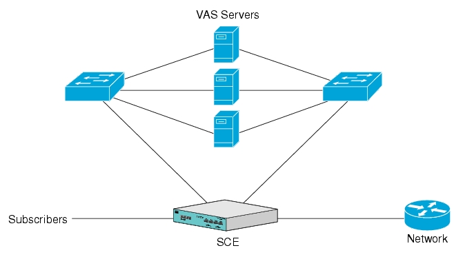
Important information:
A single SCE platform can support up to eight VAS servers.
A maximum of 512 SCE platforms can be connected.
The same VAS server may be used by more than one SCE platform.
The VAS traffic forwarding feature is supported on the SCE 2000 4xGBE platform only.
The following sections provide a more detailed description of the following aspects of VAS traffic forwarding:
VLAN tags for VAS traffic forwarding
VAS data flow
Load balancing
When VAS traffic forwarding is enabled, in addition to all its basic functions, the SCA BB application classifies each flow as either a VAS flow or as a standard flow (non-VAS flow). This classification is made on the first packet of the flow (e.g. TCP SYN packet). The classification must be performed on the very first packet since the classification is used to select the routing of the packet to a VAS server or to the subscriber/network.
VAS traffic forwarding rules are configured through the SCA-BB console. These rules map certain traffic to the VAS Server Groups. When a flow is classified as a VAS flow, the VAS Server Group for this flow is selected. If the group includes more than one VAS server, traffic will be forwarded in such a way that the subscriber load is shared between the servers on the same group.
The mapping of traffic portions to VAS Server Groups is done through the standard SCA GUI, this definition is given per package
The traffic is routed between the SCE platform and the VAS servers by VLANs. There is a unique VLAN tag for each SCE platform/VAS server combination.
Before being forwarded to the VAS servers, the SCE platform adds the VLAN tag to the original traffic. When the traffic returns to the SCE platform, the SCE platform removes the VLAN tag it previously added, and then forwards the traffic on its original link.
The VLAN tag to be used for each VAS server is configured by the user. To preserve consistency of the traffic flow, the VAS solution requires the user to configure a unique VLAN tag for each SCE platform/VAS server combination.
The VLAN tag format is shown in the figure below.

The VLAN tag has twelve bits, divided as follows:
The lower three bits identify the VAS server.
The higher nine bits identify the SCE platform.
For example:
0x20 = 100 000 = SCE #4, VAS #0
0x21 = 100 001 = SCE #4, VAS #1
0x58 = 1101 000 = SCE #13, VAS #0
Observe the following for the nine bits that identify the SCE platform:
These nine bits must be the same for all VAS servers attached to a specific SCE platform.
These nine bits must be different for VAS servers attached to different SCE platforms.
Examples of valid VLAN tag ranges for an SCE platform:
0x20, 0x21 – 0x27, but not 0x33
0x58,0x59 – 0x5F, but not 0x26
The SCE platform enforces that the VLAN tags configured by the user keep this format, meaning that the lower three bits match the VAS server number for which the VLAN tag is configured and that the higher nine bits match the higher nine bits previously configured for other VAS servers on this SCE platform. However, the SCE platform is not aware of the configuration of other SCE platforms, and therefore it is the responsibility of the user to configure a unique nine bits (SCE id) for each SCE platform.
Note that the use of VLAN tags is an integral part of the VAS solution, and therefore requires the VAS device to be able to work in 802.1q trunk while preserving the VLAN information.
The mapping of traffic portions to VAS Server Groups is done through the standard SCA GUI, this definition is given per package.
The SCE platform classifies a flow to a VAS Server Group based on the subscriber package and the TCP/UDP ports of the flow. It then selects one server within this group to handle the flow.
The SCE platform performs load sharing between multiple VAS servers belonging to the same Server Group; the balance is based on subscriber load. In other words, the SCE platform ensures that the subscribers are evenly distributed between the VAS servers in the same group. Note that the mapping of subscriber to a VAS server (per group) is kept even when servers are added or removed from the group either due to configuration changes or changes in the operational status of the servers in the group. The mapping will change only if the same server changes its status.
The following paragraphs explain in more details when and how the mapping is changed.
In a deployment using VAS traffic forwarding, there are two types of data flows:
Non-VAS flow
VAS flow
The following figure depicts the two types of data flows running through a single SCE platform and a single VAS server.
Ports are illustrated as two uni-directional half ports, RX (on the left side) and the TX (on the right side).
The SCE platform has four ports.
The VAS server has two ports.
For the sake of illustration, the SCE platform traffic flow direction is left to right while the VAS traffic flow is right to left. The arrow below the name of the element indicates the traffic flow direction.
The Ethernet switches are omitted.
Each line represents a flow
Thick line is a non-VAS flow
Thin line is a VAS flow
Black line indicates part of a flow that does not have VLAN tag
Red line indicates part of a flow that has a VLAN tag
This figure illustrates the data flow from the subscriber to the network. Data flow from the network to the subscriber works in exactly the same way, but is received on the network port (N) and transmitted on the subscriber port (S).
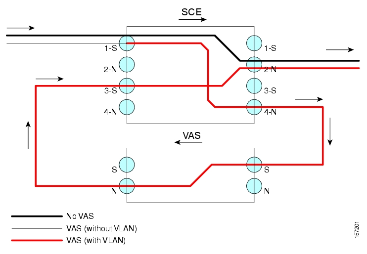
The flow steps for a non-VAS flow are:
A subscriber packet is received at the SCE platform port 1 (S).
The SCE platform classifies the flow as non-VAS flow.
The packet is sent to the network on port 2 (N).
VAS data flow is slightly more complex than the basic data flow. It is received and transmitted in the same manner as the basic non-VAS SCE platform flow, but before it is transmitted to its original destination, it flows through the VAS server.
The flow steps are:
A subscriber packet is received at the SCE platform port 1 (S).
The SCE platform classifies the flow as VAS flow.
The SCE platform adds a VLAN tag to the packet. The VLAN tag is used by the Ethernet switch to route the packet to the proper VAS server.
Note that at this point the packet has a VLAN tag, which is indicated by the red line.
The packet is sent to the VAS subscriber port from SCE platform port 4 (N).
The VAS server processes the packets and either drops the packet or sends it back to the SCE platform; from the VAS network port to the SCE platform subscribers port 3 (S).
Note that the VAS server passes the VLAN tag transparently. This is important to enable the Ethernet switch (not shown) to route the packet back to the proper SCE platform.
The SCE platform receives the packet on port 3 (S), drops the VLAN tag, and passes the packet towards the network through port 2 (N).
VAS servers can be grouped logically according to their service type. Consider, for example, a system that requires both FTP caching and virus filtering. A single VAS server for each service might not have enough capacity. Let us say that the system requires five VAS servers, three to provide FTP caching, and two to provide virus filtering. Defining two VAS Server Groups, FTP caching and virus filtering, permits load sharing across the servers for each Server Group.
The VAS Server Group to which the flow should be attached is determined by the package of the subscriber. The selection of a specific VAS server from the VAS servers within this group is based on the current load on each VAS server. The system tries to create an equal subscriber load for all the VAS servers belonging to the same group.
In some cases, a VAS server may be used by more than one SCE platform. Remember that the SCE platform performs load balancing only on the traffic that it sends to the VAS server; it is not aware how much of a load the VAS server may be bearing from a different SCE platform. It is the responsibility of the user to allocate available VAS servers to the SCE platforms in a way that ensures proper total load on each VAS server.
The system balances the usage of the VAS servers within a VAS Server Group, trying to create an equal subscriber load for all the VAS servers in one VAS Server Group. The load balancing is subscriber based, meaning that the subscribers are evenly distributed between the servers.
VAS load sharing is subscriber-based rather than bandwidth-based in order to ensure that all the traffic of the subscriber gets to the same server so the server can make subscriber based decisions.
The SCE platform uses the same VAS server for all the traffic of a subscriber (per server group) even if there is a change in the number of active servers in the group. Traffic from a subscriber is assigned to a new server only if the current server becomes inactive. This will only apply on new flows. Flows that were already mapped to a server before it became active will remain attached to it.
The mapping of subscriber to VAS servers not is saved across logouts or SCE platform reload.
Since the load balancing is subscribers based, this solution will not work properly in subscriberless mode, as the entire traffic load would be carried only by one VAS server per group.
Note
Use anonymous mode rather than subscriberless mode with VAS traffic forwarding.
In Pull mode, the first flow of the subscriber behaves as configured in the anonymous template. If no anonymous template is configured, such first flows will be processed as defined by the default template. Therefore, the default template should provide a proper package, so these flows will get VAS service.
The services provided by the VAS servers should be highly available. The failure of a single VAS server should not degrade the total system performance and availability. This requirement must be considered when determining the number of VAS servers necessary for each VAS service.
There are two mechanisms by which the system guarantees the performance and availability of the VAS services:
Load sharing — The SCE platform distributes the subscribers between all the active VAS servers within a server group
Monitoring — The SCE platform monitors connectivity with the VAS servers and handles server failure according to the applied configuration.
In addition to failure of an individual VAS server, a complete VAS Server Group is considered to be failed if a defined minimum number of servers are not active.
The system monitors the health of a VAS server by periodically checking the connectivity between the SCE platform and the VAS server. When the SCE platform fails to establish or maintain a connection to the server within a configurable window of time, the state of the server is considered to be Down.
The implications of such state are:
New logged-in subscribers will be distributed between the other active servers in the group.
Subscribers that are mapped to this server will be mapped to a new server if they initiate a new flow.
The Server Group may move to a Failure state if this failure caused the number of active servers in the group go below the minimum configured.
If the connectivity to the server resumes, the state of the server is changed to Up. The server returns to the list of active servers and will continue to serve subscribers that were mapped to it before the failure and have not yet been mapped to a new server during the failure time, as well as new subscribers.
For each VAS Server Group, the user can configure the following:
The minimum number of active servers necessary.
The action to take in case the actual number of active servers goes below this number.
Note that if the minimum number equals the total number of configured servers, it means there is no redundancy and failure of one server will cause the failure of the whole server group.
When the SCE platform detects that the number of active servers within a group is below the configured minimum, it changes the state of the group to Failure. The configured action-on-failure will then be applied to all new flows mapped for that VAS Server Group (existing flows will not be affected.)
There are two possible actions when the VAS Server Group has failed:
Block — all new flows assigned to the failed VAS Server Group will be blocked by the SCE platform.
Pass — all new flows assigned to the failed VAS Server Group will be considered as regular non-VAS flows, and will be processed without VAS service (that is, they will get SCA BB service but not VAS service).
When the number of active servers is above the minimum and the state of the group is changed to Active again, the configured action-on-failure is no longer applied to new flows. However, to maintain the coherency of the network, flows that were Blocked or Passed are not affected by the change in the state of the Server Group.
The Ethernet switches are a single point of failure in the VAS topology. A complete failure of an Ethernet switch causes all the VAS services to be declared as failed and the configured action (on-failure) will be taken for all new VAS flows.
A VAS server can be disabled for maintenance via the CLI.
No errors are reported on a disabled VAS server. However, if disabling the server reduces the number of active servers to below the minimum number configured for the group, it will bring down the VAS Server Group since a disabled VAS server is equal to a VAS server in a Down state.
Health check is not performed on disabled VAS servers.
In order to manage the VAS redundancy, the SCE platform needs to know the state of each VAS server. The SCE platform performs periodic health checks for all the configured VAS servers. These checks are the basis for VAS redundancy control; they enable the SCE platform to identify and react to VAS server failure, and to check the connectivity of the SCE platform-VAS server before enabling the server to handle traffic.
The health check is performed over the VAS link, the link that connects the SCE platform with the VAS servers. It validates the traffic flow between the SCE platform and the VAS server in both directions through special health check packets generated by the SCE platform.
The health check mechanism does not require special interaction with the VAS device, since the VAS server does not need to answer the health check packets, only to pass them as they are back to the SCE platform. As long as the packets are received by the SCE platform, the VAS server is considered to be alive. Failing to receive the packets back from the VAS server within a pre-defined time window is considered by the SCE platform as a failure of the VAS server and the server status is changed to Down.
Important information about the health check packets:
They are carried over UDP flows
Their source and destination IP addresses are configurable by the user
IP addresses should be:
Unique to the SCE platform
Addresses that will not be used by the network traffic (such as private IPs)
The SCE platform uses default UDP ports between 63140 and 63155, unless the user has configured different ports for the health check.
The SCE platform adds its own layer 7 data on top of the UDP transport layer. This data is used by the SCE platform to validate the correctness of the packet upon retrieval.
The health check is performed under the following conditions:
VAS mode is enabled
VAS server is enabled
Health Check for the VAS server is enabled
Server has VLAN tag
Pseudo IPs are configured for the GBE interfaces
If the check is enabled, but any one of the conditions is not met, the server state will be Down (the same as if the server did not pass the health check).
In order to check the connectivity with the VAS server before enabling it to handle traffic, the server should not be assigned to any group.
The health check procedure does not require a special interface with the VAS server, the health check traffic goes through the same network channels as any other VAS traffic. However, there are two assumptions the VAS servers should fulfill:
The VAS server does not drop traffic unless it is specifically configured to do so. Therefore, if the VAS server-SCE platform connectivity is operative, the health check packets should reach the SCE platform safely.
Alternatively, it should be able to configure the VAS server to pass traffic on specific ports (the health check ports).
In case of a failure, the VAS server should drop, not bypass, the traffic (cut the link), so that the SCE platform will be able to identify the failure.
When determining whether a VAS server is active, the system considers the following two parameters:
Admin mode as configured by the user — Enabled or disabled
VAS server state as reported by the health check
A VAS server may be in either of the following states:
UP — The server is UP if:
Health check disabled ¾ if the server is enabled, has a VLAN tag, and belongs to a group.
Health check enabled - if the server passes the health check
DOWN — The server is Down if the above conditions are not met.
A server is considered to be Active when its admin mode is Enable and its state is Up.
The following sections describe the following VAS traffic forwarding topologies:
Single SCE platform, many VAS servers
Many SCE platforms, many VAS servers
VAS over 10G, which is a special case of Cisco Multi-Gigabit Service Control Platform (MGSCP) solution, supporting only one external 10G link and using a Cisco 6500/7600 Series router as a dispatcher to distribute the external 10G link and as the switch towards the VAS servers.
Note
A topology in which a VAS server is directly connected to the SCE platform is not supported. If a topology of a single SCE platform connected to a single VAS server is desired, a switch should still be used between the SCE platform and the VAS server.
In this topology, a single SCE platform is forwarding VAS traffic to one or more VAS servers through two Ethernet switches.
The two Ethernet switches are necessary in order to avoid a situation in which a single MAC address has two ports or a single VLAN tag has two destinations. Each Ethernet switch should be configured to trunk mode with MAC learning disabled.
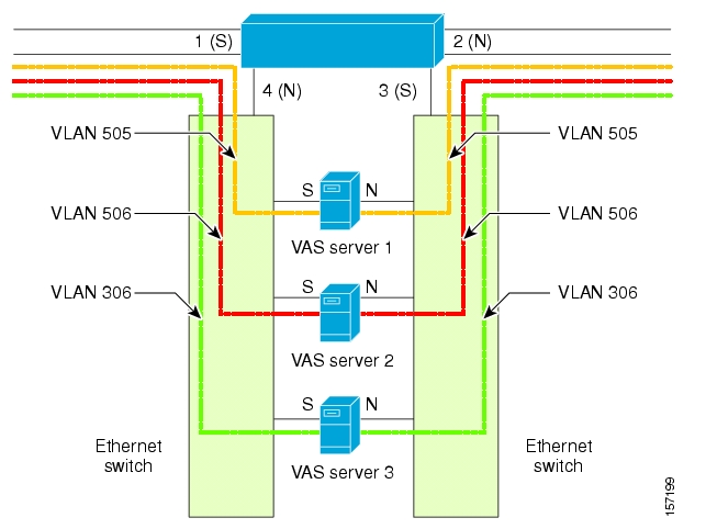
The data flow is:
A subscriber packet is received at port #1 (Subscriber).
The SCE platform opens a flow and classifies the flow as either a non-VAS (blue) flow or as a VAS flow (red).
If the flow is non-VAS (blue), the SCE platform passes the packet to the network. The VAS server is not involved in this case.
If the flow is a VAS flow (red), the SCE platform selects the VAS server to which the packet should be sent, adds the server VLAN tag to the packet and transmits the packet on port #4 (Network).
The packet is routed by the Ethernet switch to the VAS server according to its VLAN tag (the port towards the VAS server should be the only port with this VLAN tag allowed).
The VAS server processes the packet and either drops or forwards it without changing the VLAN tag.
The packet is forwarded by the Ethernet switch to the SCE platform according to its VLAN tag (the port towards the SCE platform should be the only port with this VLAN tag allowed).
The SCE platform receives the packet on port #3 (Subscriber), strips the VLAN tag and forwards the packet to the network via port #2 (Network).
In this topology, multiple SCE platforms are connected to multiple VAS servers. Note that at least one VAS server receives traffic from more than one SCE platform; if the VAS servers are each in an exclusive relationship to a particular SCE platform, it would simply be several single SCE platform/multiple VAS server topologies grouped together.
In the following figure, the top SCE platform forwards traffic to VAS servers 1 and 2, while the bottom SCE platform forwards to VAS servers 2 and 3. A unique VLAN tag must designate each SCE-platform-to-VAS-server path. This topology is illustrated with two SCE platforms, but a maximum of 512 SCE platforms is supported (limited by the VLAN tag size).
The two Ethernet switches route the traffic to the VAS servers. The routing is VLAN based. The Ethernet switch should be configured to trunk mode with learning disabled.
The data flow is the same as that for the previous topology.
Note that SCE platform redundancy on the cascade ports is not supported in this topology.
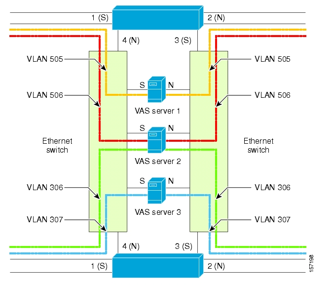
SCOS 3.0 adds the following items to the “PCUBE-SE-MIB” proprietary MIB:
SCE-MIB object: vasTrafficForwardingGrp
SCE-MIB Object type: vasServersTable - provides information on each VAS server operational status.
SNMP Trap: vasServerOperationalStatusChangeTrap - signifies that the agent entity has detected a change in the operational status of a VAS server.
There are three broad aspects to VAS traffic forwarding configuration in the SCE platform:
Configuring global VAS traffic forwarding options, such as enabling or disabling VAS traffic forwarding, or specifying the VAS traffic link.
Configuring a VAS server, such as enabling or disabling a specific VAS server, or enabling or disabling the VAS health check for a specified VAS server.
Configuring a VAS server group, such as adding or removing a specific VAS server, configuring the minimum number of active servers per group, or configuring VAS server group failure behavior.
Note
Additional VAS traffic forwarding configuration and monitoring options are available from the SCAS BB Console. See Managing VAS Traffic Forwarding Settings in the Cisco Service Control Application for Broadband User Guide.
Configure the SCE platform ¾ define the servers and the server groups, configure Pseudo IP for the GBE interfaces, and enable VAS mode.
Verify the state of the individual VAS servers as well as that of the VAS Server Groups to make sure all are Up (see Monitoring VAS Traffic Forwarding).
Configure which traffic goes to which Server Group through the SCA BB console (see Configuring VAS Traffic Forwarding from the SCA BB Console).
Configuration of the VAS Traffic Forwarding solution is distributed between the SCA BB console and the SCE platform CLI:
SCE platform CLI configuration:
Physical VAS server parameters — VLAN tag, Admin status and health check parameters
VAS server groups parameters — the VAS servers that belong to the group and the action to take if the group enters a failure state
SCA BB console configuration — the traffic forwarding rules, meaning which portion of the subscriber traffic should be forwarded to the VAS servers.
This configuration is defined per package so different subscribers can receive different VAS service, based on the package they bought.
There are two global VAS traffic forwarding options:
Enable or disable VAS traffic forwarding
Configure the link number on which to transmit VAS traffic (necessary only if the VAS servers are connected on link 0, rather than link 1, which is the default VAS traffic link))
By default, VAS traffic forwarding is disabled. If VAS traffic forwarding is required, the user must enable it.
For instructions on how to disable VAS traffic forwarding, see Disabling VAS Traffic Forwarding.
There are certain other SCE platform features that are incompatible with VAS traffic forwarding. Before enabling VAS traffic forwarding, it is the responsibility of the user to make sure that no incompatible features or modes are configured.
The features and modes listed below cannot coexist with VAS mode:
Line-card connection modes — receive-only, receive-only-cascade, inline-cascade
Link mode other than forwarding
All link encapsulation protocols, including VLAN, MPLS, L2TP
Enhanced open flow mode
The following options are available:
Enable/disable — Enable or disable VAS traffic forwarding
Default — Disable
Disabling the VAS Traffic Forwarding feature in runtime must be done with special care. There are two points to consider:
You cannot disable VAS mode in the SCE platform while the applied SCA BB policy instructs the SCE platform to forward traffic to the VAS servers.
Therefore, you must dismiss all VAS Traffic forwarding rules in the applied SCA BB policy before disabling the VAS traffic forwarding in the SCE platform.
After the SCA BB has been reconfigured, there may still be some open flows that have already been forwarded to the VAS servers. If the VAS feature is stopped while there are still such flows open, their packets coming back from the VAS servers may be routed to their original destination with the VLAN tag of the VAS server on it.
Therefore, it is also highly recommended to shutdown the line card before you disable the VAS traffic forwarding in the SCE platform to avoid inconsistency with flows that were already forwarded to the VAS servers.
To disable VAS traffic forwarding, complete the following steps
From the SCAS BB console, remove all the VAS table associations to packages and apply the changed policy.
Shutdown the line card:
Execute the CLI command
shutdownfrom the LineCard Interface Configuration mode.Disable VAS traffic forwarding:
Execute the CLI command
no VAS-traffic-forwardingfrom the LineCard Interface Configuration mode.Re-enable the line card:
Execute the CLI command ‘no shutdown’ from the LineCard Interface Configuration mode.
By default, the VAS traffic is transmitted on Link 1. If the VAS servers are connected on Link 0, you must configure the VAS traffic link to Link 0.
To configure the link for VAS over 10G, see Configuring the VAS Traffic Link (VAS over 10G).
Note
The VAS traffic link should be in Forwarding mode.
The following option is available:
VAS traffic-link {link-0|link-1} — The link number on which to transmit VAS traffic
Default — Link 1
The user must define the VAS servers. Each VAS server has the following parameters:
Admin-mode — Enabled or disabled.
Health Check mode — Enabled or Disabled
Health Check ports
VLAN tag
Use the following commands to perform these operations for individual VAS servers:
Enable a specified VAS server
Disable a specified VAS server
Define the VLAN tag for a specified VAS server
Enable or disable the Health Check for a VAS server
Define the source and destination ports to use for the Health Check.
Delete all properties for a specified VAS server. The server returns to the default state, which is enabled. However, it is not operational since it does not have VLAN.
Note that a VAS server is not operational until the VLAN tag is defined, even if the server itself is enabled.
Use this command to enable a VAS server.
To enable a VAS server, use the following command (note that the server is not operational until a VLAN tag has also been defined):
From the
SCE(config if)#prompt, typeVAS-traffic-forwarding VAS server-id<number> enableand press Enter.
Use this command to assign the VLAN ID to a specified VAS server.
The following options are available:
<VLAN-id>
—The VLAN tag to use for the specified VAS serverThe VLAN tag can be redefined as necessary.
Default — No VLAN.
Note the following important points:
The VAS server is not operational until the VLAN tag is defined.
Disabling the server does not remove the VLAN tag number configured to the server.
The no form of the command (same as the default form of the command), removes the previously configured VLAN tag (no VLAN is the default configuration).
Use these commands to enable and disable the Health Check, and to define the ports it should use.
By default, the VAS server health check is enabled, however the user may disable it.
Note that the health check will be activated only if all the following conditions are true. If the health check is enabled, the server state will be Down if one or more conditions are not met:
VAS Traffic Forwarding mode is enabled
Pseudo IPs are configured for the SCE platform GBE ports on the VAS traffic link
VAS server is enabled
Server has a VLAN tag
Health check for the server is enabled
To configure VAS server health check for VAS over 10G, see also Configuring Health Check for VAS over 10G.
If the health check of the server is disabled, its operational status depends on the following (requirements for Up state are in parentheses):
admin status (enable)
VLAN tag configuration (VLAN tag defined)
group mapping (assigned to group)
The following options are available:
VAS server-id <number> — The ID number of the VAS server for which to enable or disable the health check
Enable/disable — Enable or disable VAS server health check
Default — Enable
UPD ports — Specify the UDP ports to be used for the health check:
source <port number> — health check source port number
destination <port number> — health check destination port number
Default — <63140,63141> used for server #0 through <63154,63155> used for server #7.
To disable VAS server health check, use the following command:
From the
SCE(config if)#prompt, typeno VAS-traffic-forwarding VAS server-id<number> health-checkand press Enter.
To define the UDP ports to be used for the health check, use the following command
From the
SCE(config if)#prompt, typeVAS-traffic-forwarding VAS server-id<number> health-check UDP ports source <port number> destination <port number>and press Enter.
To remove the UDP port configuration, use the following commands
From the
SCE(config if)#prompt, type either of the following commands and press Enter:no VAS-traffic-forwarding VAS server-id<number> health-check UDP portsdefault VAS-traffic-forwarding VAS server-id<number> health-check UDP ports
Use this command to configure source and destination pseudo IP address for the health check packets. This command allows you to specify a unique IP address to be used by the health check packets.
This is a ROOT level command and is available under the GBE configuration interface mode. The interfaces that should be configured are those interfaces which connect the SCE platform with the VAS servers (by default interfaces GBE 0/3 and GBE 0/4).
The SCE platform uses the pseudo IP as follows:
Pseudo IP configured for the subscriber side interface:
source IP address for health check packets going in the Upstream direction
destination IP address for health check packets going in the Downstream direction
Pseudo IP configured for the network side interface:
source IP address for health check packets going in the Downstream direction
destination IP address for health check packets going in the Upstream direction
Note
This command is a ROOT level command in the Gigabit Interface Configuration mode.
The following options are available:
ip address — IP address to be used (any IP address as long as it is not possible to be found in the network traffic, such as a private IP)
Default — no IP address
subnet mask — Defines the range of IP addresses that can be used by the SCE platform. Note that the SCE platform is not required to reside in this subnet.
Default — 255.255.255.255 (The subnet mask can be set to 255.255.255.255, as the health check mechanism requires only one IP address per interface.)
The user may define up to eight VAS server groups. Each VAS server group has the following parameters:
Server Group ID
A list of VAS servers attached to this group.
Failure detection — minimum number of active servers required for this group so it will be considered to be Active. If the number of active servers goes below this minimum, the group will be in Failure state.
Failure action — action performed on all new data flows that should be mapped to this Server Group while it is in Failure state.
Options:
block
pass
Use the following commands to perform these operations for a VAS server group:
Add or remove a VAS server to or from a specified group.
Configure the minimum number of active servers for a specified group.
Configure failure behavior for a specified group.
Use these commands to add and remove servers to or from a specified VAS server group.
The following options are available:
group-number — The ID number of the VAS server group
id-number — The ID number of the VAS server
To add a VAS server to a specified VAS server group, use the following command:
From the
SCE(config if)#prompt, typeVAS-traffic-forwarding VAS server-groupgroup-numberserver-idid-numberand press Enter.
Use the following commands to configure these failure parameters for the specified VAS server group:
Minimum number of active servers — If the number of active servers in the server group goes below this number, the group will be in Failure state
Failure action — The action to be applied to all new flows mapped to this server group while it is Failure state:
Block — all new flows assigned to the failed VAS server group will be blocked by the SCE platform.
Pass — all new flows assigned to the failed VAS server group will be considered as regular non-VAS flows, and will be processed without VAS service.
The following options are available:
VAS server-group <number> — The ID number of the VAS server group
minimum-active-servers <number> — The minimum number of active servers required for the specified server group
Default — 1
failure action
—Which of the following actions will be applied to all new flows for the specified server group:block
pass (default)
To configure the minimum number of active servers for a specified VAS server group, use the following command:
From the
SCE(config if)#prompt, typeVAS-traffic-forwarding VAS server-group<number> failure minimum-active-servers <number>and press Enter.
To reset the minimum number of active servers for a specified VAS server group to the default value, use the following command:
From the
SCE(config if)#prompt, typedefault VAS-traffic-forwarding VAS server-group<number> failure minimum-active-servers <number>and press Enter.
Use these commands to display the following information for VAS configuration and operational status summary.
Global VAS status summary — VAS mode, the traffic link used
VAS Server Groups information summary — operational status, number of configured servers, number of current active servers.
This information may be displayed for a specific server group or all server groups
VAS servers information summary — operational status, Health Check operational status, number of subscribers attached to this server.
This information may be displayed for a specific server or all servers
Bandwidth per VAS server and VAS direction (to VAS / from VAS)
VAS health check counters
Sample outputs are included.
Note
All the following CLI commands are viewer commands. If in line interface configuration mode, you must exit to the privileged exec mode and see the SCE# prompt displayed
To display global VAS status and configuration, use the following command:
From the
SCE#prompt, typeshow interface linecard 0 VAS-traffic-forwardingand press Enter.Sample output:
VAS traffic forwarding is enabled
VAS traffic link configured: Link-1   actual: Link-1
To display operational and configuration information for a specific VAS Server Group, use the following command:
From the
SCE#prompt, typeshow interface linecard 0 VAS-traffic-forwarding VAS server-group<number>and press Enter.Sample output:
VAS server group 0:
State: Failure  configured servers: 0   active servers: 0
minimum active servers required for Active state: 1   failure action: Pass
To display operational and configuration information for all VAS Server Groups, use the following command:
From the
SCE#prompt, typeshow interface linecard 0 VAS-traffic-forwarding VAS server-group alland press Enter.
To display operational and configuration information for a specific VAS server, use the following command:
From the
SCE#prompt, typeshow interface linecard 0 VAS-traffic-forwarding VAS server-id<number>and press Enter.Sample output:
VAS server 0:
Configured mode: enable   actual mode: enable   VLAN:  520  server group:    3
State: UP
Health Check configured mode: enable  status: running
Health Check source port: 63140  destination port: 63141
Number of subscribers:       0
To display operational and configuration information for all VAS servers, use the following command:
From the
SCE#prompt, typeshow interface linecard 0 VAS-traffic-forwarding VAS server-id alland press Enter.
To display the VAS servers used by a specified subscriber per VAS Server Group, use the following command:
From the
SCE#prompt, typeshow interface linecard 0 subscriber name<subscriber-name> VAS-serversand press Enter.
To display health check counters for a specific server, use the following command:
From the
SCE#prompt, typeshow interface linecard 0 VAS-traffic-forwarding VAS server-id<number> counters health-checkand press Enter.Sample output
Health Checks statistics for VAS server '0'    Upstream      Downstream
------------------------------------------------------------------------
Flow Index '0'
-----------------
Total packets sent                         :       31028  :       31027 :
Total packets received                     :       31028  :       31027 :
Good packets received                      :       31028  :       31027 :
Error packets received                     :           0  :           0 :
Not handled packets                        :           0  :           0 :
Average roundtrip (in millisecond)         :           0  :           0 :
Error packets details                      :              :             :
---------------------                      :              :             :
Reordered packets                          :           0  :           0 :
Bad Length packets                         :           0  :           0 :
IP Checksum error packets                  :           0  :           0 :
L4 Checksum error packets                  :           0  :           0 :
L7 Checksum error packets                  :           0  :           0 :
Bad VLAN tag packets                       :           0  :           0 :
Bad Device ID packets                      :           0  :           0 :
Bad Server ID packets                      :           0  :           0 :
To display health check counters for all servers, use the following command:
From the
SCE#prompt, typeshow interface linecard 0 VAS-traffic-forwarding VAS server-id all counters health-checkand press Enter.
To clear health check counters for a specific server, use the following command:
From the
SCE#prompt, typeclear interface linecard 0 VAS-traffic-forwarding VAS server-id<number> counters health-checkand press Enter.
To clear health check counters for all servers, use the following command:
From the
SCE#prompt, typeclear interface linecard 0 VAS-traffic-forwarding VAS server-id all counters health-checkand press Enter.
To display bandwidth per VAS server and VAS direction, use the following command:
From the
SCE#prompt, typeshow interface linecard 0 counters VAS-traffic-bandwidthand press Enter.
Note that the bandwidth presented in this command is measured at the Transmit queues, therefore the first table in the following output sample presents the bandwidth of traffic transmitted towards the VAS servers and the second table presents the bandwidth of traffic transmitted out of the SCE platform after being handled by the VAS servers. Note that the counting is based on L2 bytes.
Sample output
Traffic sent to VAS processing TxBW [Kbps] (bytes are counted from Layer 2):
       Port 1 Port 2 Port 3 Port 4
 -------- -------- -------- --------
VAS server id 0: 0 0 0 0
VAS server id 1: 0 0 0 0
VAS server id 2: 0 0 0 0
VAS server id 3: 0 0 0 0
VAS server id 4: 0 0 0 0
VAS server id 5: 0 0 0 0
VAS server id 6: 0 0 0 0
VAS server id 7: 0 0 0 0

Traffic after VAS processing TxBW [Kbps] (bytes are counted from Layer 2):
        Port 1 Port 2 Port 3 Port 4
 -------- -------- -------- --------
VAS server id 0: 0 0 0 0
VAS server id 1: 0 0 0 0
VAS server id 2: 0 0 0 0
VAS server id 3: 0 0 0 0
VAS server id 4: 0 0 0 0
VAS server id 5: 0 0 0 0
VAS server id 6: 0 0 0 0
VAS server id 7: 0 0 0 0There are certain SCE platform features that are incompatible with VAS traffic forwarding. Before enabling VAS traffic forwarding, it is the responsibility of the user to make sure that no incompatible features or modes are configured.
The features and modes listed below cannot coexist with VAS mode are:
Line-card connection modes — receive-only, receive-only-cascade, inline-cascade
Link mode other than forwarding
All link encapsulation protocols, including VLAN, MPLS, L2TP
VAS traffic forwarding has the following minor effects on the DDoS mechanisms.
The specific IP DDoS mechanism uses software counters. The second pass VAS packets do not reach the software, so they are not counted twice.
Network side packetsare handled by the attack-detector in the first pass,when they open a flow, so they also are not counted twice.
The complexity of the VAS traffic forwarding results in the modification of some SCE platform bandwidth management capabilities when using this feature:
VAS flows are not subject to global bandwidth control.
The number of global controllers available to regular flows has been decreased from 64 to 48.
Certain changes are required in the configuration of the global controllers in order to support these two restrictions.
When VAS traffic forwarding is enabled, the global controllers function slightly differently.
Only 48 global controllers are available to the user.
Global controllers 49-63 are used to count VAS traffic.
The reserved global controllers cannot be configured.
On VAS flows, the flow does not get its global controller from the traffic controller to which it belongs. Rather, its global controller is set according to VAS rules.
A specific configuration of VAS traffic forwarding is VAS over 10G using a Cisco 6500/7600 Series router as a dispatcher. The VAS over 10G topology is a specific application of the Cisco Multi-Gigabit Service Control Platform (MGSCP) solution in which only one external 10G link is supported. The 7600 distributes the external 10G link and also functions as the switch for the VAS servers.
VAS functionality is supported over a dual 10G topology only. This topology provides a solution with no single point of failure.
In this topology, there are two external 10G links, each one connected to a separate 7600 platform and VAS server array. Only one set of VAS servers is used at a time, serving the VAS traffic of both 10G links. The other set of VAS servers is reserved for failover in case of either a switch failure or VAS server failure.
The following figure illustrates the VAS over 10G topology.
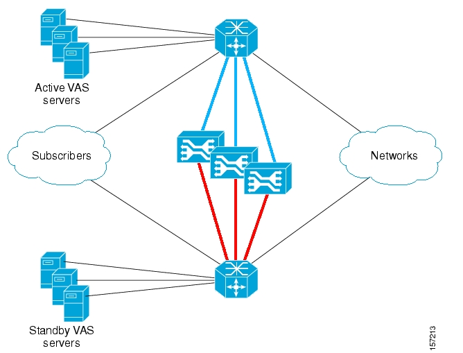
Data flow in the VAS solution over 10G topology depends on the appropriate use of VLAN tags to route the packets through the system, from the 7600/6500 to the SCE platform, to the appropriate VAS server, back to the SCE platform and then back to the network through the 7600/6500.
The following figure illustrates the flow of VAS data in the VAS solution over 10G topology. Note that the path between the SCE platform and the VAS servers has the same VLAN tag for all SCE platforms in the same EtherChannel.
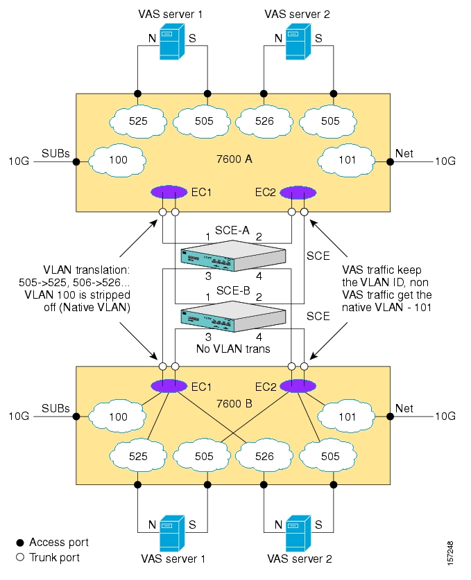
VAS flows enter the SCE platform without a VLAN tag, and are then transmitted from the SCE platform with the VLAN tag of the VAS server. They must return from the VAS server to the SCE platform with this tag, which is then stripped off.
In the solution using the 7600/6500, VLAN tags are also used to identify the external link. Note that this is not the same VLAN tag used for the VAS servers. This VLAN tag must be defined as native in the trunk ports towards the SCE platforms, so that the external traffic arrives at the SCE platform without a VLAN tag.
In this description of the VAS data flow, note the following important points:
This section describes the data flow of packets originating at the subscriber side of the 10G link and sent towards the network. The network to subscriber flow exactly mirrors this flow.
The description does not elaborate on the internal path inside the 7600/6500 device. It is intended to present the path between the SCE platform, the 7600/6500, and the VAS servers, and describe how the VLAN tag changes along that path.
Although the figures show only one SCE platform, in actuality the VAS over 10G topology would usually consist of multiple SCE platforms on multiple ECs. In such a topology, the ports towards the VAS servers must be trunk ports, which allow the presence of multiple VLAN tags, since there will be a unique VLAN tag for each EC. (As noted previously, all SCE platforms on one EC must use the same VLAN tag per VAS server).
The data flow is presented in two parts:
To the VAS servers
From the VAS servers
The figures assume that the VAS link is link 1.
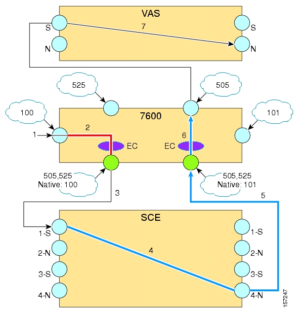
The following is the sequence of steps in the VAS data flow from the subscriber side to the VAS server:
A subscriber packet is received at the 7600/6500 external 10G link.
The packet is marked with VLAN 100 at the access port and is sent towards the EtherChannel (EC) configured with VLAN 100.
The EC selects port 1 of the SCE platform based on the subscriber side IP, and the VLAN tag is stripped off (100 is the native VLAN tag in the 7600/6500 trunk port).
The SCE platform classifies the flow as VAS flow and tags it with the VAS server VLAN tag 505.
The packet is sent to the VAS server from SCE platform port 2 (N) towards the 7600/6500 with VLAN tag 505.
The packet is received on the 7600/6500 trunk port and is sent to the access port configured with VLAN 505, which is the port connected to the VAS server subscriber side.
The packet has no VLAN tag when it arrives at the VAS server.
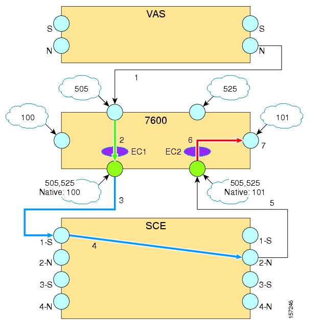
The following is the sequence of steps in the VAS data flow from the VAS server out to the network:
The VAS server processes the packet and sends it to the SCE platform from the VAS network port. Note that as the VAS server received the packet with no VLAN tag, it also transmits it with no VLAN tag.
The packet is received on the 7600/6500 access port, is assigned VLAN tag 525, and is sent towards the EC configured with VLAN 525.
At the trunk port, the VLAN tag 525 is translated to VLAN tag 505. The packet is sent towards port 1 of the SCE platform based on the subscriber side IP.
SCE platform gets the packet on port 1 (S) and forwards it towards the network through port 2 (N)
The SCE platform forwards the packet with NO VLAN tag.
The packet is received on the 7600/6500 trunk port, gets the native VLAN 101 and sent towards the access port configured with VLAN 101.
The packet is sent towards the network with no VLAN tag.
The SCE monitors the health of the connection to each VAS server on the active VAS link; failure of either the 7600/6500 or the VAS server will cause the server health check to fail. The failure of one or more server groups causes the VAS traffic to be forwarded to the redundant 7600/6500/VAS servers system.
How failover works:
The VAS link (the link on which to send the VAS traffic) is dynamically selected. In failover, the SCE platform switches to its backup subscriber and network ports, so that the VAS traffic is forwarded to the redundant set of VAS devices, as illustrated in the following figure.
The VAS link does not revert automatically. It will be switched again only if required due to a VAS server group failure on this link.
The system always checks only one set of the VAS servers; those on the active VAS link.
There is a user-configurable parameter that controls the link-switch rate if there has not been a successful health check on the current VAS link. The default value of this parameter is less than the failure detection time. It is recommended to configure a larger value.
Once there is a successful health check on the VAS link, the link switches immediately upon failure (see Configuring the Minimum Time between Link Switches).
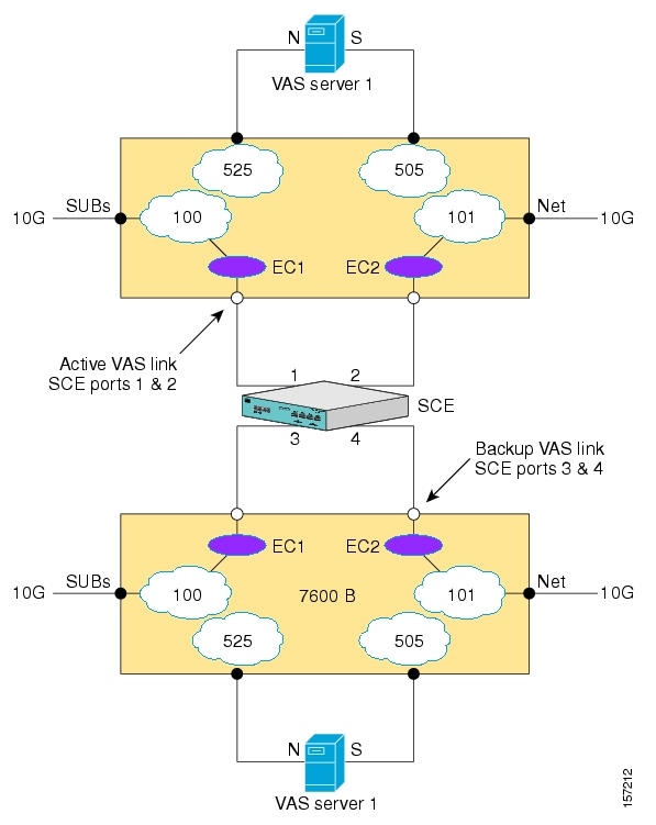
In the VAS over 10G topology, a failure may occur at any of the following three points:
Failure of an SCE platform
SCE platform failure is detected and handled by the 7600/6500 device. In such case, the EtherChannel will balance the traffic load between the other active SCE platforms.
SCA BB and VAS service through the other SCE platforms continues uninterrupted with no change in the VAS link.
Failure of a 7600/6500
The 10G link that goes through the failed 7600/6500 device is lost completely, however SCA BB and VAS services on the 10G link that goes through the second 7600/6500 device continue uninterrupted.
In case of failure of the 7600/6500 that is connected to the active set of VAS servers, all the VAS traffic of the other 10G link is forwarded to the standby set of VAS servers
Failure of a VAS server group
Failure of a VAS server group on the active VAS traffic link is detected by the VAS health check. Failure of any VAS server group triggers the switch of the entire link to the standby VAS servers. A server group failure is declared when the number of active VAS servers drops below the parameter “minimum active VAS servers in a group” (see Configuring VAS Server Group Failure Parameters).
Both links preserve SCA BB and VAS services. However, during the transition period, the replacing VAS servers will see VAS flows in the middle and the VAS service may be temporarily damaged.
In the VAS over 10G topology, special attention must be paid to the selected IP addresses of the health check flows. A flow initiated by an SCE platform may not always be hashed correctly by the EtherChannel. Therefore, a health check packet can be sent out from one SCE platform, go through the 7600/6500 towards the VAS server, then be sent back from the VAS server through the 7600/6500 but hashed by the EtherChannel to a SCE platform different than the originator SCE platform.
To prevent this from happening, the SCE platform opens eight flows per VAS server. This ensures that at least one of the flows will be mapped to the correct SCE platform; the other SCE platforms disregard health check packets not initiated by them.
When configuring VAS over 10G, the following changes must be made to the configuration process:
Configuration of the VAS traffic link is different (see Configuring the VAS Traffic Link (VAS over 10G))
You must configure a range of IP addresses as the source IP addresses for the health check (see Configuring the Health Check IP Address).
The health check must be specifically enabled to be compatible with the 10G topology (see Enabling the Health Check for VAS over 10G Topology).
Note
The VLAN tags and configuration of the two sets of VAS servers must be identical.
Note
Additional VAS traffic forwarding configuration and monitoring options are available from the SCAS BB Console. See Managing VAS Traffic Forwarding Settings in the Cisco Service Control Application for Broadband User Guide.
This section explains some important points to keep in mind when configuring the 7600/6500 as part of the VAS over 10G solution. For complete information on how to configure the 7600/6500, please refer to the appropriate Cisco documentation.
Please refer to the following guidelines when configuring the 7600/6500 as part of the VAS over 10G solution:
The 7600/6500 device traffic distribution is based on the EtherChannel dispatching function. Specifically it is required that:
External traffic coming from the subscriber side of the 7600/6500 device must be hashed by the EtherChannel according to the source IP
External traffic coming from the network side must be hashed according to the destination IP.
This requirement insures that the same SCE platform handles all the traffic of a subscriber. Since the hashing metric is configurable per line card, the external 10G link subscriber and network ports must be on different line cards. The VAS servers should be connected to the 7600/6500 following this convention as well:
Connect the VAS server subscriber leg to the same line card as the network 10G port, or to a line card that is configured with per destination IP dispatching function.
Connect the VAS server network leg to the same line card as the subscriber 10G port, or to a line card that is configured with per source IP dispatching function.
In order for the native VLAN configuration to be effective, disable the "vlan dot1q tag native" configuration on the 7600/6500.
Introduce the VLAN tags of the VAS servers and the external subscriber and Network ports by running the "vlan XXX" configuration command on the 7600/6500 device.
To enable switching the VAS traffic automatically upon a failover situation, the following options must be configured for VAS over 10G:
Set the VAS traffic link to auto-select, so that the system can switch between the links in case of 7600/6500/VAS servers failure.
Specify the minimum time allowed between two consecutive link switches before any health check has succeeded.
Specify the link on which to transmit VAS traffic initially after changing the configuration to ‘auto-select’ (in runtime or after reload) or the current VAS traffic link if ‘auto-select’ is already configured.
Note
All commands in this section are Interface LineCard Configuration commands
By default, the VAS traffic is transmitted on Link 1. However, for VAS over 10G, the VAS link should be set to auto-select, so that the system can switch to the backup link when necessary.
The following option is available:
VAS traffic-link {link-0|link-1|auto-select} — The link number on which to transmit VAS traffic
For VAS over 10G, specify auto-select.
You can configure the minimum time allowed between two consecutive link switches. This parameter applies only after a link switch and before any health check has succeeded.
Note that the system assumes the servers are UP while the health check initializes (initialization occurs as a result of every change in the configuration related to the health check or after a link switch, and it lasts until the first health check success or failure). This means that even if the servers are actually DOWN or not even connected, it is assumed that they are UP and user traffic is forwarded to them. Once the health check fails, the servers are declared to be Down, and user traffic is no longer forwarded to them.
In VAS over 10G topology, the default delay between two consecutive link switches (30 seconds) is less than the time it takes for the health check to fail. This means that once a VAS server group fails, the SCE platform switches immediately to the second link.
In cases where there is at least one failed VAS server group on both links, the SCE platform will flip continuously between the links, and as described above, most of this time the state of the servers will be UP.
To avoid the constant flip between the links in such a case, it is recommended to configure a link-switch-delay time greater than 3 minutes.
It is also recommended to monitor the SNMP traps conveying messages on changes in server status.
The following option is available:
switch-time — The time in seconds to hold between two consecutive link switches on initial health check state.
Default = 30 seconds
To configure the delay between two consecutive link switches, use the following command:
From the
SCE(config if)#prompt, typeVAS-traffic-forwarding traffic-link auto-select link-switch-delay<switch-time>and press Enter.
To revert to the default delay between two consecutive link switches, use either of the following commands:
From the
SCE(config if)#prompt, typeno VAS-traffic-forwarding traffic-link auto-select link-switch-delayand press Enter.From the
SCE(config if)#prompt, typedefault VAS-traffic-forwarding traffic-link auto-select link-switch-delayand press Enter.
Use this command to set the active VAS link, the link on which to transmit VAS traffic after a system reload and when working in auto-select mode.
When executed, this command triggers an immediate link switch if the currently active VAS traffic link used is different from the one specified in the command.
The following option is available:
initial-selection {link-0|link-1} — The link number to be set as the active VAS link.
Default = link-1.
To set the active VAS link, use the following command:
From the
SCE(config if)#prompt, typeVAS-traffic-forwarding traffic-link auto-select initial-selection {link-0 | link-1}and press Enter.
To set the active VAS link to the default values, use either of the following commands:
From the
SCE(config if)#prompt, typeno VAS-traffic-forwarding traffic-link auto-select initial-selectionand press Enter.From the
SCE(config if)#prompt, typedefault VAS-traffic-forwarding traffic-link auto-select initial-selectionand press Enter.
When configuring the health check for VAS over 10G, you must perform the following steps:
Configure the health check source and destination IP addresses
Enable health check compatibility for VAS over 10G
Note
All commands in this section are Interface LineCard Configuration commands.
Use this command to configure the IP addresses to be used for the VAS health check flows. Any traffic to the configured IP address will be handled as belonging to health check flows; it will not be processed as usual traffic and will be dropped by the SCE platform.
There are three important rules to follow when configuring the IP addresses of the VAS health check. Improper configuration will cause the health check to fail and may cause health check traffic to be forwarded outside of the 7600/6500.
It is required to configure a range of IP addresses (at least eight IP addresses) for the source IP. This will insure that at least one out of the eight flows will be hashed correctly to the SCE platform. If no range is configured and the VAS over 10G mode (MGSCP) is selected, the health check will fail to run.
The configured IP addresses must be unique to the SCE platforms and should not exist in the network. Any traffic to the configured IP addresses other than VAS health check traffic will be regarded as fault traffic and be dropped by the SCE platform.
All the SCE platforms under the same EtherChannel must have the same IP address configuration. Using the same IP addresses allows the SCE platform to correctly identify health check flows coming from other SCE platforms (as a result of the EtherChannel hashing) and drop these flows before they are transmitted out of the SCE platform.
Note
This command is permitted only when the linecard has been shutdown or no application is assigned.
The following options are available:
ip-address — Specify the IP addresses to be used for the health check:
source <source-ip> — health check source IP address
The source-ip must include a range indication (A.B.C.D/E or A.B.C.D:0xMASK, where A,B,C,D are numbers between [0,255] and E is in the range [0,32]. MASK is the IP mask in 8 hexadecimal characters.)
destination <dest-ip> — health check destination IP address
The configured IP addresses should not be in use in the network.
The same IP address should be used by all the SCE platforms under the same EtherChannel.
Use the no form to remove the configured IP addresses.
Use this command to configure the health check to adjust to VAS over 10G (MGSCP) conditions (see Health Check in VAS over 10G Topology).
The keyword MGSCP is specified to enable health check compatibility because VAS over 10G is a special case of a MGSCP (Multi-Gigabit Service Control Platform) system.
By default, VAS over 10G compatibility is disabled.
To enable health check compatibility for VAS over 10G (MGSCP), use the following command:
From the
SCE(config if)#prompt, typeVAS-traffic-forwarding health-check topology MGSCPand press Enter.
To disable health check compatibility for VAS over 10G (MGSCP), use either of the following commands:
From the
SCE(config if)#prompt, typeno VAS-traffic-forwarding health-check topology MGSCPand press Enter.From the
SCE(config if)#prompt, typedefault VAS-traffic-forwarding health-check topology MGSCPand press Enter.
Following is a sample illustrating the steps in configuring the VAS over 10G solution.
Enter the LineCard Interface configuration mode:
SCE(config)#interface LineCard 0Set VAS health-check to MGSCP mode:
SCE(config if)#VAS-traffic-forwarding health-check topology MGSCPSet VAS health-check source IP address to the range 192.168.100.0/24 and destination to 192.168.101.0:
SCE(config if)#VAS-traffic-forwarding health-check ip-address source 192.168.100.0:0xffffff00 destination 192.168.101.0Set VAS traffic link to auto-select so in case of a failure in any of the VAS servers group, the VAS traffic link will be automatically switched:
SCE(config if)#VAS-traffic-forwarding traffic-link auto-select
Configure the link switch delay to 4 minutes. The delay will be applied only if there was no successful health check on the current link:
SCE(config if)#VAS-traffic-forwarding traffic-link auto-select link-switch-delay 240.Set link-0 to be used as the initial VAS traffic link in auto-select mode:
SCE(config if)#VAS-traffic-forwarding traffic-link auto-select initial-selection link-0Assign VAS servers 0-3 to VLAN 600-603 respectively
SCE(config if)#VAS-traffic-forwarding VAS server-id 0 VLAN 600SCE(config if)#VAS-traffic-forwarding VAS server-id 1 VLAN 601SCE(config if)#VAS-traffic-forwarding VAS server-id 2 VLAN 602SCE(config if)#VAS-traffic-forwarding VAS server-id 3 VLAN 603Map VAS servers 0-1 and 2-3 to server groups 0 and 1 respectively, allowing server redundancy within each group:
SCE(config if)#VAS-traffic-forwarding VAS server-group 0 server-id 0SCE(config if)#VAS-traffic-forwarding VAS server-group 0 server-id 1SCE(config if)#VAS-traffic-forwarding VAS server-group 1 server-id 2SCE(config if)#VAS-traffic-forwarding VAS server-group 1 server-id 3The SCE platform is now set to forward VAS traffic:
SCE(config if)#VAS-traffic-forwarding
MPLS/VPN networks are very complex and contain many routing protocols and many different levels of addressing and control. In addition, the various VPNs may use overlapping IP addresses (private IPs).
The SCE platform makes a distinction between identical IP addresses that come from different VPNs, and maps them into subscribers according to the MPLS labels attached to the packets. This involves various mechanisms in all levels of the system.
The following assumptions and requirements allow the SCE platform to operate in an MPLS/VPN environment:
The MPLS/VPN architecture is according to RFC-2547.
The specific type of encapsulation used is the MPLS shim header over Ethernet (described in RFC-3032).
There are two levels of MPLS labels.
External labels — Used for transport over the service provider MPLS core network.
Internal labels (BGP labels) — Used to identify the VPNs connected to each edge router, and typically controlled by the BGP protocol.
All IP addresses in one VPN are treated as a single subscriber.
The MPLS/VPN solution contains the SCE platform and the SM. The SM acts as a BGP peer for the PE routers in the service provider network, and communicates the BGP information to the SCE platform as subscriber information.
Note
The MPLS/VPN solution supports the existence of non-VPN subscribers concurrently with the MPLS/VPN subscribers (see Non-VPN Subscribers).
Table 13.1. MPLS/VPN Terms and Acronyms
|
Term or Acronym |
Definition |
|---|---|
|
PE (Provider Edge router) |
A router at the edge of the service provider network. The PE routers are the ones that connect to the customers, and maintain the VPNs. |
|
P (Provider router) |
A router in the core of the service provider network. P routers only forward MPLS packets, regardless of VPNs. |
|
VPN (Virtual Private Network) |
In the Service Control context, a VPN is the part of the VPN that resides in a specific site. This is the subscriber of the solution. |
|
BGP LEG |
A software module that resides on the SM server and generates BGP-related login events. The BGP LEG communicates with the BGP routers (PEs) and passes the relevant updates to the SM software, which generates login events to the SCE platform for the updated VPN subscribers. |
|
Upstream |
Traffic coming from the PE router and going into the P router |
|
Downstream |
Traffic coming from the P router and going into the PE router |
|
RD (Route Distinguisher) |
Used to uniquely identify the same network/mask from different VRFs (such as, 10.0.0.0/8 from VPN A and 10.0.0.0/8 from VPN B) |
|
RT (Route Target) |
Used by the routing protocols to control import and export policies, to build arbitrary VPN topologies for customers |
|
VRF (Virtual Routing and Forwarding instance) |
Mechanism used to build per-interface routing tables. Each PE has a number of VRFs, one for each site it connects to. This is how the private IPs remain unique. |
Private IP addresses cause flows to look the same except for their MPLS labels.
The MPLS labels are different in each direction, and must be matched.
An entire VPN must be accounted as one subscriber. The problem is how to detect that a flow belongs to a certain VPN.
In the downstream direction there is no external label. We must be able to understand the VPN information from the internal label + the MAC address of the PE.
Service Control supports two mechanisms that make MPLS/VPN support work:
Flow detection – This is the job of the SCE platform, to match upstream and downstream traffic in order to identify flows.
Subscriber detection – This is the job of the SM, to match downstream labels with the VPN to identify the subscriber entity.
Flow detection is the process of deciding which packets belong to the same flow. This relates to the first two challenges listed:
Private IP addresses cause flows to look the same except for their MPLS labels.
The MPLS labels are different in each direction, and must be matched.
Flow detection is based on the MPLS labels, extending the basic 5 tuple that SCOS uses to identify flows, and taking into account the fact that in MPLS, the packet is labeled differently in each direction.
Since MPLS traffic is unidirectional, each direction is classified separately by the SCE platform, using the following:
Downstream – the BGP label and the MAC address of the PE (only one label that is relevant to the classification)
Downstream labels are learnt from the control plane (BGP).
Upstream – the combination of the external label, the BGP label, and the MAC address of the P router (two labels that are relevant to the classification)
Upstream labels are learnt from the data plane.
As in other modes of operation, in MPLS/VPN each flow belongs to a certain subscriber. A VPN subscriber is a customer of the Service Provider, who pays for the VPN service. All traffic of that VPN customer is aggregated into a single VPN subscriber for Service Control.
The network configuration that provides the division into VPN subscribers is controlled by the SM. The network-wide value that describes a VPN most closely is either the Route Target or the Route Distinguisher:
The administrator configures the SM to detect VPN subscribers, according to selected attribute (RT or RD) (see Configuring the SM for MPLS/VPN Support.)
The network operator provides the SCE platform with a mapping between RT values and VPN subscriber names. (See Managing Individual Subscriber MPLS/VPN Mappings.)
The relevant module in the Subscriber Manager server (SM) is the BGP-LEG. The BGP-LEG is added to the BGP neighborhood for obtaining the information on the MPLS labels. The local PEs are configured to add the BGP-LEG as a BGP peer.
BGP-LEG gets MP-BGP messages from the PEs with the allocated labels per VPN and forwards them to the SM module.
The SM updates each SCE platform with the mapping of MPLS labels to VPN subscribers.
The SM is configured with the VPNs that should be managed.
A VPN is identified by the RD / RT and the PE.
The BGP-LEG updates the SM with the MPLS labels.
The SM pushes the VPN subscriber to the SCE platform with the downstream MPLS labels of the VPN.
The SCE platform resolves the PE MAC addresses and updates its tables with the new information.
The SCE platform learns the upstream labels, including the P MAC address.
The SCE platform provides the regular services to the VPN subscriber (BW management, reports, etc.)
Matching upstream to downstream labels
Mappings of downstream labels to VPN subscribers are received from the SM
Upstream labels are learned from the data
The MAC addresses of the PEs are used in order to distinguish downstream labels of different PEs
After the learning period, each flow is classified as belonging to one of the VPN subscribers
The SCE platform runs the SCA-BB application for the network flows, which are classified to VPN subscribers, thus providing subscriber aware service control and reporting
The BGP LEG is a software module that runs on the SM server
The LEG maintains a BGP session with a list of PEs
After the sessions establishment, the LEG propagates MP-BGP route-updates from the PEs to the SM module
The VPNs are stored in the SM database as VPN subscribers.
A VPN subscriber is a group of VPN sites.
Each VPN site is defined by:
The IP address of the loopback interface of the PE router.
The RD or RT that identifies the VPN within the PE router.
The SM receives updates from the BGP LEG, and updates the VPN subscriber information with the new MPLS labels.
The relevant SCE platforms that will get the MPLS updates are defined by the VPN subscriber domain.
The MPLS/VPN solution supports the existence of non-VPN (regular IP) subscribers concurrently with the MPLS/VPN subscribers, with the following limitations and requirements:
The SM must work in "push" mode.
Non-VPN subscribers cannot have MPLS/VPN mappings.
VLAN subscribers are NOT supported at the same time as MPLS/VPN subscribers.
In typical MPLS/VPN networks, traffic that does not belong to any VPN is labeled with a single MPLS label in the upstream direction, which is used for routing. The downstream direction of such flows typically contains no label, due to penultimate hop popping.
The SCE platform uses the one or more labels upstream and no label downstream definition to identify non-VPN flows. Classification and traffic processor load balancing on these flows is performed according to the IP header, rather than the label.
This process requires learning of the upstream labels in use for such flows, and is done using the flow detection mechanism described above (see Flow Detection).
In an MPLS network, there may be many VPNs crossing the SCE platform, only a small number of which require service control functionality. It is necessary for the SCE platform to recognize which VPNs are not managed.
The SCE platform automatically bypasses any VPN that is not configured in the SM
The VPNs are bypassed by the SCE platform without any service
Note that the label limit of 57,344 different labels includes labels from the bypassed VPNs.
Each bypassed VPN entry, both upstream and downstream, is removed from the database after a set period of time (10 minutes). If the entry is still used in the traffic, it will be re-learnt. This allows the database to remain clean, even if the labels are reused by the routers for different VPNs.
In the show bypassed VPNs command, the age is indicated with each label - the length of time since it was learnt.
The MPLS/VPN solution was designed to provide DPI services in MPLS/VPN network. These networks use BGP protocol as the control plane for the VPNs and LDP protocol for routing. There are complex networks where the MPLS infrastructure is used not only for VPN and routing, but also for other features such as traffic engineering (TE) and better fail-over. These features are usually enabled per VRF in the PE.
The Service Control MPLS/VPN solution does not support VPNs that use other MPLS-related features. Features such as MPLS-TE or MPLS-FRR (Fast Reroute) are not supported. VPNs for which these features are enabled can be automatically bypassed in the system, but are not allowed to be configured in the SM as serviced VPNs. Configuration of these VPNs in the SM might cause misclassification due to label aliasing.
The following list describes the labels combinations that are supported by the SCE platform and how each combination is interpreted by the platform:
One or more labels upstream, no labels downstream:
Assumed to be non-VPN (see Non-VPN Subscribers).
The SCE platform treats the following IP flows as non-VPN flows, and ignores their labels.
One label upstream, one label downstream:
Assumed to be VPN traffic, in which the P router happens to be the last hop in the upstream.
The label in the downstream is treated as a BGP label, like the regular case. If the BGP label is known from the SM, then the flow is assigned to the correct subscriber, otherwise, it is treated as a bypassed VPN.
Two labels upstream, one label downstream:
This is the typical configuration of the system. Of the two upstream labels, one is for BGP and one for LDP. The downstream label is for BGP only
More than two labels upstream, or more than one label downstream:
These combinations occur when other MPLS-related features are enabled for the VPN. Such VPNs are not supported and should not be configured in the SM. However, they can be bypassed in the SCE platform without any service and without harming the service for other VPNs.
Either the Route Distinguisher (RD) attribute or the Route Target (RT) attribute can be used to identify the VPN subscriber. It is required to decide which attribute best reflects the VPN subscriber partitioning, and configure the system accordingly. Note that the configuration is global for all the subscribers, that is, all subscribers must be identified by the same attribute.
The Route Distinguisher (RD) is generally used to distinguish the distinct VPN routes of separate customers who connect to the provider, so in most cases the RD is a good partition for the subscribers in the network. Since the RD is an identifier of the local VRF, and not the target VRF, it can be used to distinguish between VPN sites that transfer information to a common central entity (e.g. a central bank, IRS, Port Authority, etc.).
The Route Target (RT) is used to define the destination VPN site. Though it is not intuitive to define the VPN subscriber based on its destination route, it might be easier in some cases. For example, if all the VPN sites that communicate to a central bank should be treated as a single subscriber, consider using the RT as the VPN identifier.
It is important to note that this configuration is global. Therefore, if at some point in time, any VPN subscriber would have to be defined by RD, then all the other VPN subscribers must be defined by RD as well. This is a point to consider when designing the initial deployment
Following are the general topology requirements for MPLS/VPN support:
The SCE platform is placed in the network between the P routers (Provider MPLS core) and the PE (Provider Edge) routers.
The subscriber side of the SCE platform is connected toward the PE router.
The network side of the SCE platform is connected toward the P router.
The BGP LEG is installed on the SM, and is placed somewhere in the network.
It speaks with the SCE platform through the management IP.
In a cascade installation:
The two SCE platforms are connected to each other via the cascade interfaces.
The data link between the P and the PE is connected via the other interfaces on each SCE platform, as described above:
Subscriber side of each SCE platform connected toward the PE router
Network side of each SCE platform connected toward the P router
The following drawing depicts a typical cascade installation.
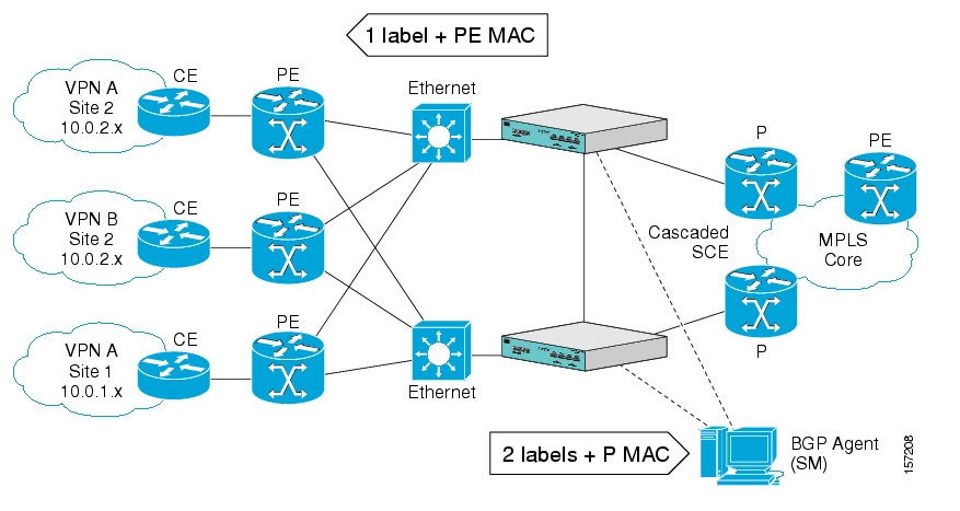
The system supports:
2015 MPLS/VPN subscribers
57,344 different labels (including upstream and downstream, and including the bypassed VPNs)
256 PEs per SCE platform
4 interfaces per PE
Mutually exclusive system modes
When the system works in MPLS/VPN mode, the following modes are not supported:
Other tunneling modes (MPLS/TE, L2TP, VLAN, etc…).
TCP Bypass-establishment
DDoS
Flow Filter TOS rules – When the MPLS/VPN feature is activated, the flow filter mode is automatically switched to tunnel-id. When the feature is de-activated, the flow filter mode remains tunnel-id.
This provides easy configuration of MPLS/VPN. To assure correct and consistent configuration of the TOS/Tunnel-ID mode, the system does not allow configuration of TOS based rules when in tunnel-ID and vice versa
Number of MPLS labels
The choice of the unique VPN site must be based on the BGP label only. The BGP label must be the innermost label.
The MPLS/VPN solution supports various combinations of labels. See Additional MPLS Pattern Support .
The system does not support VPNs for which other MPLS-related features, such as MPLS-TE or MPLS-FRR, are enabled.
Subscriber-related limitations
The following subscriber-related limitations exist in the current solution:
The SM must be configured to operate in PUSH mode.
VLAN subscribers cannot be used.
Two sites of the same VPN must be aggregated into one subscriber if the following conditions are both true:
They are both connected to the same SCE platform
They both communicate with a common remote site using the same upstream labels and P router.
TCP related Requirements
Number of Upstream TCP Flows – There must be enough TCP flows opening from the subscriber side on each PE-PE route in each period of time. The higher the rate of TCP flows from the subscriber side, the higher the accuracy of the mechanism can be.
This chapter explains how to configure MPLS/VPN support. Both the SCE platform and the SM must be properly configured.
There are three main steps to configure the SCE platform for MPLS/VPN support:
Correctly configure the MPLS tunneling environment, disabling all other tunneling protocols, as well as disabling VLAN support.
Configure the MAC resolver.
Define all PE routers, specifying the relevant interface IP addresses necessary for MAC resolution.
In order for MPLS/VPN support to function, the environment must be configured correctly, specifically the following are required:
All other tunneling protocols must be configured to the default mode.
VLAN support must be configured to the default mode.
Check the running configuration to verify no user-configured values appear for tunneling protocols or VLAN support, indicating that they are all in default mode.
Use the following command to check the current running configuration for configuration of the tunneling/VLAN environment:
From the
SCE#prompt, typeshow running-configand press Enter.
If VLAN or tunneling support is in default mode, skip the relevant step in the following procedure.
To configure the MPLS environment, complete the following steps:
Configure VLAN support to default mode:
From the
SCE(config if)#prompt, typedefault vlanand press Enter.Disable all other tunneling protocol support:
From the
SCE(config if)#prompt, typeno IP-tunneland press Enter.Enable the MPLS auto-learning mechanism.
From the
SCE(config if)#prompt, typeMPLS VPN auto-learnand press Enter.
Note
All subscribers with tunnel mappings must be cleared in order to change the tunneling mode. If the connection with the SM is down, use the no subscriber all with-tunnel-mappings CLI command (see Removing Subscribers with Tunnel Mappings).
Each PE router that has managed MPLS/VPN subscribers behind it must be defined using the following CLI command.
The following options are available:
PE-ID — IP address that identifies the PE router.
Interface-IP — Interface IP address for the PE router. This is used for MAC resolution.
At least one interface IP address must be defined per PE router.
Multiple interface IP addresses may be defined for one PE router.
In the case where the PE router has multiple IP interfaces sharing the same MAC address, it is sufficient to configure just one of the PE interfaces
vlan — A VLAN tag can optionally be provided for each interface IP.
Two interfaces cannot be defined with the same IP address, even if they have different VLAN tags. If such a configuration is attempted, it will simply update the VLAN tag information for the existing PE interface.
To define the PE routers in the system, use the following command for each PE router:
From the
SCE(config if)#prompt, typeMPLS VPN PE-ID<IP> Interface-IP <IP> [vlan <vlan>][Interface-IP <IP> [vlan <vlan>]]and press Enter.
To remove a specified interface from a PE router, use the following command:
From the
SCE(config if)#prompt, typeno MPLS VPN PE-ID<IP>Interface-IP<IP>and press Enter.
Use these commands to remove one or all defined PE routers.
Please note the following:
You cannot remove a PE if it retains any MPLS mappings. You must logout the VPN before removing the router it uses.
Removing the last interface of a PE router removes the router as well. Therefore, you must logout the relevant VPN in order to remove the last interface.
Likewise, all MPLS VPNs must be logged out before using the
no PE-Databasecommand below, since it removes all PE routers.
The MAC resolver allows the SCOS to find the MAC address associated with a specific IP address. The MAC resolver must be configured when the SCE platform operates in MPLS/VPN mode, in order to translate the IP addresses of the provider edge router interfaces to their respective MAC addresses.
The MPLS/VPN mode needs the MAC resolver, as opposed to the standard ARP protocol, because ARP is used by the management interface, while MPLS/VPN uses the traffic interfaces of the SCE platform, which ARP does not include.
The MAC resolver database holds the IP addresses registered by the clients to be resolved. The IP addresses of the routers are added to and removed from the database in either of two modes:
Dynamic mode (default)
In this mode, the system listens to ARP messages of the configured PE interfaces, and this way it stays updated with their MAC addresses. There is no configuration required when operating in dynamic mode.
Benefit: it works even if the MAC address of the PE interface changes.
Drawback: depending on the specific network topology, the MAC resolution convergence time may be undesirably long.
Static mode
In this mode, the MAC address of each PE router must be explicitly defined by the user.
Benefit: no initial delay until IP addresses converge
Drawback: PE interface is not automatically updated via ARP updates; therefore it doesn't automatically support cases where the MAC address changes on the fly.
However, for statically configured MAC addresses, a user log message appears when the system detects that the MAC address changed. This can be used by the operator to configure the new address.
These two modes can function simultaneously; therefore selected PE routers can be configured statically, while the rest are resolved dynamically
For more information regarding the MAC resolver, refer to the Cisco Service Control Engine Software Configuration Guide.
Use this command to add a static IP entry for a PE router to the database.
The following options are available:
ip address — The IP address entry to be added to the database.
vlan tag — VLAN tag that identifies the VLAN that carries this IP address (if applicable).
mac address — MAC address assigned to the IP address, in xxxx.xxxx.xxxx format.
Use this command to remove a static IP entry for a PE router from the database.
The following options are available:
ip address — The IP address entry to be removed from the database.
vlan tag — VLAN tag that identifies the VLAN that carries this IP address (if applicable).
mac address — MAC address assigned to the IP address, in xxxx.xxxx.xxxx format.
There are two main steps to configure the SM for MPLS/VPN support:
Edit the p3sm.cfg configuration file to specify the field in the BGP messages that should be used by the SM for MPLS-VPN identification.
Install and configure the BGP LEG (refer to the SCM SM MPLS/VPN BGP LEG Reference Guide).
The SM configuration file, p3sm.cfg must be configured to specify the field in the BGP messages that should be used by the SM for MPLS-VPN identification.
To configure the SM for MPLS/VPN support, complete the following step:
Add the following section to the p3sm.cfg configuration file:
# The following parameter enables SM operation with MPLS-VPN support.
[MPLS-VPN] # The following parameter determines field in the BGP messages that should be used
# for MPLS-VPN identification, in correlation to the MPLS-VPN mappings that were
# previously set to the SM.
# possible values: "rd" or "rt".
# (default: rt)
vpn_id=rt
An optional parameter may be turned on to facilitate troubleshooting the BGP LEG installation. This parameter turns on detailed logging of messages received from the BGP LEG. It should only be turned on when necessary for troubleshooting and should always be turned off for normal operation of the system.
To configure the SM for troubleshooting MPLS/VPN support, complete the following step:
Add the following section to the p3sm.cfg configuration file:
# The following parameter turns on detailed logging of messages received from the BGP LEG
# should be changed to true only during troubleshooting
# (default: false)
log_all=true
This chapter explains how to manage MPLS/VPN support.
The SCE platform CLI allows you to do the following:
Display subscriber mappings
Monitor subscriber counters
Monitor PE routers
Monitor bypassed VPNs
Use the following Viewer commands to display subscriber mappings. These commands display the following information:
All the MPLS/VPN mappings for a specified subscriber
The number of MPLS/VPN mappings for a specified subscriber
The subscriber to whom a specified downstream mapping (PE loopback IP address & BGP label) is mapped
To display all the MPLS/VPN mappings for a specified subscriber, use the following command:
From the
SCE#prompt, typeshow interface LineCard 0 subscriber name<name> mappingsand press Enter.
Sample output:
Subscriber 'SubscriberX_1122334455' mappings:
Downstream MPLS Mappings:
PE-ID = 1.1.1.1 Mpls Label = 30
PE-ID = 1.1.1.1 Mpls Label = 256
PE-ID = 1.1.1.1 Mpls Label = 2
PE-ID = 1.1.1.1 Mpls Label = 3
PE-ID = 1.1.1.1 Mpls Label = 4

=====> Total Downstream Mappings: 5
Upstream MPLS Mappings:
Upstream MPLS label: (MAC = 00:50:04:b9:c8:a0 BGP label = 0x14, LDP Label = 0xa)

=====> Total Upstream Mappings: 1
The keyword "mappings" limits the output to the MPLS/VPN mapping information only. If the keyword is not used, all subscriber information is displayed, including the mappings.
To display only the number of MPLS/VPN mappings for a specified subscriber, use the following command:
From the
SCE#prompt, typeshow interface LineCard 0 subscriber name<name> mappings | include Totaland press Enter.
Sample output:
=====> Total Downstream Mappings: 5 =====> Total Upstream Mappings: 1
Use this command to remove all learned upstream labels of a specified VPN subscriber.
This command, in effect, causes early label aging. Clearing the mappings allows relearning; labels will probably be quickly relearned after they have been cleared. Therefore, this command is useful when you want to update the mappings without waiting for the standard aging period.
From the
SCE(config if)#prompt, typeno subscriber name<name> mapping upstream mpls alland press Enter.
Use the following Viewer command to display subscriber counters, including those related to MPLS/VPN mappings.
When MPLS/VPN subscribers are enabled, the following related counters appear in addition to the basic subscriber counters:
MPLS/VPN subscribers:
Current number of MPLS/VPN subscribers
Maximum number of MPLS/VPN subscribers
MPLS/VPN subscribers are also counted in the general subscribers counters, but the general subscribers maximum number does not apply to MPLS/VPN subscribers, which have a smaller maximum number.
MPLS/VPN mappings:
Current number of used MPLS/VPN mappings
Maximum number of MPLS/VPN mappings
Note that these values reflect the total number of mappings, not just the mappings used by MPLS/VPN subscribers. Bypassed VPNs also consume MPLS/VPN mappings.
From the
SCE#prompt, typeshow interface LineCard 0 subscriber db countersand press Enter.
Sample Output:
Current values:
===============
Subscribers: 2 used out of 99999 max.
Introduced subscribers: 2.
Anonymous subscribers: 0.
Subscribers with mappings: 2 used out of 99999 max.
IP mappings: 0 used.
MPLS/VPN subscribers are enabled.
MPLS/VPN mappings: 2 used out of 57344 max.
MPLS/VPN subscribers: 2 used out of 2015 max.
Subscribers with open sessions: 0.
Subscribers with TIR mappings: 0.
Sessions mapped to the default subscriber: 0.
Peak values:
============
Peak number of subscribers with mappings: 2
Peak number occurred at: 14:56:55 ISR MON November 7 2005
Peak number cleared at: 13:29:39 ISR MON November 7 2005
Event counters:
===============
Subscriber introduced: 2.
Subscriber pulled: 0.
Subscriber aged: 0.
Pull-request notifications sent: 0.
State notifications sent: 0.
Logout notifications sent: 0.
Subscriber mapping TIR contradictions: 0.
Note
The maximum number of subscribers when MPLS/VPN support is enabled is actually the maximum noted in the MPLS/VPN subscribers line (2015), rather than the maximum noted in the first line.
Use the following Viewer command to display MPLS/VPN information.
From the
SCE#prompt, typeshow interface LineCard 0 mpls vpnand press Enter.
Sample Output:
MPLS/VPN auto-learn mode is enabled.
MPLS/VPN subscribers: 0 used out of 2015 max
Total HW MPLS/VPN mappings utilization: 0 used out of 57344 max
MPLS/VPN mappings are divided as follows:
downstream VPN subscriber mappings: 0
upstream VPN subscriber mappings: 0
non-vpn upstream mappings: 0
downstream bypassed VPN mappings: 0
upstream bypassed VPN mappings: 0
Use the following Viewer commands to monitor PE routers. These commands provide the following information:
Configuration of all currently defined PE routers.
Configuration of a specified PE router.
The SM CLU allows you to do the following:
Add, remove, and display MPLS/VPN mappings for a specified subscriber (VPN)
Clear all MPLS/VPN mappings from the SM database
Use the p3subs utility to manage subscriber MPLS/VPN mappings.
The following options are available:
Subscriber-Name — The name assigned to the VPN when it was added as a subscriber.
RT@PE-IP — The mapping to be assigned to the subscriber/VPN. Multiple mappings can be specified using a comma.
RT = the route target of the VPN, specified using the ASN:n notation or the IP:n notation
Note that the Route Distinguisher may be specified rather than the route target
PE-IP = the loopback IP of the PE router connected to that VPN
To manage individual subscriber MPLS/VPN mappings, use the following command:
From the shell prompt, type a command having the following general format:
p3subs<operation> --subscriber=<Subscriber-Name> --mpls-vpn=<RT@PE-IP>[--additive-mapping]
The following table presents all the p3subs operations relevant to managing mappings.
Table 13.2. p3subs Mapping Operations
|
Operation |
Description |
|---|---|
|
--set |
Add/update a subscriber. If the mapping exists, replaces the existing mapping, unless the additive-mapping option is used. |
|
--remove-all-mappings |
Removes all the mappings of specified subscriber. |
|
--remove-mappings |
Removes specified mapping of specified subscriber. |
Table 13.3. p3subs Mapping Options
|
Operation |
Description |
|---|---|
|
--additive-mapping |
Adds the specified mappings to the existing ones (instead of replacing the existing mappings when this option is not used). Used with the set operation. |
SNMP support for MPLS/VPN auto-learn is provided in two ways:
MIB variables
SNMP traps
The mplsVpnAutoLearnGrp MIB object group (pcubeSEObjs 17) contains information regarding MPLS/VPN auto-learning.
The objects in the mplsVpnAutoLearnGrp provide the following information:
maximum number of mappings allowed
current number of mappings
For more information, see the "Proprietary MIB Reference" in the Cisco Service Control Engine Software Configuration Guide.
There is one MPLS/VPN-related trap:
mplsVpnTotalHWMappingsThresholdExceeded (pcubeSeEvents 45)
In order to provide online notification of a resource deficiency, when the system reaches a level of 80% utilization of the hardware MPLS/VPN mappings, a warning message appears in the user log, and this SNMP trap is sent.
Both the warning and the trap are sent for each 100 mappings that are added after the threshold has been exceeded.
The Service Control Management Protocol (SCMP) is a protocol that integrates the SCE platform and the ISG (Intelligent Service Gateway) functionality of the Cisco routers, thereby providing a mechanism that allows the ISG and the SCE platform to manage subscriber sessions together without requiring coordination and orchestration by additional components.
The SCMP is a Cisco proprietary protocol that uses the RADIUS protocol with CoA (Change of Authorization) support as a transport layer. The SCMP provides connection management messages, subscriber management and subscriber accounting messages.
Each subscriber in the SCE platform represents a session in the SCMP peer (as defined by the ISG terminology).
Connection management
The SCE platform initiates the connection to the peer device. On SCMP connection establishment, the SCE platform and ISG negotiate the following details:
Introduction mode – whether the SCMP peer must send a session-provisioning message on session creation.
Keep-alive message interval
Protocol version
Subscriber Management
The SCMP peers can work in either of two introduction modes. These introduction modes affect only how and when a session is created on the SCE platform:
The SCMP peer provisions the session to the SCE platform when it is created in the peer device (push)
The SCE platform queries the SCMP peer regarding unmapped IP traffic (pull).
The SCMP uses queries as a backup to the push introduction mode, in order to be robust to issues such as networking problems and SCE platform reboot.
In addition to session creation, the SCMP supports the following operations:
Change of session policy and network IDs using the update-session message
Removal of the session when the user logs-out
Activate-policy, which changes the session policy
Deactivate-policy, which sets the policy value of the related anonymous-group template (based on the session manager)
Subscriber Accounting
On session creation, the SCE platform sends an accounting start message for the session and on logout, it sends an accounting stop message for the session. In addition, for each SCA BB service-counter an accounting-session is maintained (start, interim and stop messages), which provides information regarding the relevant volume, flow-count and duration.
The accounting messages are based on the new Subscriber-Acounting RDR and are sent according to the interval defined in the PQB configuration.
SCMP terminology is similar to, but not identical to, existing SCE platform terminology. It is derived from the ISG terminology, since every SCE subscriber is actually an ISG session.
Subscriber – The client who is purchasing service from the Service Provider and is receiving the bill.
User – A member, employee or guest at the subscriber household or business using the service.
Session – A logically identifiable entity on the service gateway that represents communication with a peer. It is based on a unique combination of one or more Identity Keys such as an IP address, a subnet, a MAC address, a tunnel termination interface (PPP) or a port.
Each session is assigned a unique identifier.
Flow – Characterized by a number of parameters identifiable from the traffic such as source IP address, destination IP address, source port, destination port, protocol and in some cases direction.
SCMP Peer – A Cisco device running IOS with the ISG module enabled.
Identity Key – One of the keys that help identify a Session. The identity keys that are relevant to the SCE-ISG control-bus are:
IP Address/Subnet
IP Subnet
Policy – Defines all aspects of subscriber session processing. A policy consists of conditions and actions. Traffic conditions will classify traffic and allow policing actions to be applied to the traffic. Policies may be provisioned, updated and removed. Policies may also be activated for a session or deactivated for a session. A policy may be referred to by name.
The following sections illustrate the basic types of SCMP deployment scenarios.
1xISG – 1xSCE
1xISG – 2xSCE (SCE cascade)
NxISG – 2xSCE (SCE cascade)
NxISG – MxSCE Via Load Balancing (MGSCP)
The following diagram illustrates a deployment using one ISG router with a single SCE platform.
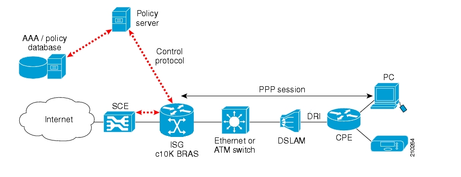
Note the following:
The red dotted lines depict the control path communication.
A deployment of this type might be used with ISG running on a service gateway or BRAS terminating a large number of subscribers. However, note that deploying only one SCE platform results in a single point of failure, which is not generally acceptable in an actual deployment.
The following diagram illustrates a deployment using one ISG router with two cascaded SCE platforms.
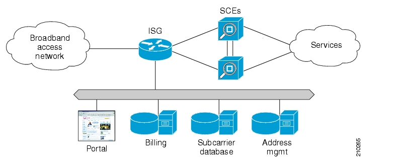
This scenario is similar to the previous one, with ISG running on a service gateway or BRAS terminating a large number of subscribers, however a second SCE platform has been added to provide redundancy. This redundancy scheme assumes that SCE platforms are connected in a cascade, with one active SCE platform and one backup.
Please note the following:
When cascaded SCE platforms are connected to one or more ISG devices, only the active SCE platform maintains a connection to the ISG devices.
You can configure the cascaded SCE platforms to receive session info from the SCMP peer on session creation or pull the session info when the subscribers traffic traverses the SCE platform.
An ISG device cannot push sessions to two SCE platforms at the same time
The following diagram illustrates a deployment using multiple ISG routers with two cascaded SCE platforms.
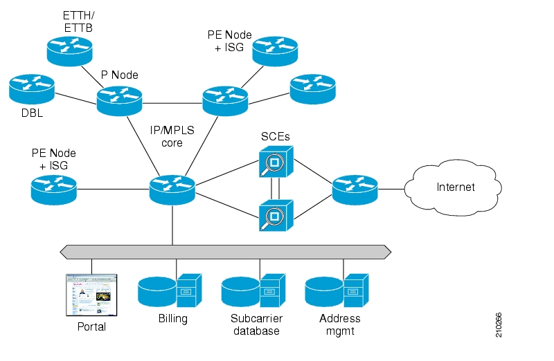
Many SPs require an edge platform with MPLS functionality to support L2 and L3 VPN services for business customers, with the possibility of running subscriber management functions for residential and business subscribers terminating on the same platform. If advanced services requiring deep packet inspection are offered, we recommend locating the SCE platforms centrally, just before traffic requiring such services exits the SP network, since not all traffic needs to be processed by SCE platforms.
Please note the following:
When cascaded SCE platforms are connected to one or more ISG devices, only the active SCE platform maintains a connection to the ISG devices.
You can configure the cascaded SCE platforms to receive session info from the SCMP peer on session creation or pull the session info when the subscribers traffic traverses the SCE platform.
An ISG device cannot push sessions to two SCE platforms at the same time
The following diagram illustrates a deployment using multiple ISG routers with multiple SCE platforms via load balancing. This is the scenario required for a MGSCP deployment.
Figure 14.4. Deployment Scenario: Multiple ISG Routers with Multiple SCE Platforms via Load Balancing
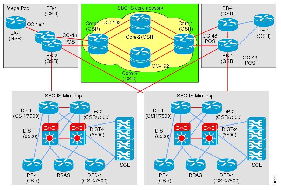
This scenario includes a number of SCE platforms connected to the 7600/6500 switch. For efficient control of subscriber flows, the same SCE platform must process both directions of each subscriber flow, since the SCE platform keeps the subscriber context. The 7600/6500 switch to which the SCE platforms are connected acts as a dispatching element, distributing subscriber flows between SCE platforms and guaranteeing that all flows of a specific subscriber will pass through the same SCE platform.
This scenario assumes that one (or sometimes more) of the devices in the cluster is redundant.
Please note the following:
An ISG device cannot push sessions to two SCE platforms at the same time
You must configure multiple SCE platforms with load-balancing (MGSCP) to work in pull integration mode.
An SCMP peer device is a Cisco device running IOS with the ISG module enabled. The SCE platform supports the ability to communicate with several SCMP peer devices at the same time. However, each peer device manages its own subscribers and the corresponding subscriber network IDs. The SCE platform recognizes which subscribers belong to which peer device. There are two mechanisms that accomplish this:
Logon operation
Each SCMP peer device is assigned a unique ID called the Manager-Id. This ID is attached to each subscriber from the moment it is created in the subscriber database, based on the SCMP peer that logged-in the subscriber.
Anonymous groups
An anonymous group is a specified IP range, possibly assigned a subscriber template (see Anonymous Groups and Subscriber Templates).
SCMP associates each SCMP peer device with at least one anonymous group. SCMP generates subscribers for this anonymous group when it detects traffic from the SCMP peer device that is not mapped to any subscriber. SCMP assigns the SCMP peer manager-Id to this generated anonymous-subscriber. If you have assigned a subscriber template to the group, the anonymous subscribers generated have properties as defined by that template. If you have not assigned a subscriber template, the default template is used.
One SCE platform supports a maximum of 20 SCMP peer devices.
The SCMP attempts to maintain an open connection to each peer device.
The following figure illustrates the SCMP connection state functionality.
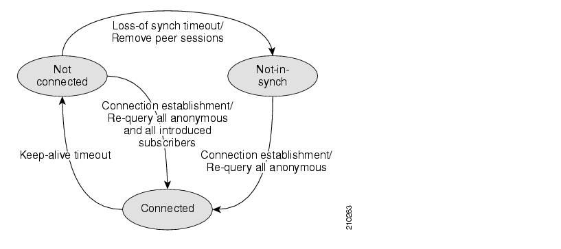
The loss-of-sync timeout prevents the SCE platform from retaining sessions that are obsolete and whose identity-keys have been replaced or moved to other sessions thus miss-classification risk is limited
Subscriber virtualization allows multiple SCMP peer devices to simultaneously manage subscribers in the SCE platform without interfering with each other. (Note that each device must handle a distinct set of subscribers and network IDs.)
The following mechanisms support subscriber virtualization:
SCMP adds the Manager-Id field to each subscriber record in the database.
All SCMP subscriber provisioning operations include the Manager-Id parameter for each subscriber.
SCMP performs synchronizations in the context of the Manager-Id
SCMP dispatches queries according to the configuration of the anonymous subscriber groups
The SCMP requires the use of a globally unique identifier (GUID) that is created by and identifies each SCMP peer device. The GUID is a 16-character-long ASCII string. The SCE platform uses the GUID for all communication with the SCMP peer.
SCMP creates the SCE subscriber ID from the concatenation of any or all of the following user-related RADIUS attributes, with the GUID as the suffix.
Calling-Station-Id
NAS-port-Id
User-Name
The user defines this subscriber ID structure via CLI.
You can configure the following options for the SCMP:
Enable the SCMP
Configure the SCMP peer device to push sessions to the SCE platform
Allow the SCMP peer device to provision each subscriber to only one SCE platform.
Define the SCMP keep-alive interval
Define the SCMP reconnect interval
Define the loss-of-sync timeout
Define the subscriber Id structure
By default, the SCMP is disabled.
When SCMP establishes a connection with an SCMP peer device, it informs the device whether the SCMP is configured to push sessions or to wait till the sessions are pulled by the SCE platform. Use this command to specify push mode. Use the no form of the command to specify pull mode.
This configuration takes effect only after the connection is re-established.
Default is disabled (pull mode).
When SCMP establishes a connection with an SCMP peer device, it informs the device whether the SCMP is configured to allow each subscriber to be provisioned to only one SCE platform.
Use this command to configure the SCMP peer device to verify that each subscriber is provisioned to only one SCE platform. If a subscriber was provisioned to a different SCE platform, the SCMP removes it from the previous SCE platform and provisions it to the new SCE platform. This configuration is required in MGSCP topology where, in the event of a fail-over between SCE platforms, subscribers might move from one SCE platform to another. If transferred subscribers are not cleared from the previous SCE platform, it can cause capacity issues.
Use the no form of the command to allow SCMP to provision subscribers to more than one SCE platform .
This configuration takes effect only after the connection is re-established.
Default is disabled (subscribers can be provisioned to more than one SCE platform).
The keep-alive interval is the amount of time between keep-alive messages to the SCMP peer device. If the SCMP does not receive a response from the SCMP peer device within the defined interval, the connection is assumed to be down; and the SCMP changes the connection state to false and begins attempts to reconnect.
The following options are available:
interval — Interval between keep-alive messages from the SCE platform to the SCMP peer device in seconds
Default = 5 seconds
The reconnect interval is the amount of time between attempts by the SCE platform to reconnect with an SCMP peer. The SCE platform attempts to reconnect to the SCMP peer device at the defined intervals by sending an establish-peering-request message.
The following options are available:
interval — Interval between attempts by the SCE platform to reconnect with an SCMP peer, in seconds
Default = 30 seconds
The loss of sync timeout interval is the amount of time between loss of connection between the SCE platform and an SCMP peer device and the loss-of-sync event. (In order to prevent miss-classification, loss-of-sync event removes all subscribers that were provisioned by the relevant SCMP peer device.)
The following options are available:
interval — Loss of sync timeout interval in seconds
Default = 90 seconds
Adding an SCMP peer device is a two-step process:
Define the device, configuring the following parameters:
device name
RADIUS host
RADIUS shared secret
authorization port number (optional)
accounting port number (optional)
Associate the device with one or more unmapped anonymous groups.
The following options are available:
peer_device_name — User-assigned name of the SCMP peer device
radius_hostname — IP address or host-name of the RADIUS host (if a host-name is used, it must be valid at time of the configuration)
shared_secret — RADIUS shared secret
auth-port# (optional) — authorization port number
acct-port# (optional) — accounting port number
Defaults:
auth-port# — 1812
acct-port# — 1813
This command defines the specified anonymous group to be the IP range of the SCMP peer device. You must define the specified SCMP peer device before assigning the anonymous group.
The following options are available:
group-name — Name of the anonymous subscriber group to be associated with the specified SCMP peer device.
range (optional) — IP range defined for the anonymous group
template (optional) — group template assigned to the anonymous group
peer-device-name — User-assigned name of the SCMP peer device
Use this command to clear all the subscribers that are managed by a specified SCMP peer device.
The following option is available:
peer-device-name — User-assigned name of the SCMP peer device
You cannot delete an SCMP peer device that has anonymous groups assigned to it. You must remove all associated anonymous groups before deleting the device.
To delete an SCMP peer device, complete the following steps:
First remove all anonymous groups assigned to the device:
From the
SCE(config if)#prompt, typeno subscriber anonymous-group name<group-name>[IP-range<range>][template<template>] scmp name<peer-device-name>and press Enter.Repeat this step for all anonymous groups assigned to the SCMP peer device.
When all anonymous groups have been removed from the device, exit LineCard Interface Configuration mode:
From the
SCE(config)#prompt, typeexit.Delete the device:
From the
SCE(config)#prompt, typeno scmp name<peer_device_name>and press Enter.
You can define the structure of the subscriber ID via this command by specifying which of the following elements to include and in which order:
Calling-Station-Id
NAS-port-Id
User-Name
The GUID is always appended at the end of the subscriber ID as defined by this command.
The following options are available:
1st element — any one of the following:
Calling-Station-Id
NAS-Port-Id
User-Name
2nd element (optional) — any one of the following (if specified, usually not the option specified as the first element):
Calling-Station-Id
NAS-Port-Id
User-Name
3rd element (optional) — any one of the following (if specified, usually the remaining option not specified as either of the first two elements):
Calling-Station-Id
NAS-Port-Id
User-Name
Default = no elements concatenated with the GUID
You must disable the SCMP interface before executing this command.
To define the structure of the subscriber ID, complete the following steps:
Disable the SCMP:
From the
SCE(config)#prompt, typeno scmpand press Enter.Define the subscriber ID:
From the
SCE(config)#prompt, typescmp subscriber id append-to-guid radius-attributes Calling-Station-Id | NAS-Port-Id | User-Name [Calling-Station-Id | NAS-Port-Id | User-Name] [Calling-Station-Id | NAS-Port-Id | User-Name]and press Enter.Enable the SCMP:
From the
SCE(config)#prompt, typescmpand press Enter.
You can configure the following options for the RADIUS client
Define the parameters for retransmitting unacknowledged messages.
The RADIUS client polls the sockets to receive the next message and calls the SCMP engine to handle it, based on the type of the received message. Messages that were not acknowledged can be retransmitted up to the configured maximum number of retries.
The following options are available:
times — The maximum number of times the RADIUS client can try unsuccessfully to send a message.
Default = 3
timeout (optional) — Timeout interval for retransmitting a message, in seconds
Default = 1 second
You can monitor the following components of the SCMP environment:
SCMP
RADIUS client
Use the following commands to monitor the SCMP.
These commands provide the following information:
General SCMP configuration
Configuration of all currently defined SCMP peer devices.
Configuration of a specified SCMP peer device.
Statistics for either all SCMP peer devices or a specified SCMP peer device.
The following option is available:
device-name — The name of the specific SCMP peer device for which to display the configuration or statistics.
To display the general SCMP configuration, use the following command:
From the
SCE#prompt, typeshow scmpand press Enter.Sample Output
SCMP enabled: yes
Keep-alive interval: 5 seconds
Loss of synchronization timeout: 90 seconds from disconnection
Reconnection interval: 30 seconds
Force subscriber on a single SCE: no
Peer sends subscriber data on session start
Subscriber Id structure: GUID
To display the configuration of all currently defined SCMP peer devices, use the following command:
From the
SCE#prompt, typeshow scmp alland press Enter.
To display the configuration of a specified SCMP peer device, use the following command:
From the
SCE#prompt, typeshow scmp name<device-name>Sample Output
SCMP Connection 'isg' status:
10.56.208.91 auth-port 1812 acct-port 1813
Connection state: Connected
Peer protocol-version: 1.0
Keep-alive interval: 5 seconds
Force single SCE: No
Send session start: Yes
Time connected: 9 seconds
To display the statistics for all SCMP peer devices, use the following command:
From the
SCE#prompt, typeshow scmp all countersand press Enter.
To display the statistics for a specified SCMP peer device, use the following command:
From the
SCE#prompt, typeshow scmp name<device-name>countersand press Enter.Sample Output
SCMP Connection 'isg' counters:
Total messages sent: 72
Total messages received: 72
Establish requests sent: 1
Establish replies received: 1
Accounting requests sent: 20
Accounting replies received: 20
Subscriber queries sent: 0
Subscriber query response recv: 0
Request retry exceeded: 0
Requests replied with errors: 0
Subscriber requests received: 50
Subscriber responses sent: 50
Failed Requests: 0
Keep-alive sent: 1
Keep-alive received: 1
Use the following command to monitor the SCMP RADIUS client. This command displays the general configuration of the RADIUS client.
This section explains how to monitor SCE platforms that are installed in real traffic.
As with any network device, the SCE platform has its performance and capacity envelopes. As the network evolves, the utilization of the SCE platform can increase and these envelopes might be reached. It is, therefore, advisable to monitor SCE platform to be sure that utilization remains at a level that supports reliable and consistent service.
When the SCE platform reaches its performance envelopes, it activates certain mechanisms that insure that no traffic will be dropped while in this state. These mechanisms will prioritize packet handling over service related actions. As a result, symptoms of service loss might be experienced. Following are several examples:
Broken reports during the congestion period (sometimes appears as saw-tooth pattern).
Bandwidth enforcement levels are not met.
No UDP traffic is being reported (this is because the SCE platform will automatically filter all UDP traffic in certain cases as a last resort).
Monitoring the SCE platform can be divided onto two main areas:
Monitoring SCE platform utilization
Monitoring service loss
The SCE platform exposes several indicators in order to allow the network operators to easily monitor whether it is working within its performance and capacity specifications:
CPU Utilization
Flows capacity
Subscribers capacity
SNMP
tpCpuUtilization, available for each Traffic Processor (TpInfoEntry) in the PCubeSeMib.mib.
CLI command
show snmp MIB pcube-SE-MIB traffic-processor | include tpCpuUtilization
It is advisable to consider sizing of the solution when the CPU utilization exceeds 75% regularly at peak hours.
SNMP
tpFlowsCapacityUtilization, available for each Traffic Processor (TpInfoEntry) in the PCubeSeMib.mib
CLI command
show snmp MIB pcube-SE-MIB traffic-processor | include tpFlowsCapacityUtilization
It is advisable to consider sizing of the solution when the flows capacity utilization exceeds 90% regularly at peak hours.
SNMP
subscribersInfoEntry, available in the PCubeSeMib.mib
CLI command
show snmp MIB pcube-SE-MIB subscriber
The SCE 2000 platform supports up to 80K subscribers, while the SCE 1000 supports up to 40K subscribers. You should make sure that the number of Introduced Subscribers plus the number of Anonymous Subscribers stays below this figure.
It is advisable that when subscribers utilization exceeds 90%, special attention should be given and sizing should be reconsidered.
Service Loss is an event which occurs when the SCE platform does not provide the processing it was expected to perform for any transaction in the network. This can occur due to either CPU or Flows shortage.
There are two different situations which can result with service loss in the SCE platform:
Temporary – This might occur when some network pattern which is short in its nature occurred and caused the SCE platform to exhaust some of it resources temporarily.
An example could be a DDoS attack that the SCE platform could not detect and filter.
This is usually measured in seconds.
Permanent – In cases where the SCE platform is installed in locations where the network traffic does not match its capacity and performance envelopes, permanent service loss can occur.
This is measured in hours.
Service loss is defined as the ratio of the number of packets that did not receive service as expected to the total number of packets that were processed by the SCE platform.
SNMP
tpServiceLoss MIB available for each traffic processor (TpInfoEntry)
It is expected that the SCE platform user will define timeslots in which this variable is monitored (reset it between timeslots).
Note that the units for this variable are 0.001% and the information is rounded down.
This appendix describes the pcube proprietary MIB supported by the SCE platform. A MIB (Management Information Base) is a database of objects that can be monitored by a network management system (NMS). The SCE platform supports both the standard MIB-II and a proprietary Service Control Enterprise MIB. This proprietary pcube MIB enables the external management system to perform configuration, performance, troubleshooting and alerting operations specific to the SCE platform, and therefore not provided by the standard MIB.
Note
Information and proprietary MIB files supported by the SCOS can be downloaded from: http://www.cisco.com/public/sw-center/netmgmt/cmtk/mibs.shtml under the Cisco Service Routing Products section.
The pcube Enterprise MIB splits into into four main groups:
Products
Modules
Management
Workgroup
The pcube enterprise tree structure is defined in a MIB file named PCUBE-SMI.my.
Note
The following object identifier represents the pcube Enterprise MIB:
1.3.6.1.4.1.5655, or iso.org.dod.internet.private.enterprise.pcube.
The figure below illustrates the pcube Service Control Enterprise MIB structure.
Conventions used in the diagram:
Dotted arrows surrounding a unit or units indicate that the component is described in the MIB file specified below the line.
A shadowed box indicates that the component is described in its own MIB file.
The pcubeProducts subtree
The pcubeProducts subtree contains the OIDs of Cisco Service Control products. These OIDs are used only to describe the Cisco Service Control platforms, not as roots for other OIDs.
This subtree does not contain online data, just global definitions.
The pcubeProductsMIB is defined the following MIB file :
PCUBE-PRODUCTS-MIB.my
The pcubeModules subtree
The pcubeModules subtree provides a root object identifier under which MIB modules can be defined.
This subtree does not contain online data, just global definitions.
The pcubeMgmt subtree
The pcubeMgmt subtree is the root for pcube MIBs that are relevant to multiple products.
The pcubeWorkgroups subtree
The pcubeWorkgroups subtree contains the actual MIBs for Cisco Service Control devices and sub-devices. This is where the SCE platform, the dispatcher, and also the SCA BB application, hook their actual OIDs and notifications. This means that the branches in this subtree are defined in multiple MIB files.
The pcubeConfigCopyMib subtree
The pcubeConfigCopy MIB is a subset of the Cisco Config-Copy-MIB ported to the pcube enterprise subtree. It supports only local copying of running config to startup config.
The pcubeConfigCopyMIB is defined the following MIB file :
PCUBE-CONFIG-COPY-MIB.my
The config copy MIB is intended for use by all pcube products, and is therefore placed under the pcubeMgmt subtree.
The pcubeSE MIB
The pcubeSE MIB comprises two branches:
pcubeSeEvents: Contains the OIDs used for sending enterprise-specific notifications.
pcubeSEObjs : Contains the OIDs that belong to the SCE platform, divided into groups according to functionality.
The pcubeSeMIB described above contains information about the SCE platform. Information regarding the SML application running on the SCE platform is available through the following two interfaces:
application and subscriber groups of the pcubeSeMIB
pcubeEngageMIB
These groups allow the operator to view information exposed by the application. In essence, these groups contain tables that allow access to viewables and tuneables defined in the installed SML application. This mechanism is general, and does not require specific adjustments of the SCOS platform for an application. Any installed application can define variables that would then automatically be accessible through the application or subscriber groups.
The application group contains information about the application itself. It also contains two tables:
appPropertiesTable:
Contains a list of properties of the application. These properties are SML viewables and tuneables that are defined in global scope. Each property has a name and a type (both are strings).
This table is updated when the application is installed, and has read-only access. It is therefore managed by the agent (the SCOS).
appPropertiesValueTable:
Contains information about the application properties that appear in the appPropertiesTable, described above. For each such property, a value is available in one or more formats, as appropriate:
String
Integer
64-bit Integer.
This table is a read-write table, which uses the row-status mechanism. With this mechanism it is possible for a management station to add rows to an SNMP table in an pseudo-atomic way. The RowStatus type is defined in SNMPv2-SMI.
This table is cleared when an application is unloaded, or when the system resets. The manager may add rows to the table after the system starts, with properties taken from the appPropertiesTable, and then it is possible to poll these variables for their values. It is the manager’s responsibility to read the value in the correct format (according to the “type” field in the appPropertiesTable).
Note that the values cannot be changed through SNMP. Tuneables and Viewables are the same in this respect, they can only be viewed.
Note as well that all the properties in the application group are global properties.
The subscribers group contains global statistics about the subscribers. It also contains two tables, which work in a mechanism very similar to that of the application properties tables described above:
subscribersPropertiesTable:
Contains a list of “subscriber properties” that the installed application has defined. These properties are SML viewables and tuneables that are defined in subscriber scope. Each property has a name and a type (both are strings).
This table is updated when the application is installed, and has read-only access. It is therefore it is managed by the agent (the SCOS).
subscribersPropertiesValueTable:
Like the appPropertiesValueTable, this table also uses the RowStatus mechanism to allow addition and removal of rows by the manager. Once a row is created in the subscriberValueTable, it is possible to poll the value of the property for the requested subscriber. The values are given in three formats (string, integer, and 64-bit integer, it being the responsibility of the manager to read the appropriate field, according to the type of the property)
In order to retrieve the value of a subscriber property, the manager must supply the following:
The name of the property (taken from the subscriberPropertyTable)
The name of the subscriber for which this value should be polled (the name of the subscriber should be known to the manager, it is not available through SNMP).
Note that the values of the properties are read-only for viewables and tuneables alike.
This table is also used by the pcubeEngageMIB.
The application group of the pcubeSeMIB allows the manager to retrieve information about the application. However, due to its generality, it requires quite a bit of intelligence from the management station. The pcubeEngageMIB is an application-specific MIB that supplies information relevant only to the SCA BB (Engage) application.
All information that the application may want to publish is stored in viewables and tuneables. However, there is currently no automatic way for the application to declare that a certain OID should reflect a certain application variable. For this reason, the Engage application MIB is actually implemented by the SCOS.
The Engage subscriber tables rely on the SCOS subscriber value tables described above. Since there is no table that contains a list of the subscribers in the system, the only subscribers referred to in the Engage tables are the ones that appear in the SCOS subscribersPropertiesValueTable. The spvIndex is used to index the subscribers in the pcubeEngageMIB as well.
This reference describes all existing MIB objects. For each object, the following information is presented:
IDENTIFIERS MIB descriptor name and OID
DESCRIPTION Description of the object, including format and legal values, if applicable.
ACCESS Access control associated with the object:
Read only (RO)
Read/Write (RW)
SYNTAX The general format of the object.
pcubeModules provides a root object identifier from which module identity values may be assigned.
Modules:
PCUBE-SE-MIB: pcubeSeMIB (1.3.6.1.4.1.5655.2.3)
CISCO-SCAS-BB-MIB: pcubeEngageMIB (1.3.6.1.4.1.5655.2.4) (See the "SCA BB Proprietary MIB Reference" chapter in the Cisco SCA BB Reference Guide for a description of the CISCO-SCAS-BB-MIB.)
Main SNMP MIB for the Cisco SCE products such as SCE 2000 and SCE 1000. This MIB provides configuration and runtime status for chassis, control modules, and line modules on the SCOS systems.
Following is a list of the pcubeSeMIB object groups. Each object group consists of a number of related objects. All individual objects are listed and described in the pcubeWorkgroup section.
|
|
|
|
|
|
|
|
|
|
|
|
|
|
|
|
|
|
|
|
|
|
|
|
|
|
|
|
|
|
|
|
|
|
|
|
|
|
|
|
|
|
|
|
|
|
|
|
|
|
|
|
|
|
The System group provides data on the system-wide functionality of the SCE platform.
Objects:
1: sysOperationalStatus (1.3.6.1.4.1.5655.4.1.1.1)
The Chassis group defines and identifies the chassis, as well as environmental alarms related to the chassis.
Objects:
1: pchassisSysType (1.3.6.1.4.1.5655.4.1.2.1)
2: pchassisPowerSupplyAlarm (1.3.6.1.4.1.5655.4.1.2.2)
3: pchassisFansAlarm (1.3.6.1.4.1.5655.4.1.2.3)
4: pchassisTempAlarm (1.3.6.1.4.1.5655.4.1.2.4)
5: pchassisVoltageAlarm (1.3.6.1.4.1.5655.4.1.2.5)
6: pchassisNumSlots (1.3.6.1.4.1.5655.4.1.2.6)
7: pchassisSlotConfig (1.3.6.1.4.1.5655.4.1.2.7)
The Module group identifies and defines the modules, or cards, in the SCE platform.
Objects:
1: pmoduleIndex (1.3.6.1.4.1.5655.4.1.3.1.1.1)
2: pmoduleType (1.3.6.1.4.1.5655.4.1.3.1.1.2)
3: pmoduleNumTrafficProcessors (1.3.6.1.4.1.5655.4.1.3.1.1.3)
4: pmoduleSlotNum (1.3.6.1.4.1.5655.4.1.3.1.1.4)
5: pmoduleHwVersion (1.3.6.1.4.1.5655.4.1.3.1.1.5)
6: pmoduleNumPorts (1.3.6.1.4.1.5655.4.1.3.1.1.6)
7: pmoduleNumLinks (1.3.6.1.4.1.5655.4.1.3.1.1.7)
8: pmoduleConnectionMode (1.3.6.1.4.1.5655.4.1.3.1.1.8)
9: pmoduleSerialNumber (1.3.6.1.4.1.5655.4.1.3.1.1.9)
10: pmoduleUpStreamAttackFilteringTime (1.3.6.1.4.1.5655.4.1.3.1.1.10)
11: pmoduleUpStreamLastAttackFilteringTime (1.3.6.1.4.1.5655.4.1.3.1.1.11)
12: pmoduleDownStreamAttackFilteringTime (1.3.6.1.4.1.5655.4.1.3.1.1.12)
13: pmoduleDownStreamLastAttackFilteringTime (1.3.6.1.4.1.5655.4.1.3.1.1.13)
14: pmoduleAttackObjectsClearTime (1.3.6.1.4.1.5655.4.1.3.1.1.14)
The Link group defines and identifies the link. It provides information regarding the mode of operation of the link defined for each status of the platform.
Objects:
1: linkModuleIndex (1.3.6.1.4.1.5655.4.1.4.1.1.1)
2: linkIndex (1.3.6.1.4.1.5655.4.1.4.1.1.2)
3: linkAdminModeOnActive (1.3.6.1.4.1.5655.4.1.4.1.1.3)
4: linkAdminModeOnFailure (1.3.6.1.4.1.5655.4.1.4.1.1.4)
5: linkOperMode (1.3.6.1.4.1.5655.4.1.4.1.1.5)
6: linkStatusReflectionEnable (1.3.6.1.4.1.5655.4.1.4.1.1.6)
7: linkSubscriberSidePortIndex (1.3.6.1.4.1.5655.4.1.4.1.1.7)
The Disk group provides data regarding the space utilization on the disk.
Objects:
The RDR Formatter provides information regarding RDR Formatter destinations (Collection Managers), as well as RDR statistics.
Objects:
1: rdrFormatterEnable (1.3.6.1.4.1.5655.4.1.6.1)
2: rdrFormatterDestIPAddr (1.3.6.1.4.1.5655.4.1.6.2.1.1)
3: rdrFormatterDestPort (1.3.6.1.4.1.5655.4.1.6.2.1.2)
4: rdrFormatterDestPriority (1.3.6.1.4.1.5655.4.1.6.2.1.3)
5: rdrFormatterDestStatus (1.3.6.1.4.1.5655.4.1.6.2.1.4)
6: rdrFormatterDestConnectionStatus (1.3.6.1.4.1.5655.4.1.6.2.1.5)
7: rdrFormatterDestNumReportsSent (1.3.6.1.4.1.5655.4.1.6.2.1.6)
8: rdrFormatterDestNumReportsDiscarded (1.3.6.1.4.1.5655.4.1.6.2.1.7)
9: rdrFormatterDestReportRate (1.3.6.1.4.1.5655.4.1.6.2.1.8)
10: rdrFormatterDestReportRatePeak (1.3.6.1.4.1.5655.4.1.6.2.1.9)
11: rdrFormatterDestReportRatePeakTime (1.3.6.1.4.1.5655.4.1.6.2.1.10)
12: rdrFormatterNumReportsSent (1.3.6.1.4.1.5655.4.1.6.3)
13: rdrFormatterNumReportsDiscarded (1.3.6.1.4.1.5655.4.1.6.4)
14: rdrFormatterClearCountersTime (1.3.6.1.4.1.5655.4.1.6.5)
15: rdrFormatterReportRate (1.3.6.1.4.1.5655.4.1.6.6)
16: rdrFormatterReportRatePeak (1.3.6.1.4.1.5655.4.1.6.7)
17: rdrFormatterReportRatePeakTime (1.3.6.1.4.1.5655.4.1.6.8)
18: rdrFormatterProtocol (1.3.6.1.4.1.5655.4.1.6.9)
19: rdrFormatterForwardingMode (1.3.6.1.4.1.5655.4.1.6.10)
20: rdrFormatterCategoryIndex (1.3.6.1.4.1.5655.4.1.6.11.1.1)
21: rdrFormatterCategoryName (1.3.6.1.4.1.5655.4.1.6.11.1.2)
22: rdrFormatterCategoryNumReportsSent (1.3.6.1.4.1.5655.4.1.6.11.1.3)
23: rdrFormatterCategoryNumReportsDiscarded (1.3.6.1.4.1.5655.4.1.6.11.1.4)
24: rdrFormatterCategoryReportRate (1.3.6.1.4.1.5655.4.1.6.11.1.5)
25: rdrFormatterCategoryReportRatePeak (1.3.6.1.4.1.5655.4.1.6.11.1.6)
26: rdrFormatterCategoryReportRatePeakTime (1.3.6.1.4.1.5655.4.1.6.11.1.7)
27: rdrFormatterCategoryNumReportsQueued (1.3.6.1.4.1.5655.4.1.6.11.1.8)
28: rdrFormatterCategoryDestPriority (1.3.6.1.4.1.5655.4.1.6.12.1.1)
29: rdrFormatterCategoryDestStatus (1.3.6.1.4.1.5655.4.1.6.12.1.2)
The Logger group is responsible for logging the system synchronous and asynchronous events.
Objects:
1: loggerUserLogEnable (1.3.6.1.4.1.5655.4.1.7.1)
2: loggerUserLogNumInfo (1.3.6.1.4.1.5655.4.1.7.2)
3: loggerUserLogNumWarning (1.3.6.1.4.1.5655.4.1.7.3)
4: loggerUserLogNumError (1.3.6.1.4.1.5655.4.1.7.4)
5: loggerUserLogNumFatal (1.3.6.1.4.1.5655.4.1.7.5)
6: loggerUserLogClearCountersTime (1.3.6.1.4.1.5655.4.1.7.6)
The Subscribers group provides statistics concerning the number of subscribers and subscriber mappings. It also provides data on the subscriber properties and the value of those properties for a specified subscriber.
Objects:
1: subscribersNumIntroduced (1.3.6.1.4.1.5655.4.1.8.1.1.1)
2: subscribersNumFree (1.3.6.1.4.1.5655.4.1.8.1.1.2)
3: subscribersNumIpAddrMappings (1.3.6.1.4.1.5655.4.1.8.1.1.3)
4: subscribersNumIpAddrMappingsFree (1.3.6.1.4.1.5655.4.1.8.1.1.4)
5: subscribersNumIpRangeMappings (1.3.6.1.4.1.5655.4.1.8.1.1.5)
6: subscribersNumIpRangeMappingsFree (1.3.6.1.4.1.5655.4.1.8.1.1.6)
7: subscribersNumVlanMappings (1.3.6.1.4.1.5655.4.1.8.1.1.7)
8: subscribersNumVlanMappingsFree (1.3.6.1.4.1.5655.4.1.8.1.1.8)
9: subscribersNumActive (1.3.6.1.4.1.5655.4.1.8.1.1.9)
10: subscribersNumActivePeak (1.3.6.1.4.1.5655.4.1.8.1.1.10)
11: subscribersNumActivePeakTime (1.3.6.1.4.1.5655.4.1.8.1.1.11)
12: subscribersNumUpdates (1.3.6.1.4.1.5655.4.1.8.1.1.12)
13: subscribersCountersClearTime (1.3.6.1.4.1.5655.4.1.8.1.1.13)
14: subscribersNumTpIpRangeMappings (1.3.6.1.4.1.5655.4.1.8.1.1.14)
15: subscribersNumTpIpRangeMappingsFree (1.3.6.1.4.1.5655.4.1.8.1.1.15)
16: subscribersNumAnonymous (1.3.6.1.4.1.5655.4.1.8.1.1.16)
17: subscribersNumWithSessions (1.3.6.1.4.1.5655.4.1.8.1.1.17)
18: spIndex (1.3.6.1.4.1.5655.4.1.8.2.1.1)
19: spName (1.3.6.1.4.1.5655.4.1.8.2.1.2)
20: spType (1.3.6.1.4.1.5655.4.1.8.2.1.3)
21: spvSubName (1.3.6.1.4.1.5655.4.1.8.3.1.2)
22: spvPropertyName (1.3.6.1.4.1.5655.4.1.8.3.1.3)
23: spvRowStatus (1.3.6.1.4.1.5655.4.1.8.3.1.4)
24: spvPropertyStringValue (1.3.6.1.4.1.5655.4.1.8.3.1.5)
25: spvPropertyUintValue (1.3.6.1.4.1.5655.4.1.8.3.1.6)
26: spvPropertyCounter64Value (1.3.6.1.4.1.5655.4.1.8.3.1.7)
The Traffic Processor group provides statistics regarding the traffic flow handled by each traffic processor.
Objects:
1: tpModuleIndex (1.3.6.1.4.1.5655.4.1.9.1.1.1)
2: tpIndex (1.3.6.1.4.1.5655.4.1.9.1.1.2)
3: tpTotalNumHandledPackets (1.3.6.1.4.1.5655.4.1.9.1.1.3)
4: tpTotalNumHandledFlows (1.3.6.1.4.1.5655.4.1.9.1.1.4)
5: tpNumActiveFlows (1.3.6.1.4.1.5655.4.1.9.1.1.5)
6: tpNumActiveFlowsPeak (1.3.6.1.4.1.5655.4.1.9.1.1.6)
7: tpNumActiveFlowsPeakTime (1.3.6.1.4.1.5655.4.1.9.1.1.7)
8: tpNumTcpActiveFlows (1.3.6.1.4.1.5655.4.1.9.1.1.8)
9: TpNumTcpActiveFlowsPeak (1.3.6.1.4.1.5655.4.1.9.1.1.9)
10: tpNumTcpActiveFlowsPeakTime (1.3.6.1.4.1.5655.4.1.9.1.1.10)
11: tpNumUdpActiveFlows (1.3.6.1.4.1.5655.4.1.9.1.1.11)
12: tpNumUdpActiveFlowsPeak (1.3.6.1.4.1.5655.4.1.9.1.1.12)
13: tpNumUdpActiveFlowsPeakTime (1.3.6.1.4.1.5655.4.1.9.1.1.13)
14: tpNumNonTcpUdpActiveFlows (1.3.6.1.4.1.5655.4.1.9.1.1.14)
15: tpNumNonTcpUdpActiveFlowsPeak (1.3.6.1.4.1.5655.4.1.9.1.1.15)
16: tpNumNonTcpUdpActiveFlowsPeakTime (1.3.6.1.4.1.5655.4.1.9.1.1.16)
17: tpTotalNumBlockedPackets (1.3.6.1.4.1.5655.4.1.9.1.1.17)
18: tpTotalNumBlockedFlows (1.3.6.1.4.1.5655.4.1.9.1.1.18)
19: tpTotalNumDiscardedPacketsDueToBwLimit (1.3.6.1.4.1.5655.4.1.9.1.1.19)
20: tpTotalNumWredDiscardedPackets (1.3.6.1.4.1.5655.4.1.9.1.1.20)
21: tpTotalNumFragments (1.3.6.1.4.1.5655.4.1.9.1.1.21)
22: tpTotalNumNonIpPackets (1.3.6.1.4.1.5655.4.1.9.1.1.22)
23: tpTotalNumIpCrcErrPackets (1.3.6.1.4.1.5655.4.1.9.1.1.23)
24: tpTotalNumIpLengthErrPackets (1.3.6.1.4.1.5655.4.1.9.1.1.24)
25: tpTotalNumIpBroadcastPackets (1.3.6.1.4.1.5655.4.1.9.1.1.25)
26: tpTotalNumTtlErrPackets (1.3.6.1.4.1.5655.4.1.9.1.1.26)
27: tpTotalNumTcpUdpCrcErrPackets (1.3.6.1.4.1.5655.4.1.9.1.1.27)
28: tpClearCountersTime (1.3.6.1.4.1.5655.4.1.9.1.1.28)
29: tpHandledPacketsRate (1.3.6.1.4.1.5655.4.1.9.1.1.29)
30: tpHandledPacketsRatePeak (1.3.6.1.4.1.5655.4.1.9.1.1.30)
31: tpHandledPacketsRatePeakTime (1.3.6.1.4.1.5655.4.1.9.1.1.31)
32: tpHandledFlowsRate (1.3.6.1.4.1.5655.4.1.9.1.1.32)
33: tpHandledFlowsRatePeak (1.3.6.1.4.1.5655.4.1.9.1.1.33)
34: tpHandledFlowsRatePeakTime (1.3.6.1.4.1.5655.4.1.9.1.1.34)
35: tpCpuUtilization (1.3.6.1.4.1.5655.4.1.9.1.1.35)
36: tpCpuUtilizationPeak (1.3.6.1.4.1.5655.4.1.9.1.1.36)
37: tpCpuUtilizationPeakTime (1.3.6.1.4.1.5655.4.1.9.1.1.37)
38: tpFlowsCapacityUtilization (1.3.6.1.4.1.5655.4.1.9.1.1.38)
39: tpFlowsCapacityUtilizationPeak (1.3.6.1.4.1.5655.4.1.9.1.1.39)
40: tpFlowsCapacityUtilizationPeakTime (1.3.6.1.4.1.5655.4.1.9.1.1.40)
The Port group provides data regarding the port, such as its type and speed.
Objects:
1: pportModuleIndex (1.3.6.1.4.1.5655.4.1.10.1.1.1)
2: pportIndex (1.3.6.1.4.1.5655.4.1.10.1.1.2)
3: pportType (1.3.6.1.4.1.5655.4.1.10.1.1.3)
4: pportNumTxQueues (1.3.6.1.4.1.5655.4.1.10.1.1.4)
5: pportIfIndex (1.3.6.1.4.1.5655.4.1.10.1.1.5)
6: pportAdminSpeed (1.3.6.1.4.1.5655.4.1.10.1.1.6)
7: pportAdminDuplex (1.3.6.1.4.1.5655.4.1.10.1.1.7)
8: pportOperDuplex (1.3.6.1.4.1.5655.4.1.10.1.1.8)
The Transmit Queues group provides data regarding the transmit queue counters.
Objects:
1: txQueuesModuleIndex (1.3.6.1.4.1.5655.4.1.11.1.1.1)
2: txQueuesPortIndex (1.3.6.1.4.1.5655.4.1.11.1.1.2)
3: txQueuesQueueIndex (1.3.6.1.4.1.5655.4.1.11.1.1.3)
4: txQueuesDescription (1.3.6.1.4.1.5655.4.1.11.1.1.4)
5: txQueuesBandwidth (1.3.6.1.4.1.5655.4.1.11.1.1.5)
6: txQueuesUtilization (1.3.6.1.4.1.5655.4.1.11.1.1.6)
7: txQueuesUtilizationPeak (1.3.6.1.4.1.5655.4.1.11.1.1.7)
8: txQueuesUtilizationPeakTime (1.3.6.1.4.1.5655.4.1.11.1.1.8)
9: txQueuesClearCountersTime (1.3.6.1.4.1.5655.4.1.11.1.1.9)
The Global Controllers group provides data regarding the Global Controllers configuration and counters.
Objects:
1: globalControllersModuleIndex (1.3.6.1.4.1.5655.4.1.12.1.1.1)
2: globalControllersPortIndex (1.3.6.1.4.1.5655.4.1.12.1.1.2)
3: globalControllersIndex (1.3.6.1.4.1.5655.4.1.12.1.1.3)
4: globalControllersDescription (1.3.6.1.4.1.5655.4.1.12.1.1.4)
5: globalControllersBandwidth (1.3.6.1.4.1.5655.4.1.12.1.1.5)
6: globalControllersUtilization (1.3.6.1.4.1.5655.4.1.12.1.1.6)
7: globalControllersUtilizationPeak (1.3.6.1.4.1.5655.4.1.12.1.1.7)
8: globalControllersUtilizationPeakTime (1.3.6.1.4.1.5655.4.1.12.1.1.8)
9: globalControllersClearCountersTime (1.3.6.1.4.1.5655.4.1.12.1.1.9)
10: globalControllersDroppedBytes (1.3.6.1.4.1.5655.4.1.12.1.1.10)
The Application group indicates which application is installed in the SCE platform, and what the properties of the application and values of those properties are.
Objects:
1: appName (1.3.6.1.4.1.5655.4.1.13.1.1.1)
2: appDescription (1.3.6.1.4.1.5655.4.1.13.1.1.2)
3: appVersion (1.3.6.1.4.1.5655.4.1.13.1.1.3)
4: apIndex (1.3.6.1.4.1.5655.4.1.13.2.1.1)
5: apName (1.3.6.1.4.1.5655.4.1.13.2.1.2)
6: apType (1.3.6.1.4.1.5655.4.1.13.2.1.3)
7: apvPropertyName (1.3.6.1.4.1.5655.4.1.13.3.1.2)
8: apvRowStatus (1.3.6.1.4.1.5655.4.1.13.3.1.3)
9: apvPropertyStringValue (1.3.6.1.4.1.5655.4.1.13.3.1.4)
10: apvPropertyUintValue (1.3.6.1.4.1.5655.4.1.13.3.1.5)
11: apvPropertyCounter64Value (1.3.6.1.4.1.5655.4.1.13.3.1.6)
The Traffic Counters group provides information regarding the value of different the traffic counters.
Objects:
1: trafficCounterIndex (1.3.6.1.4.1.5655.4.1.14.1.1.1)
2: trafficCounterValue (1.3.6.1.4.1.5655.4.1.14.1.1.2)
The Attack group provides information regarding detected attacks, aggregated by attack type.
Objects:
1: attackTypeIndex (1.3.6.1.4.1.5655.4.1.15.1.1.1)
2: attackTypeName (1.3.6.1.4.1.5655.4.1.15.1.1.2)
3: attackTypeCurrentNumAttacks (1.3.6.1.4.1.5655.4.1.15.1.1.3)
4: attackTypeTotalNumAttacks (1.3.6.1.4.1.5655.4.1.15.1.1.4)
5: attackTypeTotalNumFlows (1.3.6.1.4.1.5655.4.1.15.1.1.5)
6: attackTypeTotalNumSeconds (1.3.6.1.4.1.5655.4.1.15.1.1.6)
The VAS group provides information regarding the status of the VAS servers.
Objects:
1: vasServerIndex (1.3.6.1.4.1.5655.4.1.16.1.1.1)
2: vasServerId (1.3.6.1.4.1.5655.4.1.16.1.1.2)
The MPLS/VPN Group provides data regarding MPLS/VPN auto-learning.
Objects:
Module compliance is a compliance statement defined in this MIB module that defines which groups must be implemented.
A compliance statement defined in this MIB module, for SCE platform SNMP agents.
Module Name:
pcubeSeMIB
Mandatory Groups
1: pcubeSystemGroup
2: pcubeChassisGroup
3: pcubeModuleGroup
4: pcubeLinkGroup
5: pcubeDiskGroup
6: pcubeRdrFormatterGroup
7: pcubeLoggerGroup
8: pcubeSubscribersGroup
9: pcubeTrafficProcessorGroup
10: pcubePortGroup
11: pcubeTxQueuesGroup
12: pcubeGlobalControllersGroup
13: pcubeApplicationGroup
14: pcubeTrafficCountersGroup
15: pcubeAttackGroup
16: pcubeVasTrafficForwardingGroup
17: pcubeMplsVpnAutoLearnGroup
18: pcubeTrapObjectsGroup
pcubeWorkgroup is the main subtree for objects and events of the Cisco SCE platform products.
Following is a list of the SCE platform notification types
|
|
{ |
|
|
|
|
|
|
|
|
|
|
|
|
|
|
|
|
|
|
|
|
|
|
|
|
|
|
|
|
|
|
|
|
|
|
|
|
|
|
|
|
|
|
|
|
|
|
|
|
|
|
|
|
|
|
|
|
|
|
|
|
|
|
|
|
|
|
|
|
|
|
|
|
|
|
|
|
|
|
|
|
|
|
|
|
|
|
|
|
|
|
|
|
|
|
|
|
|
|
|
|
|
|
|
|
|
|
|
|
|
|
|
|
|
|
|
|
|
|
|
|
|
|
|
The system operational state of the SCE platform has changed to Operational (3).
The system operational state of the SCE platform has changed to Warning (4).
The system operational state of the SCE platform has changed to Failure (5).”
The agent entity is about to reset itself either per user request or due to a fatal event.
The chassisTempAlarm object in this MIB has transitioned to the On (3) state, indicating that the temperature is too high.
The chassisTempAlarm object in this MIB has transitioned to the Off (2) state, indicating that the temperature level is back to normal.
The chassisVoltageAlarm object in this MIB has transitioned to the On (3) state, indicating that the voltage level is is out of safe bounds.
The chassisFansAlarm object in this MIB has transitioned to the On (3) state, indicating fan malfunction.
The chassisPowerSupplyAlarm object in this MIB has transitioned to the On (3) state, indicating power supply malfunction.
One of the RDR-formatter connections has become the active connection.
There is no active connection between the RDR-formatter and any Collection Manager.
The rdrFormatterDestConnectionStatus object in this MIB has transitioned to Up (2), indicating that one of the RDR-formatter connections was established.
The rdrFormatterDestConnectionStatus object in this MIB has transitioned to Down (3), indicating that one of the RDR-formatter connections was disconnected.
The User log file is full. The agent entity then rolls to the next file.
The SNTP agent has not received an SNTP time update for a long period, which may result in a time drift of the agent entity’s clock.
The attack filter module has detected an attack and activated a filter. The type of attack-filter that was activated is returned in pcubeSeEventGenericString1.
Following are several examples of pcubeSeEventGenericString1 for various scenarios:
Attack detected automatically (the number of open flows or ddos-suspected flows has exceeded the maximum configured for the attack detector):
Source of the attack is detected (at the subscriber side, IP address = 10.1.4.134, attacking the network side using UDP., number of open flows = 10000, configured action is ‘report’):
Attack detected: Attack from IP address10.1.4.134, from subscriber side, protocol UDP. 10000 concurrent open flows detected, 57 concurrent Ddos-suspected flows detected. Action is: Report.Target of the attack is detected (at the network side, IP address = 10.1.4.135, being attacked from the subscriber side using ICMP, number of ddos-suspected flows = 500, configured action is ‘block’):
Attack detected: Attack on IP address 10.1.4.135, from subscriber side, protocol ICMP. 745 concurrent open flows detected, 500 concurrent Ddos-suspected flows detected. Action is: Block.
Forced filtering using the ‘force-filter’ command:
Action is ‘block’, attack-direction is attack-source, side is subscriber, IP address = 10.1.1.1, and protocol is TCP:
Attack filter: Forced block of flows from IP address 10.1.1.1, from subscriber side, protocol TCP. Attack forced using a force-filter command.When the action is ‘report’, attack-direction is attack-destination, side is subscriber, IP address = 10.1.1.1, and protocol is Other:
Attack filter: Forced report toIP address 10.1.1.1, from network side, protocol Other. Attack forced using a force-filter command.
The attack filter module has removed a filter that was previously activated.
Attack filter type — in pcubeSeEventGenericString1 (refer to corresponding moduleAttackFilterActivatedTrap)
Reason for deactivating the filter — in pcubeSeEventGenericString2
Following are several examples of pcubeSeEventGenericString1 for various scenarios:
Attack end detected automatically (the number of open flows or ddos-suspected flows drops below the minimum value configured for the attack detector):
End-of-attack detected — Attack on IP address 10.1.4.135, from subscriber side, protocol UDP. Action is: Report. Duration 20 seconds, attack comprised of 11736 flows.
End-of-attack detected — Attack from IP address 10.1.4.134, from subscriber side, protocol ICMP. Action is: Block. Duration 10 seconds, attack comprised of 2093 flows.
Attack end forced by a ‘dont-filter’, or a previous ‘force-filter’ command is removed:
Attack filter — Forced to end block of flows from IP address 10.1.1.1, from subscriber side, protocol TCP. Attack end forced using a 'no force-filter' or a 'dont-filter' command. Duration 6 seconds, 1flows blocked.
Attack filter — Forced to end report to IP address 10.1.1.1, from network side, protocol Other. Attack end forced using a 'no force-filter' or a 'dont-filter' command. Duration 13 seconds, attack comprised of 1 flows.
A generic trap used by the Cisco management agent.
Trap name — in pcubeSeEventGenericString1 (refer to corresponding moduleAttackFilterActivatedTrap)
Relevant parameter — in pcubeSeEventGenericString2
The agent entity has detected that the linkOperMode object in this MIB has changed to sniffing(5).
The module was able to connect and synch with a redundant entity, and is now ready to handle fail-over if needed.
The module was not able to synch with a redundant entity, due to an incompatibility in essential configuration parameters between the module and the redundant entity.
The module has lost the ability to perform the fail-over procedure.
The virtual connection to the SM (Subscriber Manager) is broken.
The virtual connection to the SM is up and working.
The value of the portOperStatus object of the portIndex has changed, indicating that the link was either forced down or the force down was released.
The agent entity has detected that the chassisLineFeed object in this MIB has changed to the on (3) state.
The agent entity has detected that reports sent to this category are being discarded.
The rdrFormatterCategoryNumReportsDiscarded object in this MIB counts the number of discarded reports.
The agent entity has detected that reports sent to this category are no longer being discarded.
The rdrFormatterCategoryNumReportsDiscarded object in this MIB counts the number of discarded reports.
The agent entity has accepted a new session. The pcubeSeEventGenericString1 contains the session type (telnet/SSH) and client IP address.
The agent entity has detected the end of a session. The pcubeSeEventGenericString1 contains the session type (telnet/SSH) and client IP address.
The agent entity has refused a session from unauthorized source. The pcubeSeEventGenericString1 contains the session type (telnet/SSH) and client IP address.
The agent entity has detected attempt to login with a wrong password. The pcubeSeEventGenericString1 contains the session type (telnet/SSH) and client IP address.
The agent entity has detected that an external entity has attempted to create an illegal or inconsistent subscriber mapping.
pcubeSeEventGenericString1 contains a message describing the problem.
The agent entity has detected that the attack log is full and a new log file is opened.
The agent entity has detected a change in the operational status of a VAS server.
The number of pull requests currently issued for the anonymous subscriber identified in the pullRequestRetryFailedTrap.
Always returns a value of 0.
An unknown subscriber could not be identified after a certain number of pull requests, and is suspected to be an intruder.
pcubeSeEventGenericString1 contains subscriber ID.
The pcubeSe objects provide configuration and runtime status for the SCE platform.
Indicates the operational status of the system.
Access RO
Syntax
INTEGER {
1 (other) — none of the following
2 (boot) — the system is in boot process
3 (operational) — the system is operational
4 (warning) — the system is in Warning status
5 (failure) — the system is in Failure status
}
Indicates the behavior of the system after abnormal boot.
Access RO
Syntax
INTEGER {
1 (other) — none of the following
2 (operational) — the system should enter Operational mode after abnormal boot
3 (non-operational) — the system should enter Failure mode after abnormal boot
}
The chassis system type.
Access RO
Syntax
INTEGER {
1 (other) — none of the following
2 (SE1000) — SCE 1000 platform
3 (SE100) — SCE 100 platform
4 (SE2000) — SCE 2000 platform
}
Indicates whether the power supply to the chassis is normal. If the alarm is ‘on’, it means that one or more of the power supplies is not functional
Access RO
Syntax
INTEGER {
1 (other) — none of the following
2 (off) — the power supply to the chassis is normal
3 (on) — the power supply to the chassis is not normal, and probably one or more of the power supplies is not functional.
}
Indicates whether all the fans on the chassis are functional.
Access RO
Syntax
INTEGER {
1 (other) — none of the following
2 (off) — all fans are functional
3 (on) — one or more fans is not functional.
}
Indicates the chassis temperature alarm status.
Access RO
Syntax
INTEGER {
1 (other) — none of the following
2 (off) — temperature is within acceptable range
3 (on) — temperature is too high.
}
Indicates the chassis internal voltage alarm status. If the alarm is ‘on’, it indicates that the voltage level of one or more unit in the chassis is not in the normal range.
Access RO
Syntax
INTEGER {
1 (other) — none of the following
2 (off) — voltage level is within normal range
3 (on) — voltage level is out of the acceptable bounds.
}
Indicates the number of slots in the chassis available for plug-in modules, including both currently occupied and empty slots.
Access RO
Syntax
INTEGER (0..255)
An indication of which slots in the chassis are occupied.
This is an integer value with bits set to indicate configured modules. It is expressed as the function:
Sum of f(x) as x goes from 1 to the number of slots, where:
no module inserted — f(x) = 0
module inserted — f(x) = exp(2, x-1)
Access RO
Syntax
INTEGER (0..65535)
Indicates the type of the power supplies.
Access RO
Syntax
INTEGER {
1 (other) — none of the following
2 (AC) — AC power supply
3 (DC) — DC power supply
}
Indicates whether the line feed to the chassis is connected and whether it is supplying power to the power supply unit.
Access RO
Syntax
INTEGER {
1 (other) — none of the following
2 (OFF) — The line feed to the chassis is connected and has power
3 (ON) — The line feed to the chassis is not normal. One or both of the line feeds may not be connected properly or have no power.
}
A list of module entries containing information defining the modules in the chassis.
The number of entries is the number of modules in the chassis.
Access not-accessible
Syntax
Sequence of pmoduleEntry
Entry containing a number of parameters defining the physical characteristics of one module in the chassis.
Access not-accessible
Index
{pmoduleIndex}
Syntax
SEQUENCE {
pmoduleIndex
pmoduleType
pmoduleNumTrafficProcessors
pmoduleSlotNum
pmoduleHwVersion
pmoduleNumPorts
pmoduleNumLinks
pmoduleConnectionMode
pmoduleSerialNumber
pmoduleUpStreamAttackFilteringTime
pmoduleUpStreamLastAttackFilteringTime
pmoduleDownStreamAttackFilteringTime
pmoduleDownStreamLastAttackFilteringTime
pmoduleAttackObjectsClearTime
pmoduleAdminStatus
pmoduleOperStatus
}
An ID number identifying the module. A unique value for each module within the chassis.
Access RO
Syntax
INTEGER (1..255)
The type of module.
Access RO
Syntax
INTEGER {
1 (other) — none of the following
2 (gbe2Module) — 2 port Gigabit Ethernet line interface, 2 Fast Ethernet 10/100 management interfaces
3 (fe2Module) — 2 port Fast Ethernet line interface, 1 Fast Ethernet 10/100 management interface
4 (gbe4Module) — 4 port Gigabit Ethernet line interface, 2 Fast Ethernet 10/100 management interfaces
5 (fe4Module) — 4 port Fast Ethernet line interface, 2 Fast Ethernet 10/100 management interfaces
6 (oc12-4Module) — 4 port OC12 line interface, 2 Fast Ethernet 10/100 management interfaces
7 (fe8Module) — 8 port Fast Ethernet line interface, 2 Fast Ethernet 10/100 management interfaces
}
The number of the slot in the chassis in which the module is installed.
Valid entries are from 1 to the value of pchassisNumSlots.
Access RO
Syntax
INTEGER (1..255)
The number of links carrying inband traffic that are supported by the module. The link is uniquely defined by the two ports that are at its endpoints.
Access RO
Syntax
INTEGER (0..255)
Indicates the connection mode of the module.
Access RO
Syntax
INTEGER {
1 (other) — none of the following
2 (inline) — SCE is both receiving and transmitting traffic on the line ports.
3 (receive-only) — SCE can only receive packets from the line ports. This mode is suitable for external splitting topology.
4 (inline-cascade) — SCE is both receiving and transmitting traffic on the line ports and the cascade ports.
5 (receive-only-cascade) — SCE can only receive packets from the line and the cascade ports. This mode is suitable for external splitting topology
The accumulated time (in hundredths of a second) during which attack up-stream traffic was filtered.
Access RO
Syntax
TimeTicks
The time (in hundredths of a second) since the previous attack filtered in the up-stream traffic.
Access RO
Syntax
TimeTicks
The accumulated time (in hundredths of a second) during which attack down-stream traffic was filtered.
Access RO
Syntax
TimeTicks
The time (in hundredths of a second) since the previous attack filtered in the down-stream traffic.
Access RO
Syntax
TimeTicks
The time (in hundredths of a second) since the attack objects were cleared. Writing a 0 to this object causes the counters to be cleared.
Access RO
Syntax
TimeTicks
Indicates whether the module is configured to handle traffic on startup or reboot (active), to be the hot standby.
Access RO
Syntax
INTEGER {
1 (other) — none of the following
2 (primary) — Handle traffic on startup.
3 (secondary) — Fail-over module on startup.
}
Indicates whether the module is currently handling (active), or is on standby.
Access RO
Syntax
INTEGER {
1 (other) — none of the following
2 (active) — Currently is handling traffic.
3 (standby) — Currently is the fail-over module.
}
A list of link entries containing information regarding the configuration and status of the links that pass through the SCE platform and carry in-band traffic.
The number of entries is determined by the number of modules in the chassis and the number of links on each module.
Access not-accessible
Syntax
Sequence of linkEntry
Entry containing information about the Link.
Access not-accessible
Index
{linkModuleIndex, linkIndex}
Syntax
SEQUENCE {
linkModuleIndex
linkIndex
linkAdminModeOnActive
linkAdminModeOnFailure
linkOperMode
linkStatusReflectionEnable
linkSubscriberSidePortIndex
linkNetworkSidePortIndex
}
An index value (pmoduleIndex) that uniquely identifies the module where this link is located.
Access RO
Syntax
INTEGER (1..255)
An index value that uniquely identifies the link within the specified module.
Valid entries are 1 to the value of pmoduleNumLinks for this module.
Access RO
Syntax
INTEGER (1..255)
The desired mode of the link when the operating status of the module is active and it is not in boot or failure.
Possible values (LinkModeType):
Bypass— the traffic is forwarded from one port to the other using an internal splitter.Forwarding— the traffic is forwarded by the internal hardware and software modules of the SCE platform.
Access RO
Syntax
LinkModeType
The desired mode of the link when the system status is failure.
Possible values (LinkModeType):
Bypass— the traffic is forwarded from one port to the other using an internal splitter.Cutoff— all traffic is dropped by the SCE.
Access RO
Syntax
LinkModeType
The current operational mode of the link.
Possible values (LinkModeType):
Bypass— the traffic is forwarded from one port to the other using an internal splitter with no processing taking place.Forwarding— the traffic is forwarded by the internal hardware and software modules of the SCE.Sniffing— the traffic is forwarded in the same manner as in Bypass mode, however it passes through and is analysed by the internal software and hardware modules of the SCE platform.
Access RO
Syntax
LinkModeType
Indicates whether failure of the physical link on one interface should trigger the failure of the link on the other interface on the module.
Access RO
Syntax
INTEGER {
1 (enabled)
2 (disabled)
}
An index value that uniquely identifies this link with the related port that is connected to the subscriber side.
Access RO
Syntax
INTEGER (0..255)
An index value that uniquely identifies this link with the related port that is connected to the network side.
Access RO
Syntax
INTEGER (0..255)
Indicates whether the RDR-formatter is enabled or disabled.
When the RDR-formatter is enabled, it sends the reports it gets from the traffic processors to the Collection Manager as defined in the rdrFormatterDestTable.
Access RO
Syntax
INTEGER {
1 (enabled)
2 (disabled)
}
This table lists the addresses of Collection Managers.
If the RDR-formatter is enabled, the destination with the highest priority to which a TCP connection can be established is designated as the active connection, and would receive the reports generated by the traffic processors.
The table may contain a maximum of three entries.
Access not-accessible
Syntax
Sequence of rdrFormatterDestEntry
Entry defining one RDR destination.
Access not-accessible
Index
{rdrFormatterDestIPAddr, rdrFormatterDestPort}
Syntax
SEQUENCE {
rdrFormatterDestIPAddr
rdrFormatterDestPort
rdrFormatterDestPriority
rdrFormatterDestStatus
rdrFormatterDestConnectionStatus
rdrFormatterDestNumReportsSent
rdrFormatterDestNumReportsDiscarded
rdrFormatterDestReportRate
rdrFormatterDestReportRatePeak
rdrFormatterDestReportRatePeakTime
}
The TCP port on which the Collection Manager listens and the to which the RDR-Formatter should connect.
Access RO
Syntax
INTEGER (1...65535)
The priority given to the Collection Manager. The active Collection Manager is the Collection Manager with the highest priority whose TCP connection is up.
Access RO
Syntax
INTEGER (1...100)
Indicates whether this destination is the active one.
In redundancy and simple-load-balancing modes there can be only one ‘active’ destination, which is the one to which the reports are sent. In multicast mode all destinations receive the active mode.
Access RO
Syntax
INTEGER {
1 (other) — none of the following
2 (active) — this destination is where the reports are sent
3 (standby) — this destination is a backup
}
The status of TCP connection to this destination.
Access RO
Syntax
INTEGER {
1 (other) — none of the following
2 (up) — the TCP connection to this destination is up
3 (down) — the TCP connection to this destination is down
}
The number of reports sent by the RDR-formatter to this destination.
Access RO
Syntax
Unsigned32 (0...4294967295)
The number of reports dropped by the RDR-formatter at this destination.
Access RO
Syntax
Unsigned32 (0...4294967295)
The current rate (in reports per second) of sending reports to this destination.
Access RO
Syntax
Unsigned32 (0...4294967295)
The time (in hundredths of a second) since the rdrFormatterDestReportRatePeak value occurred.
Access RO
Syntax
TimeTicks
The time (in hundredths of a second) since the RDR-formatter counters were last cleared. Writing a 0 to this object causes the RDR-formatter counters to be cleared.
Access RW
Syntax
TimeTicks
The current rate (in reports per second) of sending reports to all destinations.
Access RO
Syntax
Unsigned32 (0...4294967295)
The time (in hundredths of a second) since the rdrFormatterReportRatePeak value occurred.
Access RO
Syntax
TimeTicks
The RDR protocol currently in use.
Access RO
Syntax
INTEGER {
1 (other) — none of the following
2 (RDRv1) — RDR protocol version 1
3 (RDRv2) — RDR protocol version 2
}
The manner in which the RDR formatter sends the reports to the destinations.
Access RO
Syntax
INTEGER {
1 (other) — none of the following
2 (redundancy) — all RDRs are sent to the primary (active) destination, and all other destinations are in standby
3 (simpleLoadBalancing) — each successive RDR is sent to a different destination, one destination after the other, in a round robin manner
4 (multicast) — all RDRs are sent to all destinations
}
This table describes the different categories of RDRs and supplies some statistical information about the RDRs sent to these categories
Access not-accessible
Syntax
Sequence of rdrFormatterCategoryEntry
Entry containing information about the RDR formatter categories.
Access not-accessible
Index
{rdrFormatterCategoryIndex}
Syntax
SEQUENCE {
rdrFormatterCategoryIndex
rdrFormatterCategoryName
rdrFormatterCategoryNumReportsSent
rdrFormatterCategoryNumReportsDiscarded
rdrFormatterCategoryReportRate
rdrFormatterCategoryReportRatePeak
rdrFormatterCategoryReportRatePeakTime
rdrFormatterCategoryNumReportsQueued
}
The number of reports sent by the RDR-formatter to this category.
Access RO
Syntax
Unsigned32 (0...4294967295)
The number of reports dropped by the RDR formatter for this category.
Access RO
Syntax
Unsigned32 (0...4294967295)
The rate of the reports (in reports per second) currently sent to this category.
Access RO
Syntax
Unsigned32 (0...4294967295)
The time (in hundredths of a second) since the rdrFormatterCategoryReportRatePeak value occurred.
Access RO
Syntax
TimeTicks
This table describes the partition of the RDR destinations between the different categories and the priority and status of each destination in each category
Access not-accessible
Syntax
Sequence of rdrFormatterCategoryDestEntry
A destination table entry.
Access not-accessible
Index
{rdrFormatterCategoryIndex, rdrFormatterDestIPAddr, rdrFormatterDestPort}
Syntax
SEQUENCE {
rdrFormatterCategoryDestPriority
rdrFormatterCategoryDestStatus
}
The priority assigned to the Collection Manager for this category.
The active Collection Manager is the Collection Manager with the highest priority and a TCP connection that is up.
Access RO
Syntax
INTEGER (1...100)
Indicates whether the destination is currently active or standby.
In redundancy and in simple Load Balancing rdrFormatterForwardingMode there can be only one active destination, which is where the reports are currently being sent. In multicast mode, all destinations will be assigned the active(2) status
Access RO
Syntax
INTEGER {
1 (other) — none of the following
2 (active) — this is the destination to which reports are currently being sent
3 (standby) — this destination is a backup
}
Indicates whether the logging of user information is enabled or disabled.
Access RO
Syntax
INTEGER {
1 (enabled)
2 (disabled)
}
The number of Info messages logged into the user log file since last reboot or last time the counter was cleared
Access RO
Syntax
Unsigned32 (0...4294967295)
The number of Warning messages logged into the user log file since last reboot or last time the counter was cleared.
Access RO
Syntax
Unsigned32 (0...4294967295)
The number of Error messages logged into the user log file since last reboot or last time the counter was cleared.
Access RO
Syntax
Unsigned32 (0...4294967295)
The number of Fatal messages logged into the user log file since last reboot or last time the counter was cleared
Access RO
Syntax
Unsigned32 (0...4294967295)
The time (in hundredths of a second) since user log counters were last cleared.
Writing a 0 to this object causes the user log counters to be cleared.
Access RW
Syntax
TimeTicks
Data regarding subscriber management operations performed.
Access not-accessible
Syntax
Sequence of subscribersInfoEntry
Entry describing the subscriber management operations performed on a certain module.
Access not-accessible
Index
{pmoduleIndex}
Syntax
SEQUENCE {
subscribersNumIntroduced
subscribersNumFree
subscribersNumIpAddrMappings
subscribersNumIpAddrMappingsFree
subscribersNumIpRangeMappings
subscribersNumIpRangeMappingsFree
subscribersNumVlanMappings
subscribersNumVlanMappingsFree
subscribersNumActive
subscribersNumActivePeak
subscribersNumActivePeakTime
subscribersNumUpdates
subscribersCountersClearTime
subscriberssubscribersNumTpIpRangeMappingssubscribersNumTpIpRangeMappingsFreeCountersClearTime
subscribersNumAnonymous
subscribersNumWithSessions
}
The current number of subscribers introduced to the SCE. These subscribers may or may not have IP address or VLAN mappings. Subscribers who do not have mappings of any kind cannot be associated with traffic, and will be served by the SCE according to the default settings.
Access RO
Syntax
Unsigned32 (0...4294967295)
The number of subscribers that may be introduced in addition to the currently introduced subscribers.
Access RO
Syntax
Unsigned32 (0...4294967295)
The number of free IP address to subscriber mappings that are available for defining new mappings.
Access RO
Syntax
Unsigned32 (0...4294967295)
The number of free IP range to subscriber mappings that are available for defining new mappings.
Access RO
Syntax
Unsigned32 (0...4294967295)
The number of free VLAN to subscriber mappings that are available for defining new mappings.
Access RO
Syntax
Unsigned32 (0...4294967295)
The current number of active subscribers. These subscribers necessarily have IP address or VLAN mappings that define the traffic to be served according to the subscriber service agreement.
Access RO
Syntax
Unsigned32 (0...4294967295)
The peak value of subscribersNumActive since the last time it was cleared or the system started.
Access RO
Syntax
Unsigned32 (0...4294967295)
The time (in hundredths of a second) since the subscribersNumActivePeak value occurred.
Access RO
Syntax
TimeTicks
The accumulated number of subscribers database updates received by the SCE.
Access RO
Syntax
Unsigned32 (0...4294967295)
The time (in hundredths of a second) since the subscribers counters were cleared.
Writing a 0 to this object causes the counters to be cleared.
Access RW
Syntax
TimeTicks
The current number of IP range to Traffic Processormappings.
Access RO
Syntax
Unsigned32 (0...4294967295)
The current number of IP range to Traffic Processormappings that are available for defining new mappings.
Access RO
Syntax
Unsigned32 (0...4294967295)
List of all subscriber properties. This table is updated each time an application is loaded on the SCE platform.
Access not-accessible
Syntax
Sequence of subscribersPropertiesEntry
Entry describing subscriber properties of the application relevant for a certain module.
Access not-accessible
Index
{pmoduleIndex, spIndex}
Syntax
SEQUENCE {
spIndex
spName
spType
}
Property type in respect to: variable type (integer, boolean, string etc), number of elements (scalar or array), and restrictions, if any.
Access RO
Syntax
DisplayString
The subscriber properties value table is used to provide values for the subscriber properties for a specific subscriber introduced into the SCE platform.
An entry must be created by setting the entry spvRowStatus object with CreateAndGo (4) before setting the name of the subscriber and the property requested. The property requested must be one of the properties from the subscribersPropertiesTable. To remove an entry set the spvRowStatus object with Destroy (6).
To poll the subscriber property, either of these objects should be polled:
spvPropertyStringValue
spvPropertyUnitValue
The table is cleared when the application is unloaded.
Access not-accessible
Syntax
Sequence of subscribersPropertiesValueEntry
Entry providing information on the value of one of the specified subscriber properties.
Access not-accessible
Index
{pmoduleIndex, spvIndex}
Syntax
SEQUENCE {
SpvIndex
spvSubName
spvPropertyName
spvRowStatus
spvPropertyStringValue
spvPropertyUintValue
spvPropertyCounter64Value
}
A name that uniquely identifies the subscriber property.
Array-type properties may be accessed one element at a time in C-like format. (For example: x[1], or y[1][2])
Access RC
Syntax
DisplayString (Size 1...128)
Controls creation of a table entry. Only setting CreateAndGo (4) and Destroy (6) will change the status of the entry.
Access RC
Syntax
RowStatus
The value of the subscriber property in display string format.
Access RO
Syntax
DisplayString (SIZE 0...128)
The value of the subscriber property in Uint format.
If the property cannot be cast to Uint format, getting this object returns zero.
Access RO
Syntax
Unsigned32 (0...4294967295)
The value of the subscriber property in Counter64 format.
If the property cannot be cast to Counter64 format, getting this object returns zero.
Access RO
Syntax
Counter64
The Traffic Processor Info table consists of data regarding traffic handled by the traffic processors, classified by packets and flows.
Access not-accessible
Syntax
Sequence of tpInfoEntry
Entry containing information from the traffic processors.
Access not-accessible
Index
{tpModuleIndex, tpIndex}
Syntax
SEQUENCE {
tpModuleIndex
tpIndex
tpTotalNumHandledPackets
tpTotalNumHandledFlows
tpNumActiveFlows
tpNumActiveFlowsPeak
tpNumActiveFlowsPeakTime
tpNumTcpActiveFlows
tpNumTcpActiveFlowsPeak
tpNumTcpActiveFlowsPeakTime
tpNumUdpActiveFlows
tpNumUdpActiveFlowsPeak
tpNumUdpActiveFlowsPeakTime
tpNumNonTcpUdpActiveFlows
tpNumNonTcpUdpActiveFlowsPeak
tpNumNonTcpUdpActiveFlowsPeakTime
tpTotalNumBlockedPackets
tpTotalNumBlockedFlows
tpTotalNumDiscardedPacketsDueToBwLimit
tpTotalNumWredDiscardedPackets
tpTotalNumFragments
tpTotalNumNonIpPackets
tpTotalNumIpCrcErrPackets
tpTotalNumIpLengthErrPackets
tpTotalNumIpBroadcastPackets
tpTotalNumTtlErrPackets
tpTotalNumTcpUdpCrcErrPackets
tpClearCountersTime
tpHandledPacketsRate
tpHandledPacketsRatePeak
tpHandledPacketsRatePeakTime
tpHandledFlowsRate
tpHandledFlowsRatePeak
tpHandledFlowsRatePeakTime
tpCpuUtilization
tpCpuUtilizationPeak
tpCpuUtilizationPeakTime
tpFlowsCapacityUtilization
tpFlowsCapacityUtilizationPeak
tpFlowsCapacityUtilizationPeakTime
tpServiceLoss}
An index value (pmoduleIndex) that uniquely identifies the module in which this traffic processor is located.
Access RO
Syntax
INTEGER (1...255)
An index value that uniquely identifies the traffic processor within the specified module. The value is determined by the location of the traffic processor on the module.
Valid entries are 1 to the value of pmoduleNumTrafficProcessors for the specified module.
Access RO
Syntax
INTEGER (1...255)
The accumulated number of packets handled by this traffic processor since last reboot or last time this counter was cleared.
Access RO
Syntax
Unsigned32 (0...4294967295)
The accumulated number of flows handled by this traffic processor since last reboot or last time this counter was cleared.
Access RO
Syntax
Unsigned32 (0...4294967295)
The number of flows currently being handled by this traffic processor.
Access RO
Syntax
Unsigned32 (0...4294967295)
The peak value of tpNumActiveFlows since the last time it was cleared or the system started.
Access RO
Syntax
Unsigned32 (0...4294967295)
The time (in hundredths of a second) since the tpNumActiveFlowsPeak value occurred.
Access RO
Syntax
TimeTicks
The number of TCP flows currently being handled by this traffic processor
Access RO
Syntax
Unsigned32 (0...4294967295)
The peak value of tpNumTcpActiveFlows since the last time it was cleared or the system started.
Access RO
Syntax
Unsigned32 (0...4294967295)
The time (in hundredths of a second) since the tpNumTcpActiveFlowsPeak value occurred.
Access RO
Syntax
TimeTicks
The number of UDP flows currently being handled by the traffic processor.
Access RO
Syntax
Unsigned32 (0...4294967295)
The peak value of tpNumUdpActiveFlows since the last time it was cleared or the system started.
Access RO
Syntax
Unsigned32 (0...4294967295)
The time (in hundredths of a second) since the tpNumUdpActiveFlowsPeak value occurred.
Access RO
Syntax
TimeTicks
The number of non TCP/UDP flows currently being handled by the traffic processor.
Access RO
Syntax
Unsigned32 (0...4294967295)
The peak value of tpNumNonTcpUdpActiveFlows since the last time it was cleared or the system started.
Access RO
Syntax
Unsigned32 (0...4294967295)
The time (in hundredths of a second) since the tpNumNonTcpUdpActiveFlowsPeak value occurred.
Access RO
Syntax
TimeTicks
The accumulated number of packets discarded by the traffic processor according to application blocking rules.
Access RO
Syntax
Unsigned32 (0...4294967295)
The accumulated number of flows discarded by the traffic processor according to application blocking rules.
Access RO
Syntax
Unsigned32 (0...4294967295)
The accumulated number of packets discarded by the traffic processor due to subscriber bandwidth limitations.
Access RO
Syntax
Unsigned32 (0...4294967295)
The accumulated number of packets discarded by the traffic processor due to congestion in the queues.
Access RO
Syntax
Unsigned32 (0...4294967295)
The accumulated number of fragmented packets handled by the traffic processor.
Access RO
Syntax
Unsigned32 (0...4294967295)
The accumulated number of non IP packets handled by the traffic processor.
Access RO
Syntax
Unsigned32 (0...4294967295)
The accumulated number of packets with IP CRC error handled by the traffic processor.
Access RO
Syntax
Unsigned32 (0...4294967295)
The accumulated number of packets with IP length error handled by the traffic processor.
Access RO
Syntax
Unsigned32 (0...4294967295)
The accumulated number of IP broadcast packets handled by the traffic processor.
Access RO
Syntax
Unsigned32 (0...4294967295)
The accumulated number of packets with TTL error handled by the traffic processor.
Access RO
Syntax
Unsigned32 (0...4294967295)
The accumulated number of TCP/UDP packets with CRC error handled by the traffic processor.
Access RO
Syntax
Unsigned32 (0...4294967295)
The time (in hundredths of a second) since the traffic processor statistics counters were last cleared. Writing a 0 to this object causes the RDR-formatter counters to be cleared.
Access RW
Syntax
TimeTicks
The rate in packets per second of the packets handled by this traffic processor..
Access RO
Syntax
Unsigned32 (0... 4294967295)
The peak value of tpHandledPacketsRate since the last time it was cleared or the system started.
Access RO
Syntax
Unsigned32 (0...4294967295)
the time (in hundredths of a second) since the tpHandledPacketsRatePeak value occurred.
Access RO
Syntax
TimeTicks
The rate in flows start per second of the flows handled by this traffic processor.
Access RO
Syntax
Unsigned32 (0...4294967295)
The peak value of tpHandledFlowsRate since the last time it was cleared or the system started.
Access RO
Syntax
Unsigned32 (0...4294967295)
the time (in hundredths of a second) since the tpHandledFlowsRatePeak value occurred.
Access RO
Syntax
TimeTicks
The peak value of tpCpuUtilization since the last time it was cleared or the system started.
Access RO
Syntax
INTEGER (1..100)
The time (in hundredths of a second) since the pCpuUtilizationPeak value occurred.
Access RO
Syntax
TimeTicks
The peak value of tpFlowsCapacityUtilization since the last time it was cleared or the system started.
Access RO
Syntax
INTEGER (1..100)
The time (in hundredths of a second) since the tpFlowsCapacityUtilizationPeak value occurred.
Access RO
Syntax
TimeTicks
The relative amount of service loss in this traffic processor, in units of 0.001%, since last reboot or last time this counter was cleared.
Access RO
Syntax
INTEGER (1..100000)
A list of port entries.
The number of entries is determined by the number of modules in the chassis and the number of ports on each module.
Access not-accessible
Syntax
Sequence of pportEntry
Entry containing information for a specified port on a module.
Access not-accessible
Index
{pportModuleIndex, pportIndex}
Syntax
SEQUENCE {
pportModuleIndex
pportIndex
pportType
pportNumTxQueues
pportIfIndex
pportAdminSpeed
pportAdminDuplex
pportOperDuplex
pportLinkIndex
pportOperStatus
}
An index value (pmoduleIndex) that uniquely identifies the module where the port is located.
Access RO
Syntax
INTEGER (1..255)
An index value that uniquely identifies the port within the specified module. The value is determined by the location of the port on the module.
Valid entries are 1 to the value of pmoduleNumPorts for this module.
Access RO
Syntax
INTEGER (1..255)
The type of physical layer medium dependent interface on the port.
Access RO
Syntax
INTEGER {
1 (other) — none of the following
11 (e100BaseTX) — UTP Fast Ethernet (Cat 5)
28 (e1000BaseSX) — Short Wave fiber Giga Ethernet
}
The value of the instance of the ifIndex object, defined in MIB-II, for this port.
Access RO
Syntax
INTEGER (1..255)
The desired speed of the port. The current operational speed of the port can be determined from ifSpeed.
Access RO
Syntax
INTEGER {
1 (autoNegotiation) —
10000000 (s10000000) — 10 Mbps
100000000 (s100000000) — 100 Mbps
1000000000 (s1000000000) — 1 Gbps
}
Indicates whether the port is operating in half-duplex or full-duplex.
Access RO
Syntax
INTEGER {
1 (half)
2 (full)
}
The linkIndex of the link to which this port belongs.
Value of 0 indicates that this port is not associated with any link.
Value of -1 indicates that this port is associated with multiple links.
Access RO
Syntax
INTEGER (-1..255)
The status of the port. If the port is down, the reason is indicated.
Access RO
Syntax
INTEGER {
1 (other) — none of the following
2 (up) — the port is up
3 (reflectionForcingDown) — the port is currently forced down due to the link reflection mechanism
4 (redundancyForcingDown) — the port is currently forced down due to redundancy reasons
5 (otherDown) — the port is down due to other reasons
}
A list of information for each SCE platform transmit queue.
Access not-accessible
Syntax
Sequence of txQueuesEntry
Entry containing information for a specified SCE transmit queue.
Access not-accessible
Index
{txQueuesModuleIndex, txQueuesPortIndex, txQueuesQueueIndex}
Syntax
SEQUENCE {
txQueuesModuleIndex
txQueuesPortIndex
txQueuesQueueIndex
txQueuesDescription
txQueuesBandwidth
txQueuesUtilization
txQueuesUtilizationPeak
txQueuesUtilizationPeakTime
txQueuesClearCountersTime
}
An index value (pmoduleIndex) that uniquely identifies the module where the queue is located.
Access RO
Syntax
INTEGER (1..255)
An index value that uniquely identifies the port on which the queue is located.
Access RO
Syntax
INTEGER (1..255)
An index value that uniquely identifies the queue within the specified port. The value is determined by the location of the queue on the port.
Valid entries are 1 to the value of pportNumTxQueues for the specified port.
Access RO
Syntax
INTEGER (1..255)
The percentage of bandwidth utilization relative to the to the configured rate.
Access RO
Syntax
INTEGER (0...100)
The peak value of txQueuesUtilization since the last time it was cleared or the system started.
Access RO
Syntax
INTEGER (0...100)
The time (in hundredths of a second) since the txQueuesUtilizationPeak value occurred.
Access RO
Syntax
TimeTicks
The time (in hundredths of a second) since the transmit queues statistics counters were last cleared.
Writing a 0 to this object causes the transmit queues counters to be cleared.
Access RW
Syntax
TimeTicks
Number of dropped bytes. Valid only if the system is configured to count dropped bytes per TX queue.
Access RO
Syntax
Counter64
A list of information for each global controller.
Access not-accessible
Syntax
Sequence of globalControllersEntry
Entry containing information for a specified global controller.
Access not-accessible
Index
{globalControllersModuleIndex, globalControllersPortIndex, globalControllersIndex}
Syntax
SEQUENCE {
globalControllersModuleIndex
globalControllersPortIndex
globalControllersIndex
globalControllersDescription
globalControllersBandwidth
globalControllersUtilization
globalControllersUtilizationPeak
globalControllersUtilizationPeakTime
globalControllersClearCountersTime
globalControllersDroppedBytes}
An index value (pmoduleIndex) that uniquely identifies the module where the Global Controller is located.
Access RO
Syntax
INTEGER (1..255)
An index value that uniquely identifies the port on which the Global Controller is located.
Access RO
Syntax
INTEGER (1..255)
An index value that uniquely identifies this Global Controller within the specified port.
Access RO
Syntax
INTEGER (1..255)
The percentage of bandwidth utilization relative to the configured rate (globalControllersBandwidth).
Access RO
Syntax
INTEGER (0...100)
The peak value of bwLimitersUtilization since the last time it was cleared or the system started.
Access RO
Syntax
INTEGER (0...100)
The time (in hundredths of a second) since the globalControllersUtilizationPeak value occurred.
Access RO
Syntax
TimeTicks
The time (in hundredths of a second) since the Global Controller statistics counters were last cleared.
Writing a 0 to this object causes the Global Controller counters to be cleared.
Access RW
Syntax
TimeTicks
Number of dropped bytes. Valid only if the system is configured to count dropped bytes per global controller.
Access RO
Syntax
Counter64
Information identifying the application that is currently installed in the SCE platform.
Access not-accessible
Syntax
Sequence of appInfoEntry
Entry containing identifying information for the application that is currently installed in the SCE platform.
Access not-accessible
Index
{moduleIndex}
Syntax
SEQUENCE {
appName
appDescription
appVersion
}
Name of the application currently installed in the SCE platform. This object returns an empty string if no application is currently installed.
Access RO
Syntax
DisplayString
Version information for the application currently installed in the SCE platform.
Access RO
Syntax
DisplayString
List of all properties available for the application. The table is cleared when the application is unloaded.
Access not-accessible
Syntax
Sequence of appPropertiesEntry
Entry describing one of the properties available for the application.
Access not-accessible
Index
{moduleIndex, apIndex}
Syntax
SEQUENCE {
apIndex
apName
apType
}
Property type in respect to: variable type (integer, boolean, string etc), number of elements (scalar or array), and restrictions, if any.
Access RO
Syntax
DisplayString
The applications properties value table is used to provide specific values for the applications properties.
An entry must be created by setting the entry apvRowStatus object with CreateAndGo (4) before setting the name of the property requested. The property requested must be one of the properties from the appPropertiesTable. To remove an entry set the apvRowStatus object with Destroy (6).
To poll the application property, any of these objects should be polled:
apvPropertyValue
apvPropertyUnitValue
apvPropertyCounter64 object.
The table is cleared when the application is unloaded.
Access not-accessible
Syntax
Sequence of appPropertiesValueEntry
Entry providing information on the value of one of the specified application properties.
Access not-accessible
Index
{moduleIndex, apvIndex}
Syntax
SEQUENCE {
apvIndex
apvPropertyName
apvRowStatus
apvPropertyStringValue
apvPropertyUintValue
apvPropertyCounter64Value
}
A name that uniquely identifies the application property.
Array-type properties may be accessed one element at a time in C-like format. (For example: x[1], or y[1][2])
Access RC
Syntax
DisplayString
The value of the application property in display string format.
Access RO
Syntax
DisplayString (SIZE 0...128)
The value of the application property in Uint format.
If the property cannot be cast to Uint format, getting this object returns zero.
Access RO
Syntax
Unsigned32 (0...4294967295)
The value of the application property in Counter64 format.
If the property cannot be cast to Counter64 format, getting this object returns zero.
Access RO
Syntax
Counter64
A list of information for each traffic counter.
Access not-accessible
Syntax
Sequence of trafficCountersEntry
Entry containing information for a specified traffic counter.
Access not-accessible
Index
{trafficCounterIndex}
Syntax
SEQUENCE {
trafficCounterIndex
trafficCounterValue
trafficCounterName
trafficCounterType
}
Defines whether the traffic counters counts by packets (3) or by bytes (2).
Access RO
Syntax
INTEGER {
1 (other) — none of the following
2 (bytes) — counts by bytes
3 (packets) — counts by packets
}
A list of information for defined attack types.
Access not-accessible
Syntax
Sequence of AttackTypeEntry
Entry containing information for a specified attack type.
Access not-accessible
Index
{pmoduleIndex, attackTypeIndex}
Syntax
SEQUENCE {
attackTypeIndex
attackTypeName
attackTypeCurrentNumAttacks
attackTypeTotalNumAttacks
attackTypeTotalNumFlows
attackTypeTotalNumSeconds
}
The total number of attacks of this type detected since last clear.
Access RO
Syntax
Unsigned32 (0...4294967295)
The total number of flows in attacks of this type detected since last clear.
Access RO
Syntax
Counter64
The total duration (in seconds) of attacks of this type detected since last clear.
Access RO
Syntax
Unsigned32 (0...4294967295)
Entry containing information for a specified VAS server.
Access not-accessible
Index
{vasServerIndex}
Syntax
SEQUENCE {
vasServerIndex
vasServerId
vasServerAdminStatus
vasServerOperStatus
}
A list of information on various system software counters related to MPLS/VPN auto-learning.
Access not-accessible
Syntax
Sequence of mplsVpnSoftwareCountersEntry
Entry containing information regarding MPLS/VPN auto-learning.
Access not-accessible
Syntax
SEQUENCE {
mplsVpnMaxHWMappings
mplsVpnCurrentHWMappings
}
The SCE platform supports the SNMP related standards listed in the following table.
Table B.1. Supported SNMP Standards
|
Document Name |
Description |
|---|---|
|
RFC 1155: Structure and Identification of Management Information for TCP/IP-based Internets |
K. McCloghrie and M. T. Rose, (May 1990). Contains MIB object definitions. (Obsoletes RFC 1065) |
|
RFC 1157: A Simple Network Management Protocol |
J. D. Case, M. Fedor, M. L. Schoffstall, and C. Davin, (May 1990). Defines SNMP. (Obsoletes RFC 1098) |
|
RFC 1212: Concise MIB Definitions |
K. McCloghrie (March 1991). Defines a format for producing MIB modules |
|
RFC 1213: Management Information Base Network Management of TCP/IP based internets: MIB-II |
K. McCloghrie and M. T. Rose, eds., (March 1991). Defines MIB-II. (Obsoletes RFC 1158) |
|
RFC 1215: Convention for Defining Traps for Use with the SNMP |
M. T. Rose, ed. (March 1991). |
|
RFC 1901: Introduction to Community-based SNMPv2 |
SNMPv2 WG, J.Case, K. McCloghrie, M.T.Rose, S. Waldbusser, (January 1996). Defines “Community-based SNMPv2.” (Experimental. Obsoletes RFC 1441) |
|
RFC 1905: Protocol Operations for Version 2 of the Simple Network Management Protocol (SNMPv2) |
Obsoletes: 1448 (January 1996) |
|
RFC 1906: Transport Mappings for Version 2 of the Simple Network Management Protocol (SNMPv2) |
Obsoletes: 1449 (January 1996) |
|
RFC 2233: The Interfaces Group MIB using SMIv2. Obsoleted by RFC-2863: The Interfaces Group MIB |
Extensions for the ifTable. |