- Preface
- 1. Overview
- 2. Overview of the Service Control Solution for MPLS/VPN Networks
- 3. Configuring MPLS/VPN Support
- 4. Managing MPLS/VPN Support
This preface describes who should read the Cisco Service Control MPLS/VPN User Guide, how it is organized, and its document conventions.
|
Cisco Service Control Release |
Part Number |
Publication Date |
|---|---|---|
|
Release 3.0.5 |
OL-8822-03 |
November, 2006 |
Description of Changes
Minor change regarding PE router with multiple IP interfaces (see Defining the PE Routers).
|
Cisco Service Control Release |
Part Number |
Publication Date |
|---|---|---|
|
Release 3.0.3 |
OL-8822-02 |
May, 2006 |
Description of Changes
Some minor changes.
|
Cisco Service Control Release |
Part Number |
Publication Date |
|---|---|---|
|
Release 3.0 |
OL-8822-01 |
December, 2005 |
Description of Changes
Created the Cisco Service Control MPLS/VPN Solution Guide.
This guide is for experienced network administrators who are responsible for configuring and maintaining the Service Control MPLS/VPN solution.
The major sections of this guide are as follows:
|
Chapter |
Title |
Description |
|---|---|---|
|
Chapter 1 |
General introduction to the Service Control MPLS/VPN solution, when it is used, and the benefits of its use. | |
|
Chapter 2 |
Overview of the Service Control Solution for MPLS/VPN Networks |
Overview of how the Service Control MPLS/VPN solution works. |
|
Chapter 3 |
Explanation of how to configure the Service Control MPLS/VPN solution. | |
|
Chapter 4 |
Explanation of how to manage and monitor the Service Control MPLS/VPN solution. |
The following documentation contains additional information regarding the components of the Service Control MPLS/VPN solution:
For further information regarding general configuration of the Cisco Service Control solution, refer to the Cisco Service Control Engine (SCE) Software Configuration Guide
For further information regarding the Service Control CLI and a complete listing of all CLI commands, refer to the Cisco Service Control Engine (SCE) CLI Command Reference
For further information regarding the configuration and maintenance of the Subscriber Manager, refer to the Cisco Service Control Management Subscriber Manager User Guide
In addition, the extensive features and functionality of the SCE platform and the software running on are documented in the following resources:
For complete installation information, including initial configuration, refer to the relevant installation guide:
Cisco SCE 2000 4xGBE Installation and Configuration Guide
Cisco SCE 2000 4/8xFE Installation and Configuration Guide
Cisco SCE 1000 2xGBE Installation and Configuration Guide
Note
You can access Cisco software configuration and hardware installation and maintenance documentation on the World Wide Web at Cisco Website URL. Translated documentation is available at the following URL: International Cisco Website
For initial installation and startup information, refer to the relevant quick start guide:
Cisco SCE 2000 4xGBE Quick Start Guide
Cisco SCE 2000 4/8xFE Quick Start Guide
Cisco SCE 1000 2xGBE Quick Start Guide
For international agency compliance, safety, and statutory information for wide-area network (WAN) interfaces for the SCE platform, refer to the regulatory and safety information document:
Regulatory Compliance and Safety Information for the Cisco Service Control Engine (SCE)
For installation and configuration of the other components of the Service Control Management Suite refer to:
Cisco Service Control Management Collection Manager User Guide
Cisco Service Control Application for Broadband User Guide
Cisco Service Control Application for Broadband Reference Guide
To view Cisco documentation or obtain general information about the documentation, refer to the following sources:
Obtaining Documentation
The Cisco Information Packet that shipped with your SCE platform.
This document uses the following conventions:
|
Convention |
Description |
|---|---|
|
boldface font |
Commands and keywords are in boldface. |
|
italic font |
Arguments for which you supply values are in italics. |
|
[ ] |
Elements in square brackets are optional. |
|
{x | y | z} |
Alternative keywords are grouped in braces and separated by vertical bars. |
|
[x | y | z] |
Optional alternative keywords are grouped in brackets and separated by vertical bars. |
|
string |
A nonquoted set of characters. Do not use quotation marks around the string, or the string will include the quotation marks. |
|
|
Terminal sessions and information that the system displays are in |
|
|
Information you must enter is in |
|
|
Arguments for which you supply values are in |
|
< > |
Nonprinting characters, such as passwords, are in angle brackets. |
|
[ ] |
Default responses to system prompts are in square brackets. |
|
!, # |
An exclamation point (!) or a pound sign (#) at the beginning of a line of code indicates a comment line. |
Note
Means reader take note. Notes contain helpful suggestions or references to materials not covered in this manual.
Caution
Means reader be careful. In this situation, you might do something that could result in equipment damage or loss of data.
Warning
Means reader be warned. In this situation, you might do something that could result in bodily injury.
The following sections provide sources for obtaining documentation from Cisco Systems.
You can access the most current Cisco documentation on the World Wide Web at the following sites:
Cisco documentation and additional literature are available in a CD-ROM package that ships with your product. The Documentation CD-ROM is updated monthly and may be more current than printed documentation. The CD-ROM package is available as a single unit or as an annual subscription.
Cisco documentation is available in the following ways:
Registered Cisco Direct Customers can order Cisco Product documentation from the networking Products MarketPlace:
Registered Cisco.com users can order the Documentation CD-ROM through the online Subscription Store:
Nonregistered Cisco.com users can order documentation through a local account representative by calling Cisco corporate headquarters (California, USA) at 408 526-7208 or, in North America, by calling 800 553-NETS(6387).
If you are reading Cisco product documentation on the World Wide Web, you can submit technical comments electronically. Click Feedback in the toolbar and select Documentation. After you complete the form, click Submit to send it to Cisco.
You can e-mail your comments to bug-doc@cisco.com.
To submit your comments by mail, use the response card behind the front cover of your document, or write to the following address:
Attn Document Resource Connection Cisco Systems, Inc. 170 West Tasman Drive San Jose, CA 95134-9883
We appreciate your comments.
Cisco provides Cisco.com as a starting point for all technical assistance. Customers and partners can obtain documentation, troubleshooting tips, and sample configurations from online tools. For Cisco.com registered users, additional troubleshooting tools are available from the TAC website.
Cisco.com is the foundation of a suite of interactive, networked services that provides immediate, open access to Cisco information and resources at any time, from anywhere in the world. This highly integrated Internet application is a powerful, easy-to-use tool for doing business with Cisco.
Cisco.com provides a broad range of features and services to help customers and partners streamline business processes and improve productivity. Through Cisco.com, you can find information about Cisco and our networking solutions, services, and programs. In addition, you can resolve technical issues with online technical support, download and test software packages, and order Cisco learning materials and merchandise. Valuable online skill assessment, training, and certification programs are also available.
Customers and partners can self-register on Cisco.com to obtain additional personalized information and services. Registered users can order products, check on the status of an order, access technical support, and view benefits specific to their relationships with Cisco.
To access Cisco.com, go to http://www.cisco.com.
The Cisco Technical Assistance Center (TAC) website is available to all customers who need technical assistance with a Cisco product or technology that is under warranty or covered by a maintenance contract.
If you have a priority level 3 (P3) or priority level 4 (P4) problem, contact TAC by going to the TAC website http://www.cisco.com/tac.
P3 and P4 level problems are defined as follows:
P3—Your network is degraded. Network functionality is noticeably impaired, but most business operations continue.
P4—You need information or assistance on Cisco product capabilities, product installation, or basic product configuration.
In each of the above cases, use the Cisco TAC website to quickly find answers to your questions.
To register for Cisco.com, go to http://tools.cisco.com/RPF/register/register.do.
If you cannot resolve your technical issue by using the TAC online resources, Cisco.com registered users can open a case online by using the TAC Case Open tool at http://www.cisco.com/tac/caseopen.
If you have a priority level 1 (P1) or priority level 2 (P2) problem, contact TAC by telephone and immediately open a case. To obtain a directory of toll-free numbers for your country, go to http://www.cisco.com/warp/public/687/Directory/DirTAC.shtml.
P1 and P2 level problems are defined as follows:
P1—Your production network is down, causing a critical impact to business operations if service is not restored quickly. No workaround is available.
P2—Your production network is severely degraded, affecting significant aspects of your business operations. No workaround is available.
Cisco offers a Service Control solution that is applicable for service providers who are either currently offering MPLS-VPN services to their customers, or planning to introduce such a service in the near-future. This service targets providers offering enterprise-focused solutions as well as those who are involved in offering MPLS-VPN services to their SOHO customers. This state-of-the-art solution allows complete visibility into the applications and services in MPLS-VPN tunnels for subscriber-based usage monitoring and billing, and leveraged for capacity control and for differentiation of service levels as well.
This solution incorporates the ability to monitor and control all the traffic in an MPLS-VPN tunnel as belonging to a single subscriber entity, including traffic with private non-routable IP addresses. Its advanced functionality facilitates the implementation the Cisco Service Control solution in MPLS-VPN environments, and the suite of capabilities that the solution provides.
Service providers that offer MPLS-VPN services are challenged in their ability to leverage their investment in the MPLS-VPN infrastructure. This lack of control hampers their ability to both reduce total cost of ownership and increase per customer revenue, aggregate revenue, and profitability.
These service providers need to:
Implement usage monitoring and trend analysis for the traffic of MPLS-VPN tunnels in order to improve existing business models and develop new ones
Launch new service packages and billing plans enabled by granular subscriber usage information per service and application for the traffic inside MPLS-VPN tunnels
Control the traffic inside MPLS-VPN tunnels by de-prioritizing some of the traffic that the MPLS-VPN customers consider less important, while prioritizing business-critical traffic and providing network-based services such as content-filtering, security phishing prevention, and other such services.
In the Cisco MPLS-VPN Service Control solution, Cisco has managed to overcome the technical challenge of classifying flows with private non-routable IP addresses into the correct MPLS-VPN that these flows are part of. The challenge originates from the fact that the SCE platform may have been incorrectly classifying the packets of these flows. The Cisco MPLS-VPN solution implements a unique learning algorithm that can successfully and reliably correctly classify multiple flows in multiple MPLS-VPN tunnels, even if they have the same private IP address.
The Cisco MPLS-VPN Service Control solution:
Closes the loop between the Service Control engine and the PE routers that manage the allocation of MPLS tags to MPLS-VPN tunnels.
Overcomes the challenge of correct classification of flows with private non-routable source-IP addresses.
With the Cisco Service Control MPLS-VPN solution, service providers can benefit from granular per subscriber and per application usage reports. This granularity allows for complete per subscriber and per application layer-7 visibility of the manner in which their MPLS-VPN subscribers are using the service provider's network. These reports can, for example, show:
The HTTP hosts or RTSP streaming hosts that are most popular for each subscriber
The bandwidth per service consumed by a MPLS-VPN subscriber over a predefined time period
An extensive variety of usage reports available as part of the Cisco Service Control solution
These reports can be used by the service provider's network teams for capacity planning, and by the marketing teams for planning and rolling out new "tiers of service" packages.
As well as the data records that enable these reports, the solution generates data records that can be forwarded to mediation and billing systems and used for implementation of granular usage-based billing.
Service providers can also benefit from the Service Control MPLS-VPN solution by using the SCE platforms as network enforcement devices for a variety of per network-based services, such as:
Mission-critical traffic prioritization – the SCE platform can be used for prioritizing the Oracle or Citrix traffic that flows between the branches of the MPLS-VPN customer.
Implementing various types of managed services – the solution can be used to create services designed to increase employee productivity, such as the creation of a network-based content filtering service. The deployment, management, and ongoing administration of this suite of services can be easily controlled using a standard WEB interface.
This flexibility not only provides an extremely attractive return on investment, but protects your investment as your needs for network and application infrastructure evolves.
Using the Service Control infrastructure to create these next-generation services provides the path to enhanced customer revenue streams, differentiated service offerings, and a cost structure commensurate with the required business model.
MPLS/VPN networks are very complex and contain many routing protocols and many different levels of addressing and control. In addition, the various VPNs may use overlapping IP addresses (private IPs).
The SCE platform makes a distinction between identical IP addresses that come from different VPNs, and maps them into subscribers according to the MPLS labels attached to the packets. This involves various mechanisms in all levels of the system.
The following assumptions and requirements allow the SCE platform to operate in an MPLS/VPN environment:
The MPLS/VPN architecture is according to RFC-2547.
The specific type of encapsulation used is the MPLS shim header over Ethernet (described in RFC-3032).
There are two levels of MPLS labels.
External labels — Used for transport over the service provider MPLS core network.
Internal labels (BGP labels) — Used to identify the VPNs connected to each edge router, and typically controlled by the BGP protocol.
All IP addresses in one VPN are treated as a single subscriber.
The MPLS/VPN solution contains the SCE platform and the SM. The SM acts as a BGP peer for the PE routers in the service provider network, and communicates the BGP information to the SCE platform as subscriber information.
Note
The MPLS/VPN solution supports the existence of non-VPN subscribers concurrently with the MPLS/VPN subscribers (see Non-VPN Subscribers).
Table 2.1. MPLS/VPN Terms and Acronyms
|
Term or Acronym |
Definition |
|---|---|
|
PE (Provider Edge router) |
A router at the edge of the service provider network. The PE routers are the ones that connect to the customers, and maintain the VPNs. |
|
P (Provider router) |
A router in the core of the service provider network. P routers only forward MPLS packets, regardless of VPNs. |
|
VPN (Virtual Private Network) |
In the Service Control context, a VPN is the part of the VPN that resides in a specific site. This is the subscriber of the solution. |
|
BGP LEG |
A software module that resides on the SM server and generates BGP-related login events. The BGP LEG communicates with the BGP routers (PEs) and passes the relevant updates to the SM software, which generates login events to the SCE platform for the updated VPN subscribers. |
|
Upstream |
Traffic coming from the PE router and going into the P router |
|
Downstream |
Traffic coming from the P router and going into the PE router |
|
RD (Route Distinguisher) |
Used to uniquely identify the same network/mask from different VRFs (such as, 10.0.0.0/8 from VPN A and 10.0.0.0/8 from VPN B) |
|
RT (Route Target) |
Used by the routing protocols to control import and export policies, to build arbitrary VPN topologies for customers |
|
VRF (Virtual Routing and Forwarding instance) |
Mechanism used to build per-interface routing tables. Each PE has a number of VRFs, one for each site it connects to. This is how the private IPs remain unique. |
Private IP addresses cause flows to look the same except for their MPLS labels.
The MPLS labels are different in each direction, and must be matched.
An entire VPN must be accounted as one subscriber. The problem is how to detect that a flow belongs to a certain VPN.
In the downstream direction there is no external label. We must be able to understand the VPN information from the internal label + the MAC address of the PE.
Service Control supports two mechanisms that make MPLS/VPN support work:
Flow detection – This is the job of the SCE platform, to match upstream and downstream traffic in order to identify flows.
Subscriber detection – This is the job of the SM, to match downstream labels with the VPN to identify the subscriber entity.
Flow detection is the process of deciding which packets belong to the same flow. This relates to the first two challenges listed:
Private IP addresses cause flows to look the same except for their MPLS labels.
The MPLS labels are different in each direction, and must be matched.
Flow detection is based on the MPLS labels, extending the basic 5 tuple that SCOS uses to identify flows, and taking into account the fact that in MPLS, the packet is labeled differently in each direction.
Since MPLS traffic is unidirectional, each direction is classified separately by the SCE platform, using the following:
Downstream – the BGP label and the MAC address of the PE (only one label that is relevant to the classification)
Downstream labels are learnt from the control plane (BGP).
Upstream – the combination of the external label, the BGP label, and the MAC address of the P router (two labels that are relevant to the classification)
Upstream labels are learnt from the data plane.
As in other modes of operation, in MPLS/VPN each flow belongs to a certain subscriber. A VPN subscriber is a customer of the Service Provider, who pays for the VPN service. All traffic of that VPN customer is aggregated into a single VPN subscriber for Service Control.
The network configuration that provides the division into VPN subscribers is controlled by the SM. The network-wide value that describes a VPN most closely is either the Route Target or the Route Distinguisher:
The administrator configures the SM to detect VPN subscribers, according to selected attribute (RT or RD) (see Configuring the SM for MPLS/VPN Support.)
The network operator provides the SCE platform with a mapping between RT values and VPN subscriber names. (See Managing Individual Subscriber MPLS/VPN Mappings.)
The relevant module in the Subscriber Manager server (SM) is the BGP-LEG. The BGP-LEG is added to the BGP neighborhood for obtaining the information on the MPLS labels. The local PEs are configured to add the BGP-LEG as a BGP peer.
BGP-LEG gets MP-BGP messages from the PEs with the allocated labels per VPN and forwards them to the SM module.
The SM updates each SCE platform with the mapping of MPLS labels to VPN subscribers.
The SM is configured with the VPNs that should be managed.
A VPN is identified by the RD / RT and the PE.
The BGP-LEG updates the SM with the MPLS labels.
The SM pushes the VPN subscriber to the SCE platform with the downstream MPLS labels of the VPN.
The SCE platform resolves the PE MAC addresses and updates its tables with the new information.
The SCE platform learns the upstream labels, including the P MAC address.
The SCE platform provides the regular services to the VPN subscriber (BW management, reports, etc.)
Matching upstream to downstream labels
Mappings of downstream labels to VPN subscribers are received from the SM
Upstream labels are learned from the data
The MAC addresses of the PEs are used in order to distinguish downstream labels of different PEs
After the learning period, each flow is classified as belonging to one of the VPN subscribers
The SCE platform runs the SCA-BB application for the network flows, which are classified to VPN subscribers, thus providing subscriber aware service control and reporting
The BGP LEG is a software module that runs on the SM server
The LEG maintains a BGP session with a list of PEs
After the sessions establishment, the LEG propagates MP-BGP route-updates from the PEs to the SM module
The VPNs are stored in the SM database as VPN subscribers.
A VPN subscriber is a group of VPN sites.
Each VPN site is defined by:
The IP address of the loopback interface of the PE router.
The RD or RT that identifies the VPN within the PE router.
The SM receives updates from the BGP LEG, and updates the VPN subscriber information with the new MPLS labels.
The relevant SCE platforms that will get the MPLS updates are defined by the VPN subscriber domain.
The MPLS/VPN solution supports the existence of non-VPN (regular IP) subscribers concurrently with the MPLS/VPN subscribers, with the following limitations and requirements:
The SM must work in "push" mode.
Non-VPN subscribers cannot have MPLS/VPN mappings.
VLAN subscribers are NOT supported at the same time as MPLS/VPN subscribers.
In typical MPLS/VPN networks, traffic that does not belong to any VPN is labeled with a single MPLS label in the upstream direction, which is used for routing. The downstream direction of such flows typically contains no label, due to penultimate hop popping.
The SCE platform uses the one or more labels upstream and no label downstream definition to identify non-VPN flows. Classification and traffic processor load balancing on these flows is performed according to the IP header, rather than the label.
This process requires learning of the upstream labels in use for such flows, and is done using the flow detection mechanism described above (see Flow Detection).
In an MPLS network, there may be many VPNs crossing the SCE platform, only a small number of which require service control functionality. It is necessary for the SCE platform to recognize which VPNs are not managed.
The SCE platform automatically bypasses any VPN that is not configured in the SM
The VPNs are bypassed by the SCE platform without any service
Note that the label limit of 57,344 different labels includes labels from the bypassed VPNs.
Each bypassed VPN entry, both upstream and downstream, is removed from the database after a set period of time (10 minutes). If the entry is still used in the traffic, it will be re-learnt. This allows the database to remain clean, even if the labels are reused by the routers for different VPNs.
In the show bypassed VPNs command, the age is indicated with each label - the length of time since it was learnt.
The MPLS/VPN solution was designed to provide DPI services in MPLS/VPN network. These networks use BGP protocol as the control plane for the VPNs and LDP protocol for routing. There are complex networks where the MPLS infrastructure is used not only for VPN and routing, but also for other features such as traffic engineering (TE) and better fail-over. These features are usually enabled per VRF in the PE.
The Service Control MPLS/VPN solution does not support VPNs that use other MPLS-related features. Features such as MPLS-TE or MPLS-FRR (Fast Reroute) are not supported. VPNs for which these features are enabled can be automatically bypassed in the system, but are not allowed to be configured in the SM as serviced VPNs. Configuration of these VPNs in the SM might cause misclassification due to label aliasing.
The following list describes the labels combinations that are supported by the SCE platform and how each combination is interpreted by the platform:
One or more labels upstream, no labels downstream:
Assumed to be non-VPN (see Non-VPN Subscribers).
The SCE platform treats the following IP flows as non-VPN flows, and ignores their labels.
One label upstream, one label downstream:
Assumed to be VPN traffic, in which the P router happens to be the last hop in the upstream.
The label in the downstream is treated as a BGP label, like the regular case. If the BGP label is known from the SM, then the flow is assigned to the correct subscriber, otherwise, it is treated as a bypassed VPN.
Two labels upstream, one label downstream:
This is the typical configuration of the system. Of the two upstream labels, one is for BGP and one for LDP. The downstream label is for BGP only
More than two labels upstream, or more than one label downstream:
These combinations occur when other MPLS-related features are enabled for the VPN. Such VPNs are not supported and should not be configured in the SM. However, they can be bypassed in the SCE platform without any service and without harming the service for other VPNs.
Either the Route Distinguisher (RD) attribute or the Route Target (RT) attribute can be used to identify the VPN subscriber. It is required to decide which attribute best reflects the VPN subscriber partitioning, and configure the system accordingly. Note that the configuration is global for all the subscribers, that is, all subscribers must be identified by the same attribute.
The Route Distinguisher (RD) is generally used to distinguish the distinct VPN routes of separate customers who connect to the provider, so in most cases the RD is a good partition for the subscribers in the network. Since the RD is an identifier of the local VRF, and not the target VRF, it can be used to distinguish between VPN sites that transfer information to a common central entity (e.g. a central bank, IRS, Port Authority, etc.).
The Route Target (RT) is used to define the destination VPN site. Though it is not intuitive to define the VPN subscriber based on its destination route, it might be easier in some cases. For example, if all the VPN sites that communicate to a central bank should be treated as a single subscriber, consider using the RT as the VPN identifier.
It is important to note that this configuration is global. Therefore, if at some point in time, any VPN subscriber would have to be defined by RD, then all the other VPN subscribers must be defined by RD as well. This is a point to consider when designing the initial deployment
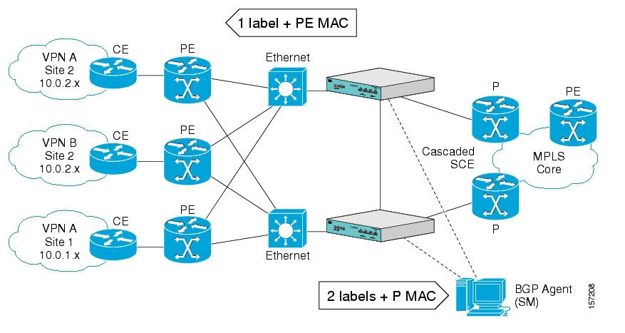
Following are the general topology requirements for MPLS/VPN support:
The SCE platform is placed in the network between the P routers (Provider MPLS core) and the PE (Provider Edge) routers.
The subscriber side of the SCE platform is connected toward the PE router.
The network side of the SCE platform is connected toward the P router.
The BGP LEG is installed on the SM, and is placed somewhere in the network.
It speaks with the SCE platform through the management IP.
In a cascade installation:
The two SCE platforms are connected to each other via the cascade interfaces.
The data link between the P and the PE is connected via the other interfaces on each SCE platform, as described above:
Subscriber side of each SCE platform connected toward the PE router
Network side of each SCE platform connected toward the P router
The following drawing depicts a typical cascade installation.
The system supports:
2015 MPLS/VPN subscribers
57,344 different labels (including upstream and downstream, and including the bypassed VPNs)
256 PEs per SCE platform
4 interfaces per PE
Mutually exclusive system modes
When the system works in MPLS/VPN mode, the following modes are not supported:
Other tunneling modes (MPLS/TE, L2TP, VLAN, etc…).
TCP Bypass-establishment
DDoS
Flow Filter TOS rules – When the MPLS/VPN feature is activated, the flow filter mode is automatically switched to tunnel-id. When the feature is de-activated, the flow filter mode remains tunnel-id.
This provides easy configuration of MPLS/VPN. To assure correct and consistent configuration of the TOS/Tunnel-ID mode, the system does not allow configuration of TOS based rules when in tunnel-ID and vice versa
Number of MPLS labels
The choice of the unique VPN site must be based on the BGP label only. The BGP label must be the innermost label.
The MPLS/VPN solution supports various combinations of labels. See Additional MPLS Pattern Support .
The system does not support VPNs for which other MPLS-related features, such as MPLS-TE or MPLS-FRR, are enabled.
Subscriber-related limitations
The following subscriber-related limitations exist in the current solution:
The SM must be configured to operate in PUSH mode.
VLAN subscribers cannot be used.
Two sites of the same VPN must be aggregated into one subscriber if the following conditions are both true:
They are both connected to the same SCE platform
They both communicate with a common remote site using the same upstream labels and P router.
TCP related Requirements
Number of Upstream TCP Flows – There must be enough TCP flows opening from the subscriber side on each PE-PE route in each period of time. The higher the rate of TCP flows from the subscriber side, the higher the accuracy of the mechanism can be.
This chapter explains how to configure MPLS/VPN support. Both the SCE platform and the SM must be properly configured.
In order for MPLS/VPN support to function, the environment must be configured correctly, specifically the following are required:
All other tunneling protocols must be configured to the default mode.
VLAN support must be configured to the default mode.
Check the running configuration to verify no user-configured values appear for tunneling protocols or VLAN support, indicating that they are all in default mode.
Use the following command to check the current running configuration for configuration of the tunneling/VLAN environment:
From the
SCE#prompt, typeshow running-configand press Enter.
If VLAN or tunneling support is in default mode, skip the relevant step in the following procedure.
To configure the MPLS environment, complete the following steps:
Configure VLAN support to default mode:
From the
SCE(config if)#prompt, typedefault vlanand press Enter.Disable all other tunneling protocol support:
From the
SCE(config if)#prompt, typeno IP-tunneland press Enter.Enable the MPLS auto-learning mechanism.
From the
SCE(config if)#prompt, typeMPLS VPN auto-learnand press Enter.
Note
All subscribers with tunnel mappings must be cleared in order to change the tunneling mode. If the connection with the SM is down, use the no subscriber all with-tunnel-mappings CLI command (see Removing Subscribers with Tunnel Mappings).
There are three main steps to configure the SCE platform for MPLS/VPN support:
Correctly configure the MPLS tunneling environment, disabling all other tunneling protocols, as well as disabling VLAN support.
Configure the MAC resolver.
Define all PE routers, specifying the relevant interface IP addresses necessary for MAC resolution.
Each PE router that has managed MPLS/VPN subscribers behind it must be defined using the following CLI command.
The following options are available:
PE-ID — IP address that identifies the PE router.
Interface-IP — Interface IP address for the PE router. This is used for MAC resolution.
At least one interface IP address must be defined per PE router.
Multiple interface IP addresses may be defined for one PE router.
In the case where the PE router has multiple IP interfaces sharing the same MAC address, it is sufficient to configure just one of the PE interfaces
vlan — A VLAN tag can optionally be provided for each interface IP.
Two interfaces cannot be defined with the same IP address, even if they have different VLAN tags. If such a configuration is attempted, it will simply update the VLAN tag information for the existing PE interface.
To define the PE routers in the system, use the following command for each PE router:
From the
SCE(config if)#prompt, typeMPLS VPN PE-ID<IP> Interface-IP <IP> [vlan <vlan>][Interface-IP <IP> [vlan <vlan>]]and press Enter.
To remove a specified interface from a PE router, use the following command:
From the
SCE(config if)#prompt, typeno MPLS VPN PE-ID<IP>Interface-IP<IP>and press Enter.
Use these commands to remove one or all defined PE routers.
Please note the following:
You cannot remove a PE if it retains any MPLS mappings. You must logout the VPN before removing the router it uses.
Removing the last interface of a PE router removes the router as well. Therefore, you must logout the relevant VPN in order to remove the last interface.
Likewise, all MPLS VPNs must be logged out before using the
no PE-Databasecommand below, since it removes all PE routers.
The MAC resolver allows the SCOS to find the MAC address associated with a specific IP address. The MAC resolver must be configured when the SCE platform operates in MPLS/VPN mode, in order to translate the IP addresses of the provider edge router interfaces to their respective MAC addresses.
The MPLS/VPN mode needs the MAC resolver, as opposed to the standard ARP protocol, because ARP is used by the management interface, while MPLS/VPN uses the traffic interfaces of the SCE platform, which ARP does not include.
The MAC resolver database holds the IP addresses registered by the clients to be resolved. The IP addresses of the routers are added to and removed from the database in either of two modes:
Dynamic mode (default)
In this mode, the system listens to ARP messages of the configured PE interfaces, and this way it stays updated with their MAC addresses. There is no configuration required when operating in dynamic mode.
Benefit: it works even if the MAC address of the PE interface changes.
Drawback: depending on the specific network topology, the MAC resolution convergence time may be undesirably long.
Static mode
In this mode, the MAC address of each PE router must be explicitly defined by the user.
Benefit: no initial delay until IP addresses converge
Drawback: PE interface is not automatically updated via ARP updates; therefore it doesn't automatically support cases where the MAC address changes on the fly.
However, for statically configured MAC addresses, a user log message appears when the system detects that the MAC address changed. This can be used by the operator to configure the new address.
These two modes can function simultaneously; therefore selected PE routers can be configured statically, while the rest are resolved dynamically
For more information regarding the MAC resolver, refer to the Cisco Service Control Engine Software Configuration Guide.
Use this command to add a static IP entry for a PE router to the database.
The following options are available:
ip address — The IP address entry to be added to the database.
vlan tag — VLAN tag that identifies the VLAN that carries this IP address (if applicable).
mac address — MAC address assigned to the IP address, in xxxx.xxxx.xxxx format.
Use this command to remove a static IP entry for a PE router from the database.
The following options are available:
ip address — The IP address entry to be removed from the database.
vlan tag — VLAN tag that identifies the VLAN that carries this IP address (if applicable).
mac address — MAC address assigned to the IP address, in xxxx.xxxx.xxxx format.
There are two main steps to configure the SM for MPLS/VPN support:
Edit the p3sm.cfg configuration file to specify the field in the BGP messages that should be used by the SM for MPLS-VPN identification.
Install and configure the BGP LEG (refer to the SCM SM MPLS/VPN BGP LEG Reference Guide).
The SM configuration file, p3sm.cfg must be configured to specify the field in the BGP messages that should be used by the SM for MPLS-VPN identification.
To configure the SM for MPLS/VPN support, complete the following step:
Add the following section to the p3sm.cfg configuration file:
# The following parameter enables SM operation with MPLS-VPN support.
[MPLS-VPN] # The following parameter determines field in the BGP messages that should be used
# for MPLS-VPN identification, in correlation to the MPLS-VPN mappings that were
# previously set to the SM.
# possible values: "rd" or "rt".
# (default: rt)
vpn_id=rt
An optional parameter may be turned on to facilitate troubleshooting the BGP LEG installation. This parameter turns on detailed logging of messages received from the BGP LEG. It should only be turned on when necessary for troubleshooting and should always be turned off for normal operation of the system.
To configure the SM for troubleshooting MPLS/VPN support, complete the following step:
Add the following section to the p3sm.cfg configuration file:
# The following parameter turns on detailed logging of messages received from the BGP LEG
# should be changed to true only during troubleshooting
# (default: false)
log_all=true
This chapter explains how to manage MPLS/VPN support.
The SCE platform CLI allows you to do the following:
Display subscriber mappings
Monitor subscriber counters
Monitor PE routers
Monitor bypassed VPNs
Use the following Viewer commands to display subscriber mappings. These commands display the following information:
All the MPLS/VPN mappings for a specified subscriber
The number of MPLS/VPN mappings for a specified subscriber
The subscriber to whom a specified downstream mapping (PE loopback IP address & BGP label) is mapped
To display all the MPLS/VPN mappings for a specified subscriber, use the following command:
From the
SCE#prompt, typeshow interface LineCard 0 subscriber name<name> mappingsand press Enter.
Sample output:
Subscriber 'SubscriberX_1122334455' mappings:
Downstream MPLS Mappings:
PE-ID = 1.1.1.1 Mpls Label = 30
PE-ID = 1.1.1.1 Mpls Label = 256
PE-ID = 1.1.1.1 Mpls Label = 2
PE-ID = 1.1.1.1 Mpls Label = 3
PE-ID = 1.1.1.1 Mpls Label = 4

=====> Total Downstream Mappings: 5
Upstream MPLS Mappings:
Upstream MPLS label: (MAC = 00:50:04:b9:c8:a0 BGP label = 0x14, LDP Label = 0xa)

=====> Total Upstream Mappings: 1
The keyword "mappings" limits the output to the MPLS/VPN mapping information only. If the keyword is not used, all subscriber information is displayed, including the mappings.
To display only the number of MPLS/VPN mappings for a specified subscriber, use the following command:
From the
SCE#prompt, typeshow interface LineCard 0 subscriber name<name> mappings | include Totaland press Enter.
Sample output:
=====> Total Downstream Mappings: 5 =====> Total Upstream Mappings: 1
Use this command to remove all learned upstream labels of a specified VPN subscriber.
This command, in effect, causes early label aging. Clearing the mappings allows relearning; labels will probably be quickly relearned after they have been cleared. Therefore, this command is useful when you want to update the mappings without waiting for the standard aging period.
From the
SCE(config if)#prompt, typeno subscriber name<name> mapping upstream mpls alland press Enter.
Use the following Viewer command to display subscriber counters, including those related to MPLS/VPN mappings.
When MPLS/VPN subscribers are enabled, the following related counters appear in addition to the basic subscriber counters:
MPLS/VPN subscribers:
Current number of MPLS/VPN subscribers
Maximum number of MPLS/VPN subscribers
MPLS/VPN subscribers are also counted in the general subscribers counters, but the general subscribers maximum number does not apply to MPLS/VPN subscribers, which have a smaller maximum number.
MPLS/VPN mappings:
Current number of used MPLS/VPN mappings
Maximum number of MPLS/VPN mappings
Note that these values reflect the total number of mappings, not just the mappings used by MPLS/VPN subscribers. Bypassed VPNs also consume MPLS/VPN mappings.
From the
SCE#prompt, typeshow interface LineCard 0 subscriber db countersand press Enter.
Sample Output:
Current values:
===============
Subscribers: 2 used out of 99999 max.
Introduced subscribers: 2.
Anonymous subscribers: 0.
Subscribers with mappings: 2 used out of 99999 max.
IP mappings: 0 used.
MPLS/VPN subscribers are enabled.
MPLS/VPN mappings: 2 used out of 57344 max.
MPLS/VPN subscribers: 2 used out of 2015 max.
Subscribers with open sessions: 0.
Subscribers with TIR mappings: 0.
Sessions mapped to the default subscriber: 0.
Peak values:
============
Peak number of subscribers with mappings: 2
Peak number occurred at: 14:56:55 ISR MON November 7 2005
Peak number cleared at: 13:29:39 ISR MON November 7 2005
Event counters:
===============
Subscriber introduced: 2.
Subscriber pulled: 0.
Subscriber aged: 0.
Pull-request notifications sent: 0.
State notifications sent: 0.
Logout notifications sent: 0.
Subscriber mapping TIR contradictions: 0.
Note
The maximum number of subscribers when MPLS/VPN support is enabled is actually the maximum noted in the MPLS/VPN subscribers line (2015), rather than the maximum noted in the first line.
Use the following Viewer command to display MPLS/VPN information.
From the
SCE#prompt, typeshow interface LineCard 0 mpls vpnand press Enter.
Sample Output:
MPLS/VPN auto-learn mode is enabled.
MPLS/VPN subscribers: 0 used out of 2015 max
Total HW MPLS/VPN mappings utilization: 0 used out of 57344 max
MPLS/VPN mappings are divided as follows:
downstream VPN subscriber mappings: 0
upstream VPN subscriber mappings: 0
non-vpn upstream mappings: 0
downstream bypassed VPN mappings: 0
upstream bypassed VPN mappings: 0
Use the following Viewer commands to monitor PE routers. These commands provide the following information:
Configuration of all currently defined PE routers.
Configuration of a specified PE router.
The SM CLU allows you to do the following:
Add, remove, and display MPLS/VPN mappings for a specified subscriber (VPN)
Clear all MPLS/VPN mappings from the SM database
Use the p3subs utility to manage subscriber MPLS/VPN mappings.
The following options are available:
Subscriber-Name — The name assigned to the VPN when it was added as a subscriber.
RT@PE-IP — The mapping to be assigned to the subscriber/VPN. Multiple mappings can be specified using a comma.
RT = the route target of the VPN, specified using the ASN:n notation or the IP:n notation
Note that the Route Distinguisher may be specified rather than the route target
PE-IP = the loopback IP of the PE router connected to that VPN
To manage individual subscriber MPLS/VPN mappings, use the following command:
From the shell prompt, type a command having the following general format:
p3subs<operation> --subscriber=<Subscriber-Name> --mpls-vpn=<RT@PE-IP>[--additive-mapping]
The following table presents all the p3subs operations relevant to managing mappings.
Table 4.1. p3subs Mapping Operations
|
Operation |
Description |
|---|---|
|
--set |
Add/update a subscriber. If the mapping exists, replaces the existing mapping, unless the additive-mapping option is used. |
|
--remove-all-mappings |
Removes all the mappings of specified subscriber. |
|
--remove-mappings |
Removes specified mapping of specified subscriber. |
Table 4.2. p3subs Mapping Options
|
Operation |
Description |
|---|---|
|
--additive-mapping |
Adds the specified mappings to the existing ones (instead of replacing the existing mappings when this option is not used). Used with the set operation. |
SNMP support for MPLS/VPN auto-learn is provided in two ways:
MIB variables
SNMP traps
The mplsVpnAutoLearnGrp MIB object group (pcubeSEObjs 17) contains information regarding MPLS/VPN auto-learning.
The objects in the mplsVpnAutoLearnGrp provide the following information:
maximum number of mappings allowed
current number of mappings
For more information, see the "Proprietary MIB Reference" in the Cisco Service Control Engine Software Configuration Guide.
There is one MPLS/VPN-related trap:
mplsVpnTotalHWMappingsThresholdExceeded (pcubeSeEvents 45)
In order to provide online notification of a resource deficiency, when the system reaches a level of 80% utilization of the hardware MPLS/VPN mappings, a warning message appears in the user log, and this SNMP trap is sent.
Both the warning and the trap are sent for each 100 mappings that are added after the threshold has been exceeded.