|
|

This quick start guide provides basic installation and configuration instructions that can make your Cisco 6920 RateMux multiplexer operational in a short period of time.
These instructions include a basic configuration using some default settings. To use advanced configuration options, refer to the Cisco 6920 RateMux Multiplexer Installation and Configuration Guide. For the latest information regarding software releases, refer to the Release Notes for the Cisco 6920 RateMux Multiplexer.
 |
Note Cards in the Cisco 6920 chassis are not hot-swappable. The Cisco 6920 must be powered down before cards are removed and replaced. |
The eight card slots on the Cisco 6920 chassis are addressed from 0 to 7, starting from the left side of the chassis. The connectors for inputs and outputs are addressed when using the RateMux Manager GUI from the top of the card to the bottom of the card starting with 0 (see Figure 1).
For example, a complete address of an input might be Slot 2, Module 1, which identifies the second connector from the top of the card located in the third card slot in the chassis.
 |
Note This convention, rather than the labeling on the cards, must be used to address specific slots and connectors. |


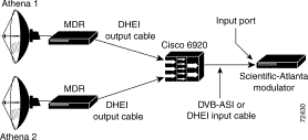
There are three primary ways to access the Cisco 6920. Each has a different purpose.
1. The serial connection uses HyperTerminal and is required when the IP address of the Cisco 6920 is unknown.
2. Connect.exe is an application file included with the Cisco 6920 software bundle. It uses Ethernet and requires an IP address to connect. Connect.exe allows access to the diagnostic menus similar to those seen when using HyperTerminal. Connect.exe is primarily used for software upgrades and environmental parameter changes and is not required for quick start.
3. Web-based configuration requires an Ethernet connection and uses Netscape Communicator or Microsoft Internet Explorer to connect to the Cisco 6920 using its IP address. The browser connects to the RateMux Manager GUI and is the usual mode for configuring and monitoring the Cisco 6920.
 |
Note A Dynamic Host Configuration Protocol (DHCP) server also can be used. Refer to the Cisco 6920 RateMux Multiplexer Installation and Configuration Guide for further information. |
The following sections provide details on how to connect to the Cisco 6920 using each of the three methods.
 |
Tip If the IP address is unknown, you can try the default address 10.0.0.200. |
Connect a regular 9-pin serial cable from the serial communications port of the connecting computer to the debug connector on the PowerPC card in the Cisco 6920. This is a straight-through cable, also referred to as an extension serial cable.
 |
Note Do not use a null modem cable or you will not be able to connect. |
Step 2 Power on the Cisco 6920 and use the Call option in HyperTerminal to start the session within 10 seconds.
Step 3 After starting the session, press Enter on the connecting computer until the Cisco 6920 screen dump appears (5 to 60 seconds) and the IP address of the Cisco 6920 is visible.
Step 4 While connected in HyperTerminal, you can change the IP address and the name of the Cisco 6920.
Step 2 From the menu, choose C Environmental Parameters and FLASH Partitions.
Step 3 Choose B Environmental Parameters.
Step 4 Choose B Change Environmental Parameters.
Step 5 You will be prompted for each parameter. Press Enter to skip any parameters that do not need to be changed. When the IP Address parameter appears, enter the new IP address and press Enter.
Step 6 After skipping over the remaining options, press S then press Enter to save the changes.
Step 7 Power cycle the Cisco 6920 and use the new IP address.
Step 2 When the Host Name option appears, enter the new name.
Step 3 After skipping over the remaining options, press S then press Enter to save the changes.
Step 4 Power cycle the Cisco 6920.
Step 2 Make sure that the connecting computer's IP domain matches that of the Cisco 6920.
Step 3 Connect an Ethernet cable from the Cisco 6920 to the connecting computer. Use a crossover cable if you are connecting directly.
 |
Note Shielded Ethernet cables must be used for FCC compliance. |
Step 4 Locate the application file connect.exe included in the software bundle and launch it.
Step 5 Click Connection on the pull-down menu, then click connect.
Step 6 Enter the Cisco 6920 IP address in the window. Don't click OK.
Step 7 Power on the Cisco 6920. Within 10 seconds, click OK. Connection should occur in 5 to 60 seconds.
Step 2 Make sure the connecting computer's IP domain matches that of the Cisco 6920.
Step 3 Connect an Ethernet cable from the Cisco 6920 to the connecting computer. Use a crossover cable if you are connecting directly.
 |
Note Shielded Ethernet cables must be used for FCC compliance. |
Step 4 If the Cisco 6920 is not running, power it on and wait for 3 to 5 minutes for it to initialize.
Step 5 Launch Netscape or Microsoft Internet Explorer and enter the Cisco 6920 IP address. The RateMux Manager GUI appears.
Step 2 Click Chassis Configuration and verify the Cisco 6920 name and IP address
Step 3 Scroll to Board Type and verify that all the hardware is present.
Step 4 In the Software Modules section, verify that the software on all boards is the same version and is current.
Step 5 In the Stream Type section, select the Output Video Stream Type:
Digital Signal Processor (DSP) allocation must be performed before selecting channels.
Step 2 Click Chassis Configuration.
Step 3 Scroll to the System DSP CPU Bandwidth Allocation section. (See Figure 4.)
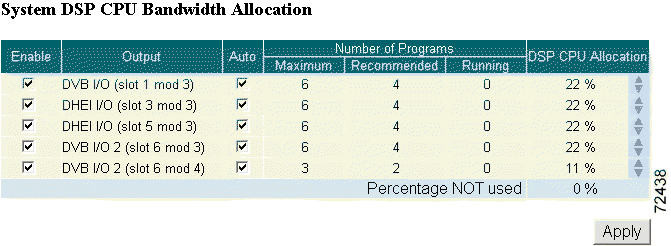
Step 4 Use the Enable check boxes to designate which output ports will be used and will require DSPs. All outputs are enabled (checked) by default, and DSPs are assigned evenly among all of them.
 |
Note Outputs that have programs assigned to them cannot be disabled (unchecked). Clear the configuration before disabling them. |
Step 5 DSPs for disabled outputs become available for allocation and are moved to the "Percentage NOT used" row. Use the up arrows in the far right column to move unused DSPs to outputs. Click Apply to make the changes.
 |
Note The output DSP also is available as a demux DSP in the pool of available DSPs. |
Step 6 Check the Auto check box to automatically allocate programs to DSPs assigned to that output when a configuration is applied.
 |
Note Service is disrupted on this output when the DSP calculation is applied. |
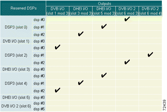
DSP to output assignments can be viewed on the table directly below the DSP Allocation window. (See Figure 5.)
Step 2 Click Program Select Output Config and scroll to the Edit Output Configuration section. (See Figure 6.)
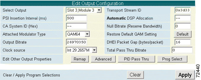
Step 3 The Select Output field displays the slot and connector of the output. Use the pull-down menu to select the proper card for your configuration.
Step 4 The Transport Stream ID field is filled in automatically. If you have specific requirements for a transport stream ID, leave this field blank or use any value that was previously automatically entered,
Step 5 The PSI Insertion Interval field indicates the rate (in milliseconds) at which PSI data is being injected into the video stream. Enter the desired rate.
 |
Note The recommended PSI Rate is 200. This conforms to Motorola PSI requirements. |
Step 6 The CA System ID field displays (in hexadecimal) the Conditional Access System ID descriptor needed by the Conditional Access vendor. Change this value by entering a new value (such as AB 34) in the field. Entering two dashes (--) indicates that the original setting should be kept. To delete the CA descriptor, enter either del or Del, then click Apply.
Step 7 The Null Bitrate (Reserve Bandwidth) field indicates the number of NULL packets (in bits per second) being inserted into the video stream. Enter the bandwidth needed for any data insertion downstream from the Cisco 6920.
 |
Note The recommended Null rate is 300000 for systems that have Conditional Access systems on the output of the Cisco 6920. |
Step 8 Use the Attached Modular Type pull-down menu to choose either quick configuration option (QAM64 or QAM256). For each selection, the Output Bitrate and Byte Gap are automatically calculated and the values inserted into their fields.
 |
Note Analog channel bandwidth is assumed to be a default of 6 MHz. |
Step 9 If any of the automatically calculated fields are changed after the quadrature amplitude modulation (QAM) setting is selected, click Restore Default QAM Setting to return the values to the default settings.
Step 10 If audio-only programs (such as DMX or Music Choice) are to be passed through, calculate the peak bit rate of the sum of all these programs selected for passthrough and enter it in the Total PassThru Bitrate field.
 |
Note Music Choice recommends a PassThru Bitrate of 13,500,000 when configuring all Music Choice programs in a single output. If the Music Choice programs (with still-frame video) are split between outputs, then use 257 kbps for each program plus 2.3 Mbps for the video stream maximum burst rate. |
Step 11 Click Apply to make changes or Clear to clear program selections.
Step 2 Select programs to be included in the output.
 |
Note Click Clear to deselect all programs in the list. Clicking clear does not restore default output parameters or original packet identifier (PID) and program numbers for each input. |
Step 3 To resolve PID conflicts, click Force Map.
Step 4 If Music Choice programs are selected, click Advanced to display the Advanced page.
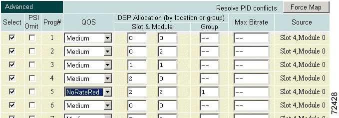
Step 5 Modify the quality of service (QoS) for each Music Choice program to pass through as shown in Figure 7.

Step 6 Click Apply to save the configuration.
Each high-definition (HD) program needs a DSP assigned to it. If any other programs are sharing the same DSP as the HD program, unexpected results can occur. Follow these steps to configure an HD program:
Step 2 Scroll to the System DSP CPU Bandwidth Allocation window.
Step 3 Determine which output the HD program will use and be sure that Enabled is selected and Auto is not selected.
Step 4 Click Program Select Output Config, and scroll to the Program Select display. Be sure that Select Output is set to the output the HD program will be on.
Step 5 Click Advanced.
Step 6 Locate the HD program. In the QOS column, use the pull-down menu and select NoRateRed (no rate reduction).
Step 7 Assign the HD program a unique group number under the Group column (see Figure 8).
Step 8 Click Apply to save the configuration.
 |
Note In Figure 8, the HD program is Program 5 set to NoRateRed in DSP Group 1. |

| Signal | Pin | Pin | Signal |
|---|---|---|---|
Transmit Data | 1 | 3 | Receive Data (RxD+) |
Transmit Data | 2 | 6 | Receive Data (RxD-) |
Receive Data | 3 | 1 | Transmit Data (TxD+) |
- | 4 | 4 | - |
- | 5 | 5 | - |
Receive Data | 6 | 2 | Transmit Data (TxD-) |
- | 7 | 7 | - |
- | 8 | 8 | - |
![]()
![]()
![]()
![]()
![]()
![]()
![]()
![]()
Posted: Tue May 21 18:25:14 PDT 2002
All contents are Copyright © 1992--2002 Cisco Systems, Inc. All rights reserved.
Important Notices and Privacy Statement.