|
|

This chapter describes how to deploy a site, object, or network. Deployment is the term used within CMNM to mean the addition of objects to the CEMF network model. CMNM provides two methods to deploy Cisco MGC nodes and subobjects:
Seed file configuration requires that you define the Cisco MGC network or object (or a portion of it) in an external file that is read by CMNM. Based on the contents of this file, CMNM deploys the file to Cisco MGC nodes and subnodes.
You can also manage software images and configurations on the Cisco MGC node devices. For more information, see the "Managing Software Images and Configurations" section.
IDs and passwords must be consistent across all of the devices being deployed, or deployment does not fully succeed. As a result, you must use an additional CEMF dialog to specify the correct login ID and password for the devices. In addition, you have to manually discover the logical connectivity network for those devices.
Anytime a password is changed on a device, you must make a corresponding change in CMNM. Otherwise CMNM's saved passwords will not match those on the devices; polling and connectivity network discovery fail. The same is true for SNMP community strings on the Cisco SLTs and LAN switch.
For bulk deployment, you can use a deployment seed file. This seed file contains all of the information necessary to deploy an entire Cisco MGC network.
This seed file contains the IP addresses of all of the devices in the Cisco MGC network, plus the relationship (hierarchy) between the devices. Given this file, CMNM is able to automatically deploy all the elements in the network.
The data in the seed file includes, but is not limited to the:
A sample seed file is shown in Example 6-1.
The seed file allows you to specify a number of attributes for each device. In some cases these attributes are required. Optional attributes assume a default value if they are not specified. The default values are specified in the seed file deployment dialog.
The supported attributes are described in Table 6-1.
Each Cisco MGC node can have, at most, one active host. You can define a maximum of two hosts per
Cisco MGC node, one representing the active Cisco MGC host and the other the standby Cisco MGC host. You do not have to define which host is active or standby; this is determined automatically by CMNM.
You must specify the name for each Cisco MGC node. Optionally, you can then specify names for the other elements. If no name is specified, a default name is generated. In addition, you can specify account information about the various devices: login IDs, passwords, and SNMP community strings. Each value is optional and, if missing, is initialized by the corresponding value in the seed file deployment dialog.
To perform seed file deployment, you launch a dialog from a MGC-Node-View node or other type of CEMF object. This dialog prompts you for the name of the seed file and the login ID and password for the Cisco MGC host devices. You also specify SNMP read- and write-community passwords for the Cisco SLT and LAN switch.
When a device is deployed, it is placed into the Physical containment tree based on the physical location of the devices. That is, all devices in Chicago are placed under a region or site object named Chicago. When generating the seed file, you use the location attribute to specify where in the Physical containment tree each device should be deployed.
If you do not specify a physical location (the location attribute is optional), the objects are deployed in the same location as its logical parent. Otherwise, the object is deployed in a site named Default. If you specify a physical location, the devices are deployed under that object accordingly. If the specified location does not exist, CMNM automatically deploys a region object with the specified location name.
Cisco MGC node objects are not physical devices and, as such, are not deployed into the Physical containment tree. However, the seed file lets you specify a location for Cisco MGC nodes. This is done so dependent children of the Cisco MGC node can, by default, be placed in the specified location. For example, assume that you specify that a Cisco MGC node is in the site Cincinnati. All of its children that do not specifically specify a location are, by default, placed in the Cincinnati site.
To deploy a network using a seed file:
Step 2 Right-click to display the pull-down menu, select Deployment, then Deploy Network Seed File.
 |
Note Only one Cisco MGC node can be deployed at a time. Each requires a seperate seed file. |
You see the screen in Figure 6-1.
Step 3 Enter a filename in the seed file Filename field.
Step 4 If any fields for a type of device are not specified in the seed file, you can enter account information for each type of device on this screen.
Step 5 To enter advanced information, click the Advanced tab.
You see the screen in Figure 6-2.
Step 6 You can enter SNMP configuration parameters. You can also export the current configuration as a seed file or an inventory file.
An inventory file contains a description of all of the devices in the Cisco MGC network, including:
The inventory file lists all of the Cisco MGC node devices in the network. For each Cisco MGC node device, information about each sub-device in the node is listed. For example:
The attributes exported for the various device types are shown in Table 6-2.
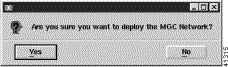
Step 7 When you are finished, click the Seed File tab to return to the screen in Figure 6-1 and click Deploy.
You see the screen in Figure 6-3.
Step 8 Click Yes.
The deployment wizard is the graphical user interface (GUI) used to create new objects representing the network elements to be managed with CMNM. The deployment wizard uses deployment profiles to prompt you for the information that is required by the deployment process. It can be accessed from different windows within CMNM as outlined below.
|
Note Only one deployment wizard can be open at any time. If you attempt to open a second
wizard, you see the message: The Deployment Wizard is already active. Select it from the Window menu, or check for iconified or hidden windows. Complete the first deployment task before proceeding. |
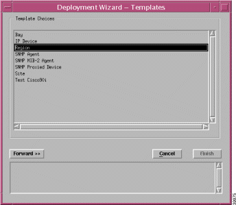
CMNM defines a number of templates that allow you to manually configure Cisco MGC nodes and subobjects. The templates include:
The deployment wizard reads the templates and presents screens prompting for information about the devices.
Table 6-3 describes deployment attributes.
To open the deployment wizard:
Step 2 From the pop-up menu, select Deployment, then select Deploy Generic Objects.
You see the screen in Figure 6-4.
Step 2 Click to select a MGC-Node-View icon from the left panel of the Map Viewer window.
Step 3 Right-click the MGC-Node-View icon, select Deployment, then Deploy MGC Node, as shown in Figure 6-5.
You see the screen in Figure 6-6.
Step 4 Enter the name of the Cisco MGC node (no spaces). Click Forward.
You see a screen that summarizes the deployment you have created and allows you to commit or reject the deployment.
Step 5 Click Finish.
You are informed if deployment has been successful. A Cisco MGC icon appears on the right pane of the Map Viewer window.
Step 6 Deploy Cisco MGC hosts by following the instructions in the "Deploying a Cisco MGC Host" section.
Step 7 Deploy Cisco SLTs by following the instructions in the "Deploying a Cisco SLT" section.
Step 8 Deploy LAN switches by following the instructions in the "Deploying a LAN Switch" section.
Step 9 Deploy Cisco MGX 8260s by following the instructions in the "Deploying a Cisco MGX 8260" section.
Step 10 Deploy the optional Billing and Measurements Server by following the instructions in the "Deploying a Billing and Measurements Server (BAMS)" section.
Step 2 Expand the MGC-Node-View icon and click to select a Cisco MGC node icon from the left panel of the Map Viewer window.
Step 3 Right-click the MGC node icon and select Deployment, then Deploy MGC Node Component.
Step 4 Click Deploy an MGC Host and click Forward.
Step 5 Enter data for the host. See Table 6-3 for descriptions of the fields. Click Forward.
Step 6 Select a relationship and click Forward.
Step 7 Click Finish.
A Common-Host icon appears on the right pane of the Map Viewer window. Also, a host icon appears on the left panel as a child node of the common-host node.
Step 2 Expand the MGC-Node-View icon and click to select a Cisco MGC node icon from the left panel of the Map Viewer window.
Step 3 Right-click the MGC node icon and select Deployment, then Deploy MGC Node Component.
Step 4 Click Deploy an SLT and click Forward.
Step 5 Enter data for the Cisco SLT. See Table 6-3 for descriptions of the fields. Click Forward.
Step 6 Select a relationship and click Forward.
Step 7 Click Finish.
A Cisco SLT icon appears on the right pane of the Map Viewer window.
Step 2 Expand the MGC-Node-View icon and click to select a Cisco MGC node icon from the left panel of the Map Viewer window.
Step 3 Right-click the MGC node icon and select Deployment, then Deploy MGC Node Component.
Step 4 Click Deploy a 2900 XL Switch or Deploy a Catalyst 5500 Switch and click Forward.
Step 5 Enter data for the LAN switch. See Table 6-3 for descriptions of the fields. Click Forward.
Step 6 Select a relationship and click Forward.
Step 7 Click Finish.
A LAN switch icon appears on the right pane of the Map Viewer window.
Step 2 Click to select a MGC-8260-View icon from the left panel of the Map Viewer window.
Step 3 Right-click the MGC-8260-View icon and select Deployment, then Deploy MGX 8260.
Step 4 Enter data for the media gateway. See Table 6-3 for descriptions of the fields. Click Forward.
Step 5 Select a relationship and click Forward.
Step 6 Click Finish.
A media gateway icon appears on the right pane of the Map Viewer window.
Step 2 Click to select a BAMS-View icon from the left panel of the Map Viewer window.
Step 3 Right-click the BAMS-View icon and select Deployment, then Deploy BAMS.
Step 4 Enter data for the BAMS server. See Table 6-3 for descriptions of the fields. Click Forward.
Step 5 Select a relationship and click Forward.
Step 6 Click Finish.
An icon appears on the right pane of the Map Viewer window.
When a Cisco SLT, LAN switch, Cisco MGC host, or BAMS is deployed, its subrack components are queried and deployed. The types of subrack components, as well as their relationships, differ based on the type of device.
CMNM performs the subrack discovery of various types of devices. When a device is deployed, CMNM checks the OID of the device. If possible, CMNM performs custom subrack discovery based on the device type. Otherwise, a generic discovery mechanism is used.
The various subrack discovery mechanisms are described in the following sections.
|
Note CMNM automatically discovers each device at an interval you may specify and keeps track of the time that each device was last discovered. When the specified interval has elapsed, CMNM automatically rediscovers the device. |
The Cisco MGC host and BAMS discovery mechanism processes the ifTable of the device and deploys an object to represent each (supported) interface. BAMS also uses the CIAgent system component discovery mechanism. In addition, an object representing each (non-loopback) IP address is deployed as a child of its corresponding interface as shown in Figure 6-7.
This subrack discovery mechanism is used for the Cisco MGC host, BAMS, and any unknown or unsupported device that is deployed.
For devices that support the CIAgent SNMP Agent (Cisco MGC host and BAMS), components are deployed that represent logical components of the UNIX system, as shown in Table 6-4
The Cisco 2611 series auto-discovery mechanism expands slightly on the Cisco MGC host and BAMS discovery mechanism. First, all TDM (DS1) interfaces are deployed. Second, in a non-V.35 configuration, serial interfaces are placed under their dependent TDM interface. IP address objects are deployed under their corresponding interface.
CMNM also models the three SS7 MTP2 channels on each Cisco SLT. From these channels, you can view current SS7 MTP2 statistics.
CMNM models ports and modules (slots) on the Cisco 2900XL series devices. The Cisco 2900 XL has 24 ports built into the chassis. In addition the Cisco 2900XL has two slots into which different cards can be installed.
During auto-discovery, CMNM retrieves the tables shown in Table 6-5.
Each entry in the c2900ModuleTable is modeled as a switch2900XLSlot object. The attribute SNMP:CISCO-C2900-MIB.c2900ModuleIndex serves as an index into the table.
Each entry in the c2900PortTable is modeled as a switch2900XLPort object. In the CMNM object model, it is placed under its dependent slot. The c2900PortTable is indexed by two attributes, the module index and the port index. The module index indicates on which slot the port resides. Module index zero indicates that the ports are dependent on the chassis, and not on a slot. The attribute c2900PortIfIndex is used to correlate the c2900PortTable to the ifTable.
Each entry in the vtpVLANTable is modeled as a switch2900XLVLAN. In addition, each interface associated with the VLAN is displayed as children of its corresponding VLAN. In order to correlate interfaces from the ifTable to their corresponding VLANS in the vtpVLanTable, CMNM uses the description of the ifTable entry, which is of the form:
where x is the index of the corresponding entry in the vtpVlanTable.
The Cisco 2900XL subrack component appears as shown in Figure 6-9.
CMNM models slots, VLANs, and ports on the Catalyst 5500 series devices. During auto- discovery, CMNM retrieves the tables shown in Table 6-6.
Each entry in the moduleTable is modeled as a switch5500Slot object and every entry in the portTable is modeled as a switch5500Port object. To correlate the information, the attribute portModuleIndex defines the slot on which the port is located and the portIfIndex is used to correlate the portTable to its corresponding interface in the ifTable.
Each entry in the vlanTable is modeled as a switch5500VLAN object. The attribute vlanIfIndex associates each element in the VLAN table to its corresponding interface in the ifTable. The associated interface is shown as a child of its corresponding VLAN.
The SC0 and SL0 interfaces are modeled directly under the chassis object. In the MIB, one interface has a valid IP address while the other has an IP address of 0.0.0.0. While both interfaces are modeled, only the valid IP is shown.
The Catalyst 5500 subrack component is shown in Figure 6-10.
CMNM models and displays the trunking, signaling, and dial plan components associated with the active Cisco MGC host. When CMNM initially discovers a new Cisoc MGC node, it retrieves the configuration for the active Cisco MGC host by telneting into the active host, starting an MML session, and running the prov-exp command. This command puts the current configuration of the Cisco MGC host in a number of flat files as described in Table 6-7.
Table 6-7 Cisco MGC Host Export Files
|
Once exported, the files are transfered back to the management system using FTP and are then parsed by CMNM. Hence CMNM can deploy objects that represent each of the signaling, trunking, and routing components.
CMNM ensures that the EMS database (as provided by CEMF) is synchronized with the underlying network elements. All relevant management data within the EMS is automatically updated on receipt of a modification trap from the various network elements.
The traps in Table 6-8 are used to respond to changes in the network elements.
When CMNM receives a POM:DynamicReconfiguration trap from the active Cisco MGC host, it resynchronizes its view of the connectivity network with that of the device.
CMNM lets you manage software images and configurations on the Cisco MGC node devices. You can:
The following sections detail the support for image and configuration management.
CMNM uses a TFTP server to maintain software images and device configurations. All files that are downloaded to devices come from this TFTP server. Likewise, all backups from the devices are saved to the TFTP server.
The TFTP server makes use of the standard UNIX filesystem and can be maintained by anyone with the proper UNIX permissions. The system administrator is free to place new images or configurations on the server and archive or delete old software images and configurations. CMNM does not provide any explicit support for standard filesystem maintenance functions.
The location of the TFTP directory is found in the INETD configuration file /etc/inted.conf. At startup, CMNM queries the contents of this file to figure out the location of the TFTP directory. By default, the directory (if the entry in the inetd.conf file is commented out) is /tftpboot.
CMNM lets you move IOS images and configurations to and from the Cisco SLT and LAN switch.
copy tftp flash (to copy software image)
copy tftp running-config (to copy running configuration)
copy flash tftp (to copy software image)
copy config tftp (to copy running Catalyst configuration)
copy running-config tftp (to copy running IOS configuration)
To upload or download Cisco SLT and LAN switch configurations:
Step 2 Select one or more devices from the list on the left of the screen.
Step 3 In the Transfer box, enter the information about the Cisco SLT or LAN switch:
Step 4 Indicate at the bottom of the screen whether the device should be rebooted.
Step 5 If you want to schedule the transfer, enter the scheduling information in the Schedule box.
Step 6 When you have finished, click Download or Upload as appropriate.
CMNM lets you upload and download Cisco MGC host configurations to a Cisco MGC host. You can upload BAMS configurations.
The Cisco SLT and LAN switch configurations and images are in a single file. The Cisco MGC host and BAMS configurations and patches are in many different files and directories. Hence when you specify a configuration on the TFTP server, CMNM assumes it is a directory containing all of the necessary data:
The download process performs a number of different steps depending on the type of device and data. In general, the following steps are performed:
Voice Services Provisioning Tool does not let you upload software images. CMNM lets you upload configuration data only from the Cisco MGC host and BAMS.
The configuration upload process performs the following steps:
When downloading a patch to a Cisco MGC host, CMNM performs the following steps:
To upload or download Cisco MGC host configurations or upload a BAMS configuration:
Step 2 Select one or more devices from the list on the left of the screen.
Step 3 In the Transfer box, enter the information about the Cisco MGC hosts or BAMS:
Step 4 If you want to schedule the transfer, enter the scheduling information in the Schedule box.
Step 5 When you have finished, click Download or Upload as appropriate.
![]()
![]()
![]()
![]()
![]()
![]()
![]()
![]()
Posted: Mon Sep 15 17:23:25 PDT 2003
All contents are Copyright © 1992--2003 Cisco Systems, Inc. All rights reserved.
Important Notices and Privacy Statement.