cc/td/doc/product/access/rpsbk
hometocprevnextglossaryfeedbacksearchhelp
PDF

Table Of Contents

Connecting the Cisco RPS

Power Considerations

Connecting Hubs

Connecting Switches

Connecting Routers and the Cisco MC3810 Concentrator


Connecting the Cisco RPS


This chapter provides instructions on connecting your external device to the Cisco RPS. The chapter is divided into the following major sections:

Power Considerations

Connecting Hubs

Connecting Switches

Connecting Routers and the Cisco MC3810 Concentrator

Power Considerations

Before connecting to external devices, read the power warnings below. We recommend that you disconnect all power before beginning.


Note If you want to connect an additional external device to a Cisco RPS that is already powered up, you can do so without interrupting power to the Cisco RPS or any other connected external devices. Be sure to connect your cable to the Cisco RPS first and then to the external device. However, in a redundant-with-reboot configuration, to ensure proper operation, you must power up the switch or hub before powering up the Cisco RPS. Therefore, always connect the switch to AC power before you connect it to the Cisco RPS. Failure to follow the proper power-up sequence can result in incorrect LED displays.


Note A catalyst switch might reload when changing from RPS power to internal power. This can occur on any catalyst switch, except the 3560-E or 3750-E switch, connected to one of the following: Redundant, Power Supplies, PWR 300-AC-RPS-NI, PWR-600-AC-RPS-NI, and RPS2300. To prevent unscheduled downtime, the switch should be powered off during a maintenance window.


Warning Attach only the Cisco RPS (model PWR600-AC-RPS) to the RPS receptacle. To see translations of the warnings that appear in this publication, refer to the Regulatory Compliance and Safety Information document that accompanied this device.


Warning Before performing any of the following procedures, ensure that power is removed from the DC circuit. To ensure that all power is OFF, locate the circuit breaker on the panel board that services the DC circuit, switch the circuit breaker to the OFF position, and tape the switch handle of the circuit breaker in the OFF position. To see translations of the warnings that appear in this publication, refer to the Regulatory Compliance and Safety Information document that accompanied this device.


Warning Before working on a system that has an on/off switch, turn OFF the power and unplug the power cord. To see translations of the warnings that appear in this publication, refer to the Regulatory Compliance and Safety Information document that accompanied this device.


Warning This unit might have more than one power cord. To reduce the risk of electric shock, disconnect the two power supply cords before servicing the unit. To see translations of the warnings that appear in this publication, refer to the Regulatory Compliance and Safety Information document that accompanied this device.


Connecting Hubs

This section provides illustrations and cabling information for connecting the Cisco RPS to the following hubs:

Cisco 1516M hub (HP 10BASE-T Hub-16M) ( Figure 4-1)

FastHub 400 series hubs ( Figure 4-2)


Note The Cisco RPS can also be used with the older FastHub 100, 200, and 300 series hubs.


All hubs can use the one-to-one cable configuration for quasi-redundancy. The FastHub 400 series also supports the option of connecting the AC power cord for redundancy with reboot, although this configuration is not recommended. The use of a Y-cable for full redundancy is not supported.

The HP 10BASE-T Hub-16M does not support redundancy with reboot and does not support use of the Y-cable for full redundancy.

To connect hubs to the Cisco RPS, perform these steps:


Step 1 Disconnect the AC power cord on the hub.

Step 2 Connect one end of the one-to-one cable to the Cisco RPS connector on the hub rear panel. (For connector locations, see Figure 4-1 and Figure 4-2.)

Step 3 Connect the other end of the cable to a Cisco RPS rear-panel connector as shown in Figure 4-3.

Figure 4-1 Cisco 1516M Hub (HP 10BASE-T Hub-16M) Rear Panel

Figure 4-2 FastHub 400 Rear Panel

Figure 4-3 Connecting the One-to-One Cable to the Cisco RPS

Step 4 On the Cisco RPS rear panel, connect an AC power cable to either or both of the power connectors. Use the cable locks on the Cisco RPS to lock the cables in place. (See Figure 4-4.)

Figure 4-4 Connecting the AC Power Cables to the Cisco RPS

Step 5 Connect the other end of the Cisco RPS AC power cable into an AC power outlet.

Step 6 If you are using the redundant-with-reboot configuration (not recommended), power up the switch by connecting the hub AC power cord to an AC power outlet.


Note If you use the redundant-with-reboot configuration, always power up the hub before you power up the Cisco RPS.


Step 7 Power up the Cisco RPS. There is one power switch for each AC input power module. Make sure that the power switch is in the ON (|) position for each AC power module used. (See Figure 4-5.)

Figure 4-5 Powering Up the Cisco RPS

The Cisco RPS provides power in 10 to 15 seconds. The Cisco RPS is working properly when all its front-panel LEDs are solid green. If the external device does not power up, refer to "Troubleshooting the Cisco RPS."


Connecting Switches

The Catalyst 1900 series and Catalyst 2820 series switches and the Catalyst 2900 series and Catalyst 3500 series XL switches can use:

One-to-one cable for quasi-redundancy

or

One-to-one cable with the switch AC power cable connected for redundancy with reboot (not recommended)

To connect switches to the Cisco RPS, perform these steps:


Step 1 Disconnect the AC power cord on the switch.

Step 2 Connect one end of the one-to-one cable to the Cisco RPS connector on the switch rear panel. (For connector locations, see Figure 4-6 through Figure 4-12.)

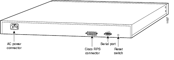
Figure 4-6 Catalyst 1900 Switch Rear Panel

Figure 4-7 Catalyst 2820 Switch Rear Panel

Figure 4-8 Catalyst 2912 XL, Catalyst 2924 XL, and Catalyst 2924C XL Switch Rear Panel

Figure 4-9 Catalyst 2912M XL and Catalyst 2924M XL Switch Rear Panel

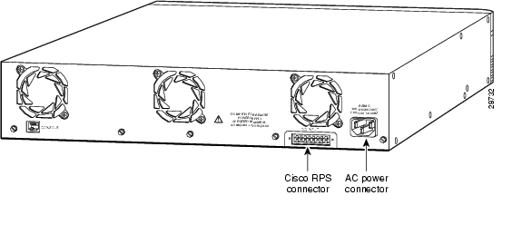
Figure 4-10 Catalyst 3508G XL Switch Rear Panel

Figure 4-11 Catalyst 3512 XL and Catalyst 3524 XL Switch Rear Panel

Figure 4-12 Catalyst 3548 XL Switch Rear Panel

Step 3 Connect the other end of the one-to-one cable to the Cisco RPS rear-panel connector, as shown in Figure 4-13.

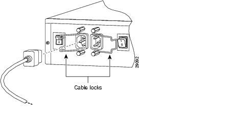
Figure 4-13 Connecting the One-to-One Cable to the Cisco RPS

Step 4 On the Cisco RPS rear panel, connect an AC power cable to either or both of the power connectors. Use the cable locks on the Cisco RPS to lock the cables in place. (See Figure 4-14.)

Figure 4-14 Connecting the AC Power Cables to the Cisco RPS

Step 5 Connect the other end of the Cisco RPS AC power cable into an AC power outlet.

Step 6 If you are using the redundant-with-reboot configuration (not recommended), power up the switch by connecting the switch AC power cord into an AC power outlet.


Note If you use the redundant-with-reboot configuration, always power up the switch before you power up the Cisco RPS.


Step 7 Power up the Cisco RPS. There is one power switch for each of the AC input power modules. Make sure that the power switch for each connected AC cable is in the ON (|) position. (See Figure 4-15.)

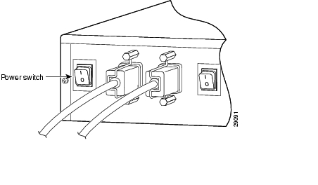
Figure 4-15 Powering Up the Cisco RPS

The Cisco RPS provides power in 10 to 15 seconds. The Cisco RPS is working properly when all its front panel LEDs are solid green. If the external device does not power up, refer to "Troubleshooting the Cisco RPS."


Note If you are using a Cisco RPS with a revision level lower than Z3 with a Catalyst 3508G or a Catalyst 3548 XL switch, the switch RPS LED and the RPS DC LED might display amber (normally indicating Cisco RPS malfunction) even when the Cisco RPS is functioning properly. The LEDs display correctly for Cisco RPS revision level Z3 or later revision. The label on the bottom of the Cisco RPS shows the revision level.


Connecting Routers and the Cisco MC3810 Concentrator

This section provides illustrations and cabling information for connecting the Cisco RPS to Cisco 2500 series and Cisco 2600 series routers; Cisco 3620, Cisco 3640, and Cisco 3725 routers; Cisco 4000 series routers and Cisco MC3810 multiservice concentrators. All these devices use:

One-to-one cable for quasi-redundancy

or

Two-to-one Y-cable for full redundancy


Note If you did not order your router or concentrator with a Cisco RPS connector installed, you must order a power adapter plate and must install it in place of your existing power supply.

If you need to order a power adapter plate, see Table 3-1, which lists adapter plates and corresponding product order numbers. Contact Cisco Customer Service at 800 553-6387 or 408 526-7209 for ordering information. (See also the "Obtaining Documentation" section on page xviii.)

Device-specific instructions for installing the Cisco RPS adapter plate are shipped with the plate and are also available on Cisco.com at  http://www.cisco.com.


Note Cisco IOS Software Release 11.2(7)P or later release is required when using the Cisco RPS with Cisco 3620, Cisco 3640, or Cisco 3725 routers.


To connect a router or multiservice concentrator to the Cisco RPS, perform the following steps:


Step 1 Power off the router or concentrator by pressing the power switch to the OFF (O) position.

Step 2 Connect one end of the one-to-one cable or Y-cable to the Cisco RPS connector on the rear panel of the router or concentrator, as shown in Figure 4-16 through Figure 4-21.

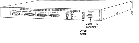
Figure 4-16 Cisco 2500 Series Router Rear Panel

Figure 4-17 Cisco 2600 Series Router Rear Panel

Figure 4-18 Cisco 3620 Router Rear Panel

Figure 4-19 Cisco 3640 Router Rear Panel

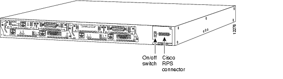
Figure 4-20 Cisco 4000 Series Router Rear Panel

Figure 4-21 Cisco MC3810 Multiservice Concentrator Rear Panel

Step 3 Connect the other end of the one-to-one or Y-cable to the rear panel connector on the Cisco RPS, as shown in Figure 4-22 and Figure 4-23.

Figure 4-22 Connecting a One-to-One Cable for Quasi-Redundant Power

Figure 4-23 Connecting a Two-to-One Y-Cable for Fully Redundant Power

Step 4 On the rear panel of the Cisco RPS, connect an AC power cable to either or both of the power connectors. Use the cable locks on the Cisco RPS to lock the cables in place. (See Figure 4-24.)

Figure 4-24 Connecting the AC Power Cables to the Cisco RPS

Step 5 Connect the other end of the Cisco RPS AC power cable into a grounded AC power outlet.

Step 6 Power up the Cisco RPS. There is one power switch for each of the AC input power modules. Make sure that the power switch for each connected AC cable is in the ON (|) position. (See Figure 4-25.)

Figure 4-25 Powering Up the Cisco RPS

Step 7 Power on the router or concentrator by pressing the power switch to the ON (|) position.

The Cisco RPS is on and provides power to the external device in 10 to 15 seconds. The Cisco RPS is working properly when all its front-panel LEDs are solid green. If the external device does not power up, see "Troubleshooting the Cisco RPS."


hometocprevnextglossaryfeedbacksearchhelp

Posted: Fri Nov 9 11:04:57 PST 2007
All contents are Copyright © 1992--2007 Cisco Systems, Inc. All rights reserved.
Important Notices and Privacy Statement.