|
|

This chapter describes the use of Multichassis Multilink Point-to-Point Protocol (MMP) on the Cisco AccessPath Integrated Access System. The chapter begins with the principles of MMP and how it works and then includes procedures for configuring MMP.
To enable MMP on the AccessPath system, you must configure both the Access Server Shelves and the Router Shelves. This chapter begins with a general discussion of and cont.
Topics in this section include the following:
This section presents a brief overview of MMP operations and includes the following topics:
MMP is a new feature in Cisco IOS Release 11.2 that extends Multilink PPP Protocol (MP, also known as MLP) functionality across multiple chassis.
MP gives users additional bandwidth on demand by splitting and recombining packets across a logical pipe (bundle) formed by multiple links. On the transmit end, MP provides for the fragmentation of a single packet into multiple packets for transmission across multiple PPP links. On the receive end, MP provides packet reassembly from multiple PPP links.
MMP enhances MP by permitting MP links from a single client to terminate on different access servers. The whole process is invisible to the user.
MMP allows Internet Service Providers (ISPs) and Enterprise system administrators the flexibility to group multiple access servers into a single rotary group that users can access from a single number. The MMP client is unaware that the MP bundle is made up of links terminating on different access servers.
MMP is particularly suited to the Cisco AccessPath Integrated Access System for the following reasons:
MMP works with the Stack Group Bidding Protocol (SGBP), which supports bidding and arbitration across multiple shelves in the AccessPath system. When you have a higher-powered CPU available as a stack member relative to the other stack members, you can leverage the more powerful CPU of that stack. The designated stack member can be configured as the offload server with the command sgbp seed-bid offload.
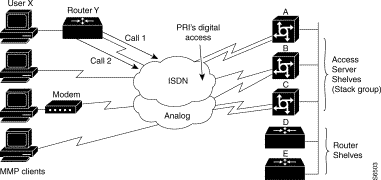
In the AccessPath system, this is how the Router Shelves are designated as the offload servers and made to host the master bundle for MMP calls. All MP calls from the Access Server Shelves are offloaded to the Router Shelves. See Figure 5-1.
In Figure 5-1, User X (connected to Router Y) takes advantage of the added bandwidth provided by MP when dialing into the AccessPath system stack. The following sequence illustrates a typical scenario when the AccessPath system is configured to offload MP traffic to the Router Shelf:
1. Call 1 is made and Access Server Shelf A accepts the call.
2. Access Server Shelf A informs its peers that it has accepted a call from User X.
3. All peers of Access Server Shelf A bid for ownership of the call.
4. Because the AccessPath system is configured for sgbp seed-bid offload, one of the Router Shelves (D and E in the illustration) always wins the bid and becomes the bundle master for this MP session.
5. When User X needs more bandwidth, Call 2 is made and, in this example Access Server Shelf C accepts the call and informs the stack group
6. The stack group members bid for ownership of the call, but Router Shelf D wins the bid because it already has an MP session with User X.
7. Access Server Shelf A sets up an L2F tunnel to pass raw PPP data between the Access Server Shelf that answered the call and the Router Shelf that won the bid for the call.
To enable MMP and terminate all MP calls in an Router Shelf, in global configuration mode configure the Access Server Shelves as follows:
In the following example, "stack" is defined as the user name, and "stackpass" is set as the password.
Step 2 Define a named stack group and make the system a member of that stack group. The stack group name must be unique within a domain. You cannot define multiple stack groups on the AccessPath system. In the following example, the stack group name is defined as "stack," and the Access Server Shelf is made a member.
Step 3 Specify the case-sensitive host name and IP address of the Router Shelf (or Shelves). In the following example, "offload01" with IP address 192.168.23.45 is defined as a member of the stack group.
Note All Access Server Shelves must list all Router Shelves, but they need not list other Access Server Shelves.
Repeat Step 3 for other Router Shelves in the stack group.
Step 4 Use the sgbp seed-bid command to configure the weight that the stack member will use when bidding to be a bundle master. In the following example, all Access Server Shelves will always be configured as "forward-only."
Step 6 Repeat Step 1 through Step 5 for each Access Server Shelf in the stack.
To enable MMP and define the Router Shelves as offload processors, in global configuration mode configure each Router Shelf as follows:
Step 2 Define a named stack group and make the system a member of that stack group. The stack group name must be unique within a domain. You cannot define multiple stack groups on the AccessPath system.
In the following example, the stack group name is defined as "stack," and the Router Shelf is made a member.
Step 3 Specify the case-sensitive host name and IP address of all Access Server Shelves in the stack group. It is also necessary to list the other Router Shelf (if you have a dual Router Shelf configuration).
In the following example, "nas01" with IP address 192.168.2.5 is defined as a member of the stack group.
Repeat Step 3 for all members of the stack group.
Step 4 Use the sgbp seed-bid command to set the Router Shelf to be used when bidding to be a bundle master.
In the following example, offload01 is defined as an offload processor.
Step 5 Enable PPP multilink for Virtual template 1.
Step 6 Define a virtual template interface. A virtual template interface is used to provide the configuration for dynamically created Virtual-Access interfaces.
The following example defines virtual template 1.
Step 8 Repeat Step 1 through Step 7 for each Router Shelf in the stack.
Note The virtual template interface serves as a template by which any number of virtual access interfaces are cloned dynamically. You should not specify per-interface protocol-specific addresses to the virtual template interface.
![]()
![]()
![]()
![]()
![]()
![]()
![]()
![]()
Posted: Tue Jan 21 03:21:35 PST 2003
All contents are Copyright © 1992--2002 Cisco Systems, Inc. All rights reserved.
Important Notices and Privacy Statement.