|
|

This chapter provides the following information about unpacking and installing your Cisco Micro Hub:
 Timesaver You can also use the quick reference card that came with your hub for quick instructions on how to install and configure your hub.
To ensure personal safety and protect the equipment, follow these guidelines:
 Caution Do not place anything on top of the hub that could block the air flow from the vents on top of the hub. Products designed specifically to interoperate with the hub and which are stacked on top of the hub with the included stacking clip will not block the air flow from the vents.
 Warning Read the installation instructions before you connect the system to its power source.
 Warning Before working on equipment that is connected to power lines, remove jewelry (including rings, necklaces, and watches). Metal objects heat up when connected to power and ground and can cause serious burns or weld the metal object to the terminals.
 Warning Before working on a system that has an on/off switch, turn OFF the power and unplug the power cord.
 Warning Ultimate disposal of this product should be handled according to all national laws and regulations.
 Warning The power supply is designed to work with TN power systems.
 Warning Do not work on the system or connect or disconnect cables during periods of lightening activity.
 Warning The ports labeled "1X" through "8X," "CONSOLE," "OUT," and "IN" are safety extra-low voltage (SELV) circuits. SELV circuits should only be connected to other SELV circuits. Avoid connecting these circuits to telephone network voltage (TNV) circuits.
Make sure that you receive all the items shown below.
There are five major steps for installing the hub:
1 ) Stacking Hubs (if you are using more than one hub)
2 ) Connecting Hubs (if you are using more than one hub)
3 ) Connecting the Power and Turning the Hub On
4 ) Connecting Other Network Devices to the Hub
5 ) Connecting the CONSOLE Port (Micro Hub 1503 only)
 Timesaver If you are using only one hub, skip the next two sections, and go directly to the section "Connecting the Power and Turning the Hub On."
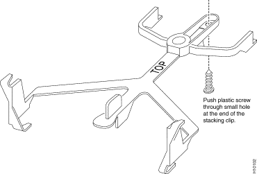
Up to four Cisco Micro Hubs can be stacked on top of one another and connected using ports on the rear panel. Each hub comes with a stacking clip and a screw that are used to keep multiple hubs together in a stack.
Before using the clip, you must assemble the clip and the screw, as shown below.
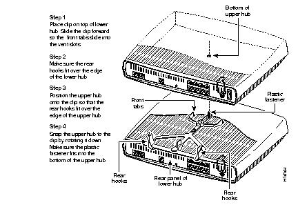
After pushing the screw into the stacking clip, use the clip as shown below.
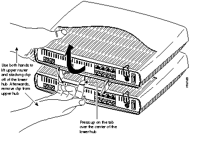
To separate hubs that are connected with the stacking clip, follow the instructions below:
This section describes the two ways that the hubs can be connected to each other.
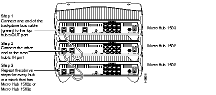
If the stack contains only Micro Hub 1503s and Micro Hub 1502s, connect the hubs as shown below.
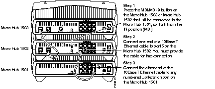
If the stack contains a Micro Hub 1501, connect it as shown below.
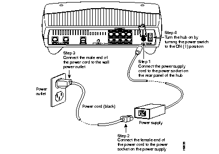
Connect power and turn the hub on as shown in the following illustration. (Do this for each hub in a stack of hubs.)
 Warning This product relies on the building's installation for short-circuit (overcurrent) protection. Ensure that a fuse or circuit breaker no larger than 120 VAC, 15A U.S. (240 VAC, 10A international) is used on the phase conductors (all current-carrying conductors).
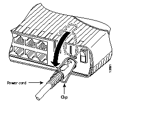
To prevent the power cord from disconnecting from the hub, slip the power-cord clip down over the power cord, as shown in the following illustration.
After turning the hub on, check the hub's front panel to make sure that certain LEDs are on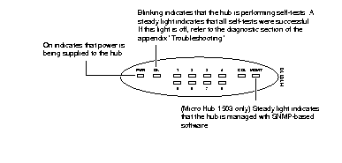
.
There are two types of devices that you can connect to the hub's workstation ports, labeled 1 through 8:
This section describes how to connect these devices to the hub.
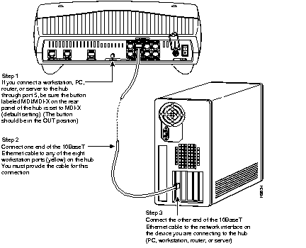
Connect network devices such as a workstations, PCs, routers, or servers to the ports on the hub labeled 1 through 8, as shown in the following illustration. The network device must have a 10BaseT network interface in order for it to be connected to the hub.
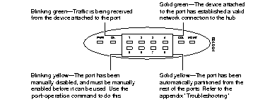
After connecting a network device to the hub, check the corresponding port LED (labeled 1 through 8) on the front panel. The color and blinking pattern of the LED indicate the activity for the corresponding workstation port.
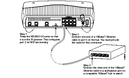
Connect compatible 10BaseT hubs or switches to the Cisco Micro Hub through port 5, as shown in the following illustration.
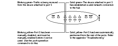
After connecting a hub or switch to port 5, check the LED labeled 5 on the front panel. The color and blinking pattern of the LED indicate activity for port 5.
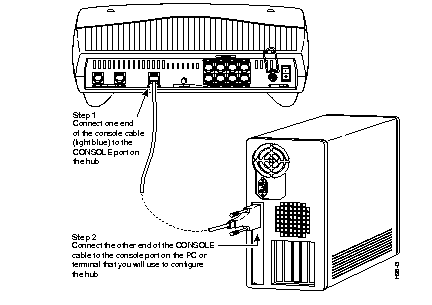
This section applies only to the Micro Hub 1503; the Micro Hub 1502 and the Micro Hub 1501 do not have a CONSOLE port.
Connect the Micro Hub 1503's CONSOLE port to a PC, as shown below, or to a terminal, so that you can control and monitor the hub using network management software or using terminal emulation software.
The terminal or terminal emulation software should be configured with the following settings: 9600 baud, 8 data bits, 1 stop bit, no parity, and no flow control.
You have now completed the basic hardware installation of the hub. To configure the hub, go to the next chapter, "Using Your Hub Software."
|
|