294
Chapter 7
Multi-Layer Switching (MLS)
Hands-On Lab
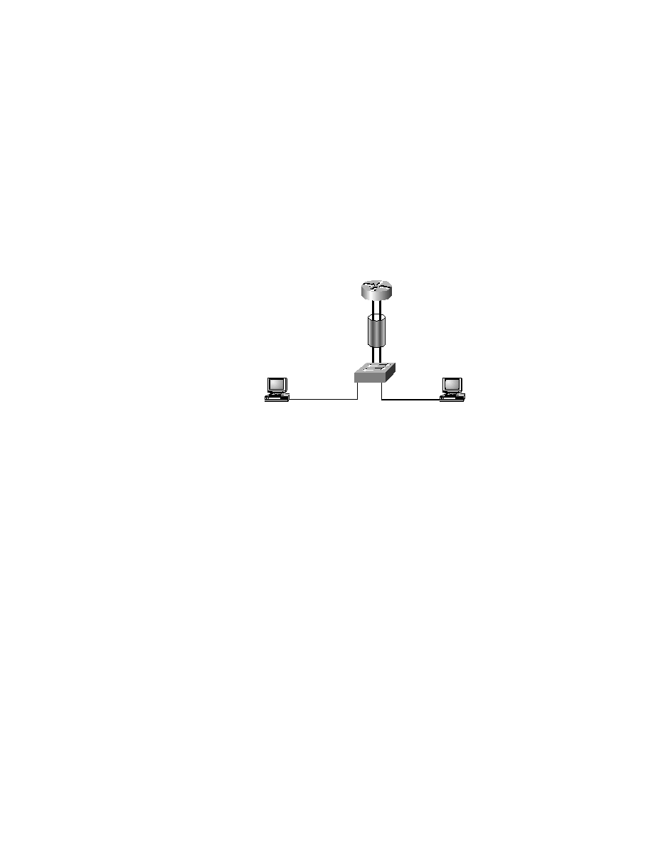
Refer to Figure 7.10 for the topology of this lab. This lab will use the
simplest architecture: router on a stick using a Catalyst 5000 and an external
router (7200 series).
F I G U R E 7 . 1 0
Lab topology
1.
Assume that RouterA does not have MLS enabled. You may assume
that the subinterfaces are running ISL and have VLAN assignments.
Switch1 is a VTP server for the sybex domain. Configure MLS to work
on RouterA.
Answer:
RouterA#conf t
Enter configuration commands, one per line. End with
CNTL/Z.
VLAN10
VLAN50
FE0/0.10
FE0/0.50
FE0/0
RouterA
Switch1
HostA
HostD
Copyright ©2000 SYBEX , Inc., Alameda, CA
www.sybex.com