190
Chapter 5
Interconnecting OSPF Areas
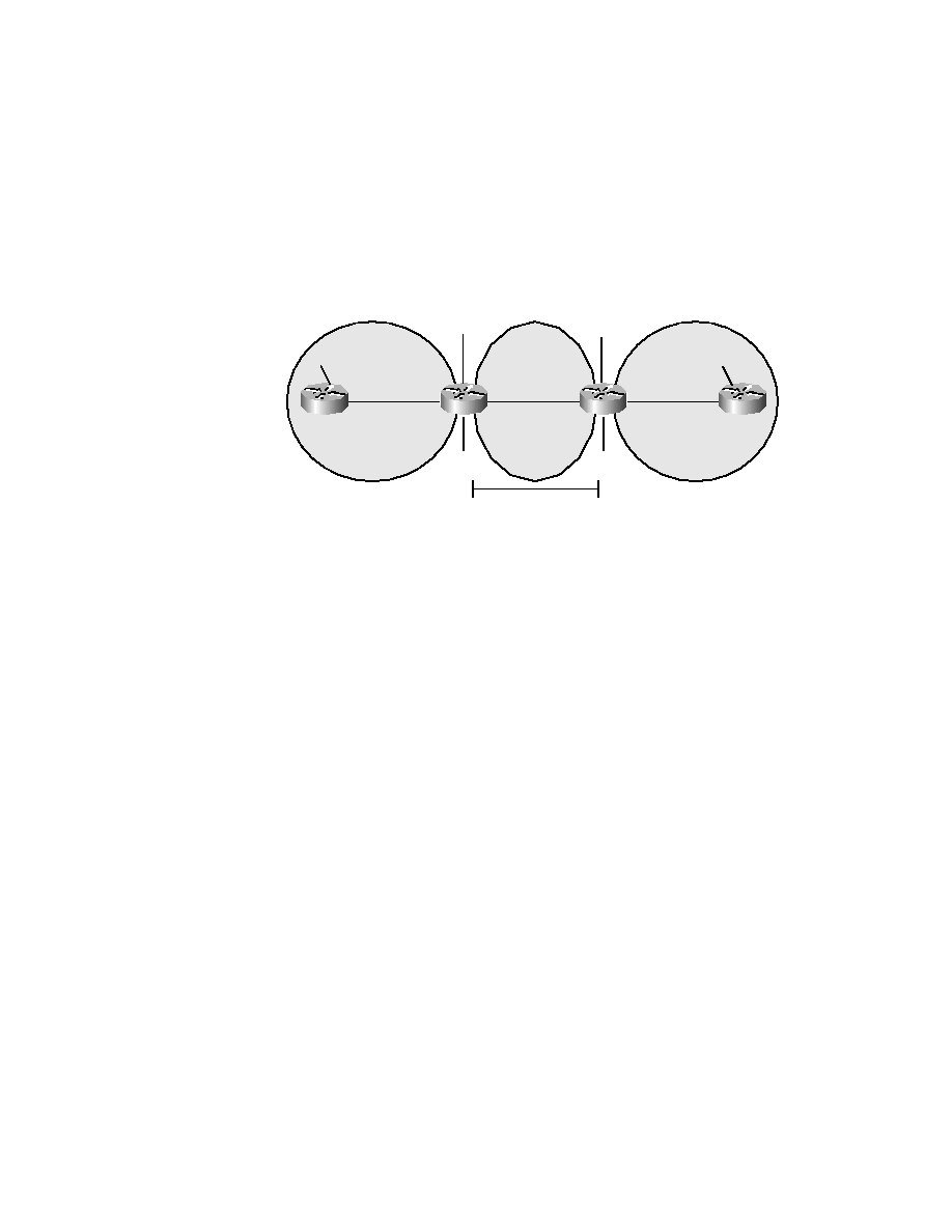
Since a virtual link requires that only the ABRs on each side of the transit
area be configured, we will examine only the configuration of RouterB and
RouterC.
As shown in the above graphic, RouterB uses the following command to
create its side of the virtual link:
area 2 virtual-link 6.6.6.6
where 2 is the transit area and where 6.6.6.6 is the Router ID (the highest
loopback IP address) of the ABR at the other side of the transit area.
Similarly, RouterC uses the following command to create its side of the
virtual link:
area 2 virtual-link 3.3.3.3
where 2 is the transit area and where 3.3.3.3 is the Router ID (the highest
loopback IP address) of the ABR at the other side of the transit area.
RouterB
interface Loopback0
ip address 3.3.3.3 255.255.255.0
!
internet Ethernet0
ip address 2.2.2.3 255.255.255.0
!
interface Ethernet1
ip address 4.4.4.4 255.255.255.0
!
router ospf 20
RouterA
RouterB
RouterC
RouterD
Lo0:6.6.6.6/24
Lo0:1.1.1.1/24
2.2.2.2/24
e0
e0
e1
e0
2.2.2.3/24
e1
e0
4.4.4.4/24
4.4.4.5/24
7.7.7.7/24
7.7.7.8/24
Area 0
Area 2
Area 1
Lo0:8.8.8.8/24
Lo0:3.3.3.3/24
Virtual Link
Copyright ©2001 SYBEX , Inc., Alameda, CA
www.sybex.com