184
Chapter 5
Interconnecting OSPF Areas
OSPF Virtual Links
W
hen designing a multi-area OSPF network, all areas should be con-
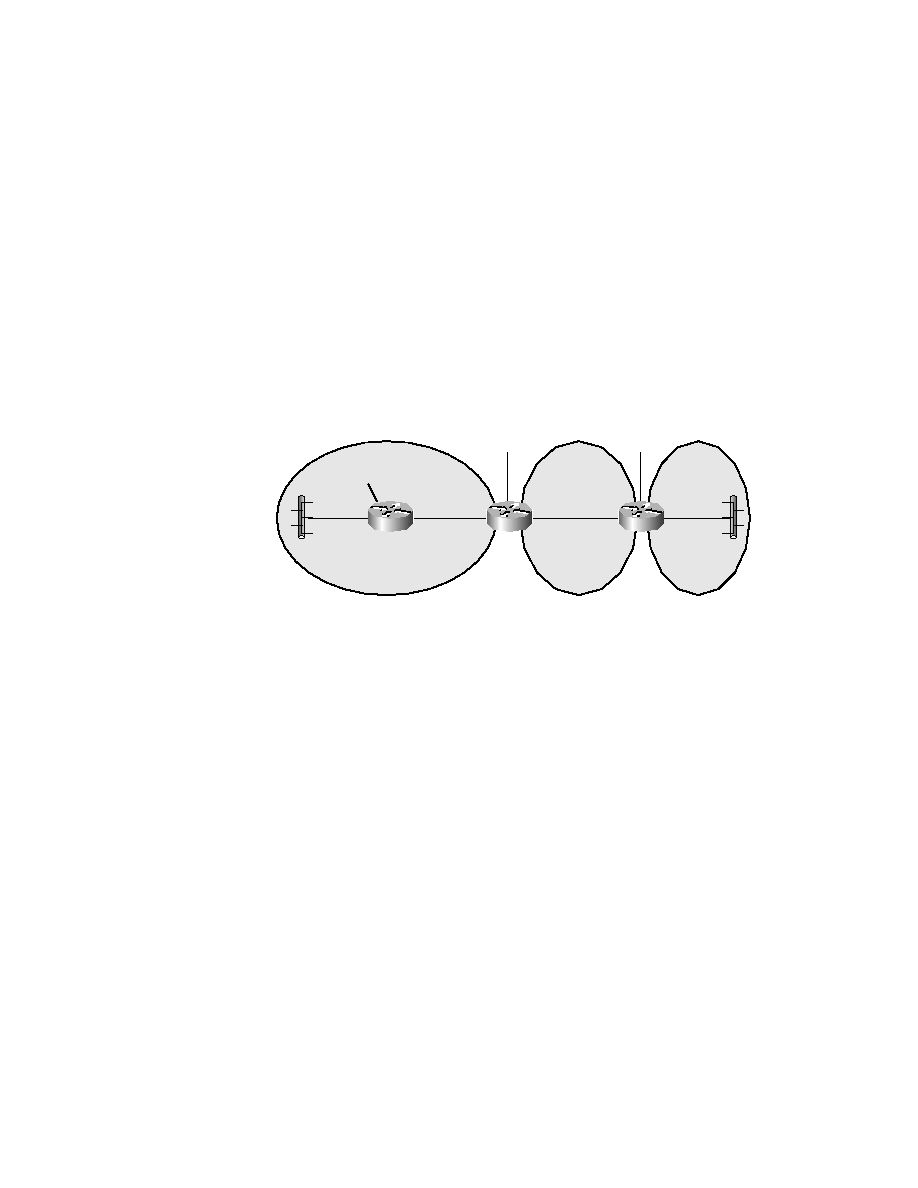
nected to the backbone area. However, there may be instances when an area
has to cross another area to reach the backbone area, as shown in Figure 5.7.
Since, in this example, Area 20 does not have a direct link to Area 0, we need
to create a virtual link.
F I G U R E 5 . 7
OSPF virtual link
The syntax for creating a virtual link across an area is
area
area-id virtual-link router-id
where area-id is the number of the transit area, in this example, Area 10,
and router-id is the IP address of the highest loopback interface configured
on a router. If a loopback interface has not been configured on the router,
then the router-id is the highest IP address configured on the router. Note
that a virtual link has area border routers as the endpoints of the link.
As shown in Figure 5.8, we are going to create a virtual link from Area 20
to Area 0, with Area 10 acting as the transit area. Let's examine the config-
uration of RouterB and RouterC, since RouterA does not have any virtual-
link-specific configuration.
RouterA
RouterB
RouterC
Ethernet
Ethernet
Lo0:2.2.2.1/24
1.1.1.1/24
e0
e1
e0
e1
3.3.3.1/24
e0
e1
3.3.3.2/24
4.4.4.1/24
4.4.4.2/24
7.7.7.1/24
Area 0
Area 10
Area 20
Lo0:6.6.6.1/24
Lo0:5.5.5.1/24
Copyright ©2001 SYBEX , Inc., Alameda, CA
www.sybex.com