284 Chapter 9: Frame Relay Connection Controlling Traffic Flow
Scenarios
The following case studies and questions are designed to draw together the content of the
chapter and exercise your understanding of the concepts. There is not necessarily a right answer
to each scenario. The thought process and practice in manipulating the related concepts is the
goal of this section.
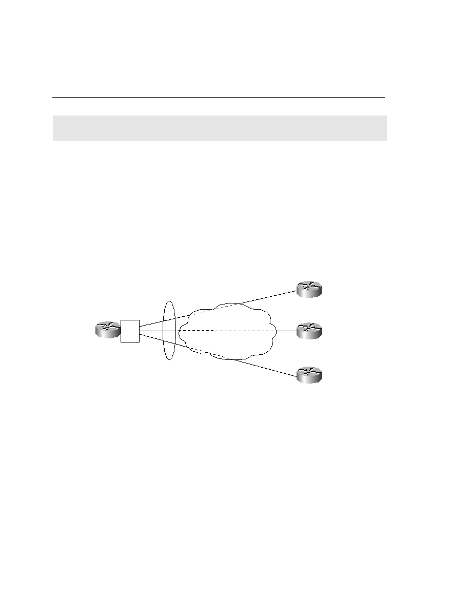
Scenario 9-1
Consider Figure 9-8 for purposes of this scenario. This is a new network deployment and care
must be taken to ensure that all routers have full reachability information available to them at
all times.
Figure 9-8
Scenario Topology
1
Configure Router A for basic Frame Relay connectivity. Use the addressing and DLCIs
noted in Figure 9-8. Assume the use of the default LMI type.
2
Configure Router B for basic Frame Relay connectivity.
3
Configure Router C for basic Frame Relay connectivity.
4
Configure Router D for basic Frame Relay connectivity.
S0.1
S0.2
S0.3
A
D
B
DLCI=112
DLCI=110
DLCI=111
Frame Relay
cloud
S0 IP=172.16.10.2/24
DLCI=40
S0 IP=172.16.20.2/24
DLCI=40
S0 IP=172.16.30.2/24
DLCI=40
S0.1 IP=172.16.10.1/24
S0.2 IP=172.16.20.1/24
S0.3 IP=172.16.30.1/24
CIR=128 kbps
CIR=64 kbps
CIR=256 kbps
C