disable LMI completely, use the no keepalive command to cease to transmit and receive LMI.
However, keepalives must also be disabled at the switch.
connections, mapping of protocol addresses to DLCIs is dynamic and requires no intervention
(usually). However, if point-to-multipoint connections are in use, manual mapping is necessary.
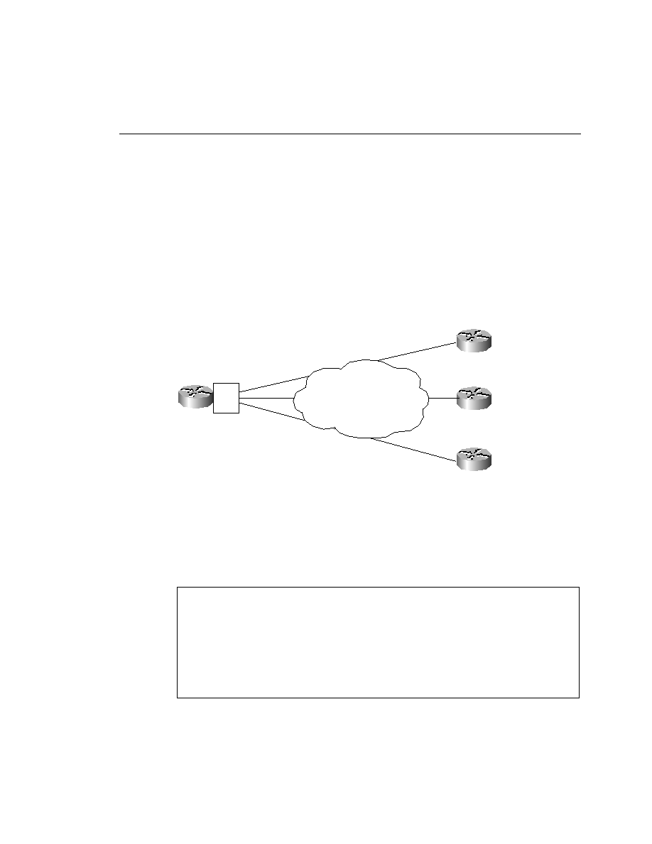
section of the chapter. Figure 9-7 depicts a sample topology.
subnets. The central router in this configuration is RouterA.
defined. In addition, because Example 9-1 already uses point-to-point interfaces, the only thing
lacking is the DLCI, which the configuration in Example 9-2 provides.
RouterA(config-if)#encapsulation frame-relay
RouterA(config-if)#interface serial 0.1 point-to-point
RouterA(config-subif)#ip address 10.1.1.1 255.255.255.0
RouterA(config-subif)#frame-relay interface-dlci 16
RouterA(config-fr-dlci)#interface serial 0.2 point-to-point
RouterA(config-subif)#ip address 10.1.2.1 255.255.255.0
RouterA(config-subif)#frame-relay interface-dlci 17
RouterA(config-fr-dlci)#interface serial 0.3 point-to-point
RouterA(config-subif)#ip address 10.1.3.1 255.255.255.0
RouterA(config-subif)#frame-relay interface-dlci 18
S0.2
S0.3
DLCI=20
DLCI=20
DLCI=20
S0.2 IP=10.1.2.1/24
S0.3 IP=10.1.3.1/24