Each has its own advantages and disadvantages, as pointed out in the following list:
deploying Frame Relay. It consists of a single central site acting as a connection point for
all remote offices. Routing between two satellite offices is accomplished through the
central site. Routing through the central site tends to be the low-cost solution; however, it
is also the least redundant (that is, fault tolerant) strategy.
has a large number of connections and is very expensive to operate; however, it is the most
fault tolerant. Because each site is connected to every other site, the number of
connections can be large and expensive. The number of connections that are required is
derived through the following formula, where n is the number of devices you wish to
connect: n(n 1)
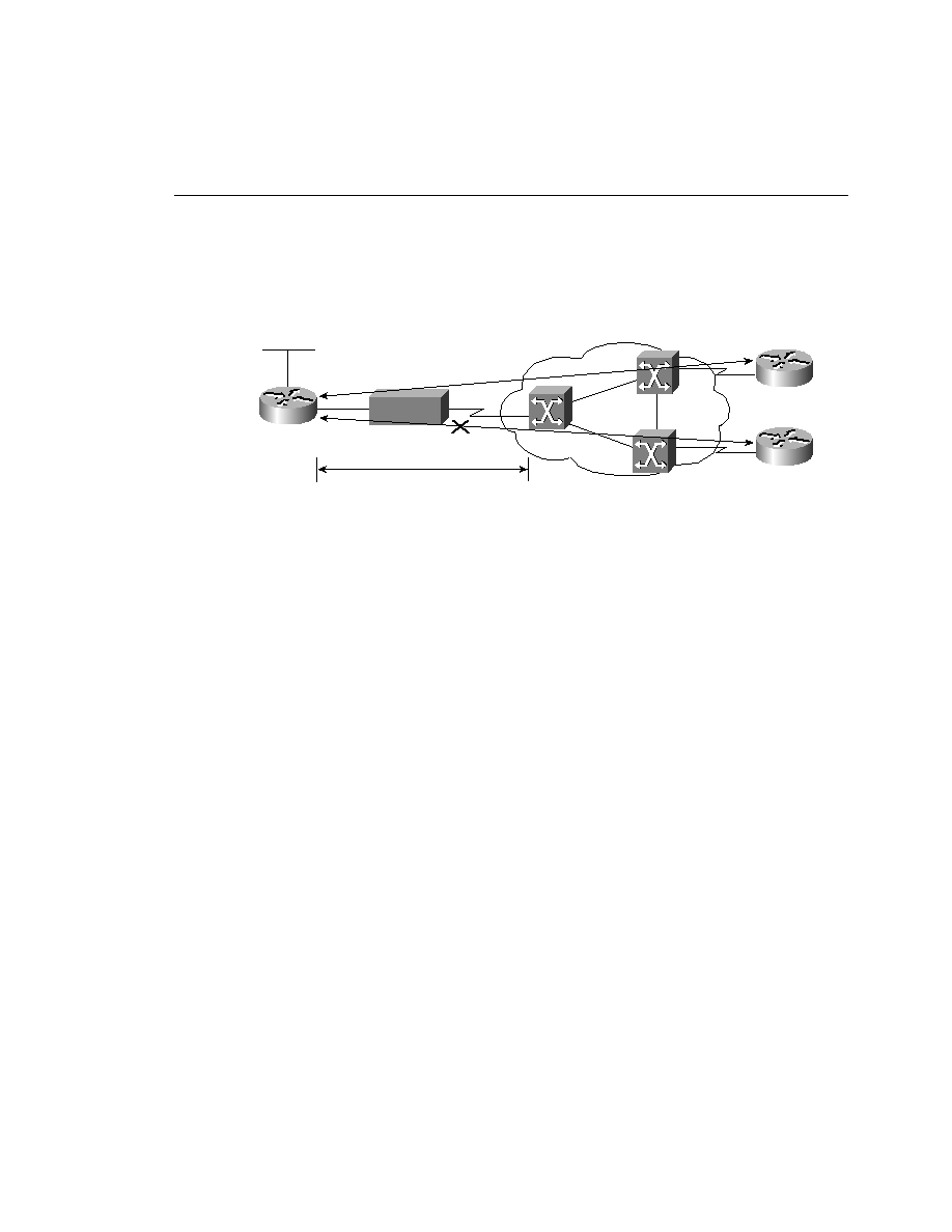
implementation, the cost of full mesh is avoided, and the lack of fault tolerance of hub and
spoke is minimized. Although a central site is utilized, redundant connections are installed
between critical sites. In essence, it is possible to create a backup central site. This is
particularly useful in networks in which delay reductions are necessary because getting to
a destination without traversing a central router can decrease delay significantly.
16=Active
18=Inactive