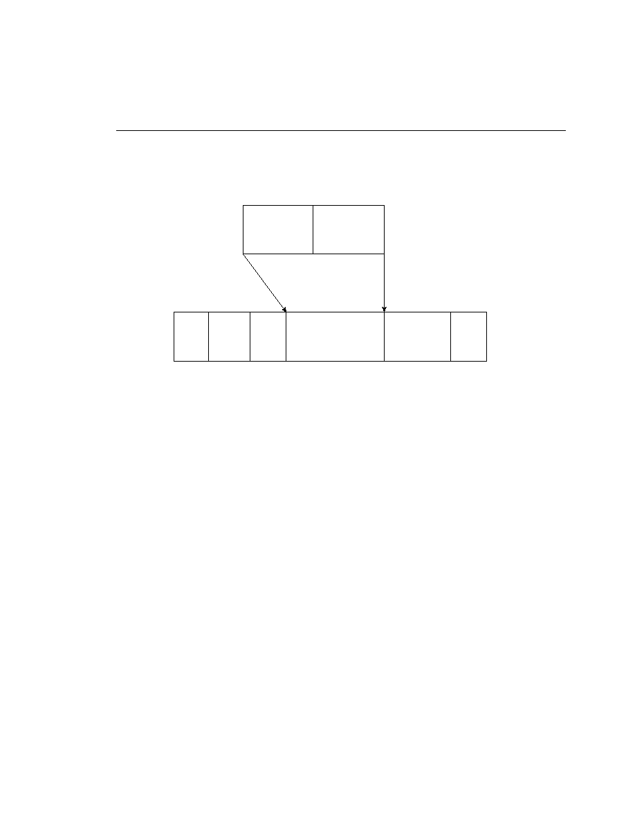
the frame structure. The user data is simply encapsulated into an X.25 packet, which is placed
into the LAPB frame for transport through the physical layer.
technology, so it is obviously implemented on serial interfaces at varying speeds. Physical
implementation of any serial-based technology requires the use of a transition cable purchased
separately from the router. The cable must be specific to the type of serial interface installed in
the router (EIA/TIA-232, V.35, and so on) as well as the type of interface on the CSU/DSU
(DB-25, Winchester Block, and so on). Once the physical cabling is in place, the serial interface
can be configured appropriately.
involves the gathering of information that is needed to properly initialize the X.25 interface and
enable communication. The following tasks are necessary:
no specification is made, the setting defaults to DTE.
provider.