186 Chapter 6: Using ISDN and DDR Technologies
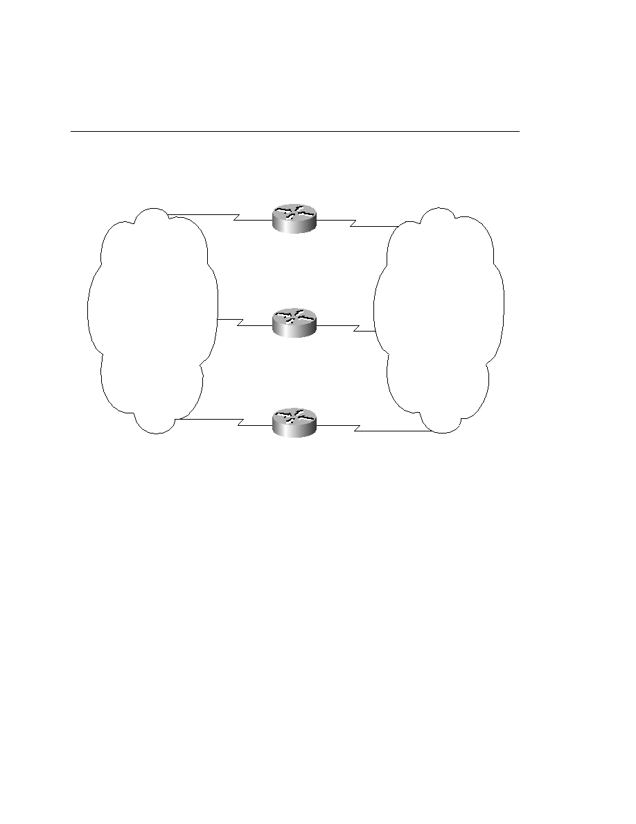
Figure 6-19
Expanded Network Topology
1
Configure dial backup on all three routers to provide redundancy five seconds after a
failure until sixty seconds after the failure has cleared.
2
Configure dial backup on all three routers to provide load balancing in the event that the
load on the Frame Relay circuit reaches 90 percent. The link should stay active until the
aggregate load is reduced to 10 percent.
Scenario 6-4
In the course of testing the configuration of dial backup in Scenario 6-3, you found that the
ISDN circuits are not functioning properly.
1
Plan and document your Layer 1 troubleshooting strategy.
2
Plan your Layer 2 troubleshooting strategy. Document the show and debug commands
used at this point.
3
You've found that you are not receiving a TEI from the switch. Layer 1 is down. What are
the possible causes?
4
Plan your Layer 3 troubleshooting strategy. Document the show and debug commands
used at this point.
Atlanta
Raleigh
San Francisco
S0
10.1.210.2/24
BRI0
10.1.210.3/24
BRI0
10.1.210.1/24
Dialer 2
10.31.10.2/24
DLCI 80
10.31.20.2/24
DLCI 50
10.31.20.1/24
DLCI 17
S0
S0.1
10.31.10.1/24
DLCI 16
S0.2
Frame
Relay
ISDN