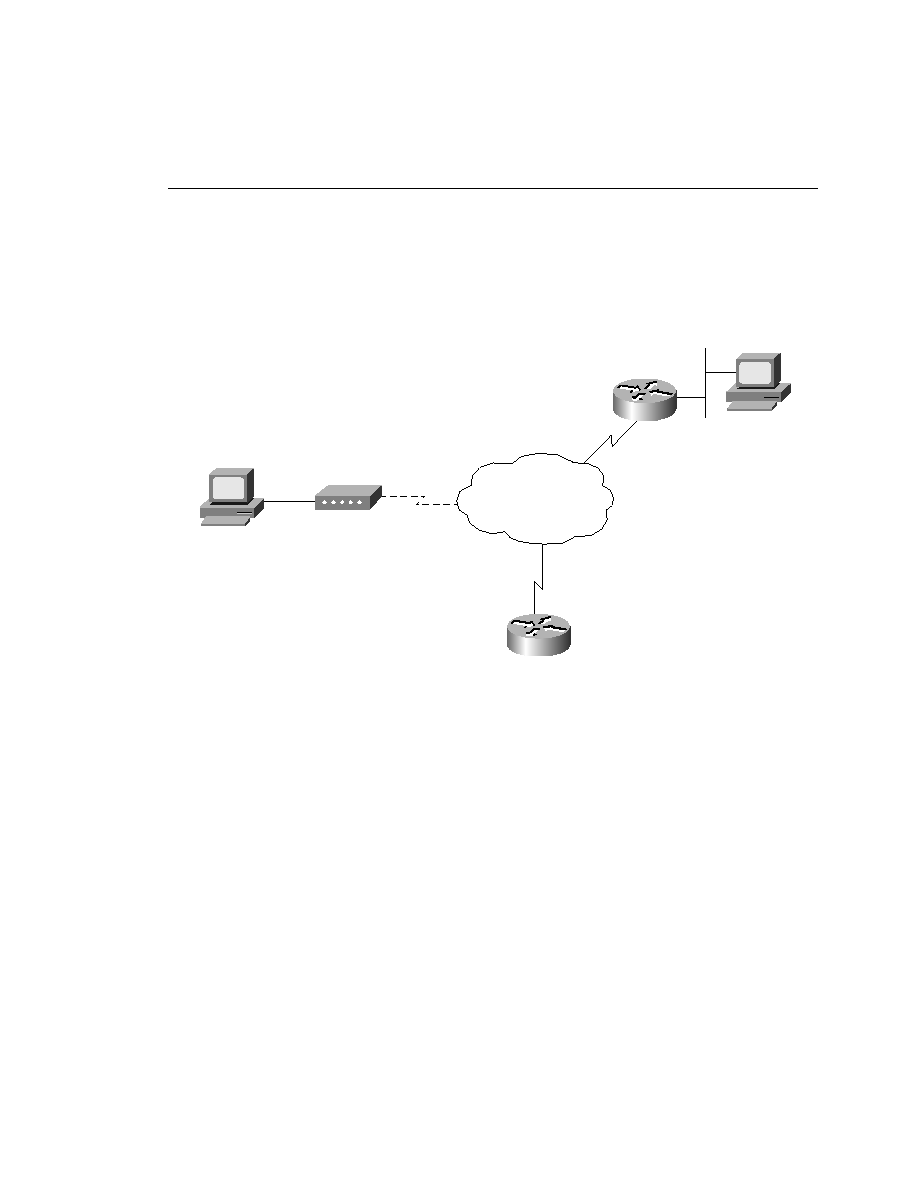
provide connectivity from end user to the access server are PRI implementations. These PRI
lines are completely digital facilities. Figure 6-16 illustrates the typical deployment of an access
server installation.
inbound from a modem. In other words, it sees the call as an incoming analog call. If it were a
call from another B channel, the call would be completely digital; however, because the call
originated from an analog modem, the NAS must answer back in the form expected by the
modem. Using the isdn incoming-voice modem command, the router passes the call off to one
of the internal MICA modems installed in the NAS.
the PC and the modem. The modem converts the transmission to analog (that is, modulated) and
passes it off to the edge CO switch. Once inside the PSTN, the transmission is again converted
to digital format for its journey across the PSTN. Once the transmission arrives at the remote
edge switch, it is converted back to analog only to be changed back to digital by the modem
(that is, demodulated) at the remote site and forwarded to the receiving party. It all seems a bit
redundant.
up to the point where the call is demodulated by the remote modem. In a NAS implementation,
the demodulation is not necessary. It is taken, in digital form, and passed to a MICA modem