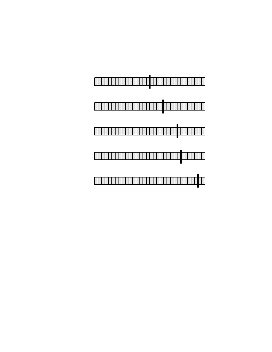
specifies the number of bits (beginning from the left) that define the network
portion. In this figure, the address 172.16.20.0/24 is equivalent to a Class
C address, however it is a Class B address with a /24 mask. You can tell that
because the first 24 bits are used to define the network portion, leaving 256
host addresses available. The first 24 binary bits are equal to the first three
octets in the dotted decimal format of an IP address.
octet. This allowed for only 254 IP networks. To resolve this dilemma, RFC
791 was defined and written. This RFC converted a previously classless IP
address structure into specific classes--five classes, to be exact. The three
most common ones are Classes A, B, and C. Prefix lengths were defined as
eight bits, 16 bits, and 24 bits, corresponding to Classes A, B, and C, respec-
tively. The first three bits in the first octet were used to determine the IP
address class. Table 2.3 shows how the classes were defined.