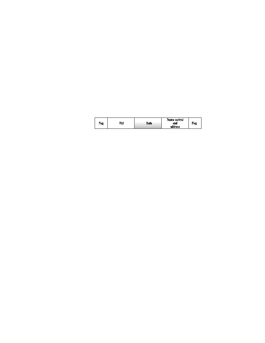
little deeper into X.25 by looking at the frame structure. Refer to Figure 2.34
for the graphical representation of the X.25 frame. X.25 frames are very sim-
ilar to SDLC frames. Each end is bounded with a Flag field. Starting from
the right and moving to the left, we start with a Flag segment. After the Flag
field, the frame contains the frame field control and address field.
ends with the FCS and Flag fields. The Layer 2 frame is simply a LAPB
frame.
developed as a digital packet-switching technology, whereas X.25 was an
analog technology. The technology used in Frame Relay allows it to multi-
plex several different data flows over the same physical media.
ers that allow the Frame Relay to keep track of each logical data flow. The
identifier is known as a DLCI (data link connection identifier). The DLCI
number is used to create a logical circuit within a physical circuit. Multiple
logical circuits can be created within one physical circuit. Look at the fol-
lowing router-configuration excerpt: