Relay interfaces, which helps with this issue, but you need different network numbers for each
subinterface, creating larger routing tables.
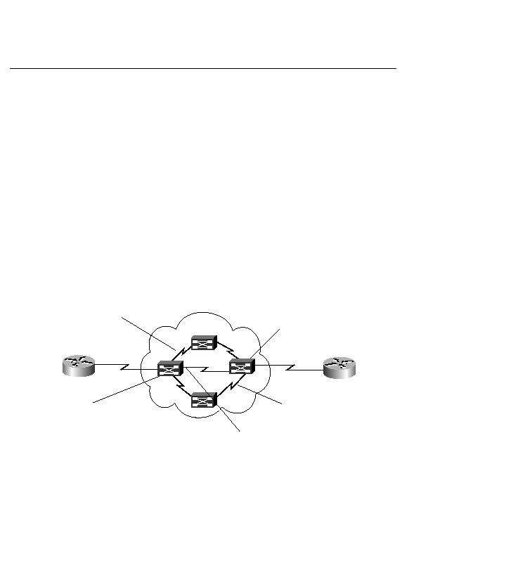
shows this process. You send out a frame with a Frame Relay header on it from Router A. Inside
that header is a DLCI number 100. There is no source or destination address, just the number
100. Think of a virtual circuit as pipes going through the Frame Relay carrier's cloud. Out of
the cloud comes the circuit with a frame with 200 in the header that traverses to Router B. In
the middle of the cloud, there could be many Frame Relay switches connecting the circuit from
end to end. The end-station routers know about only their "local" DLCI, not about any of the
others that might be involved in the connection. Because Frame Relay uses only this DLCI
address, it cannot reroute around failures like X.25 can. Frame Relay must depend on IP to
reroute around failures.
saying if it comes in Port A carrying the number 100, put it out Port B, which is how the
connection is made between the DLCIs.
each side. That is because 015 are reserved on the low end, and 10081023 are reserved on the
high end.