the window size is not end-to-end but rather only between the router and the local X.25 switch.
This window size negotiation happens on both sides of the cloud independently in this example.
Flow control is also implemented locally, or between the router and the local X.25 switch. Flow
control and window size negotiation also occur between the X.25 switches in the cloud via the
X.75 protocol.
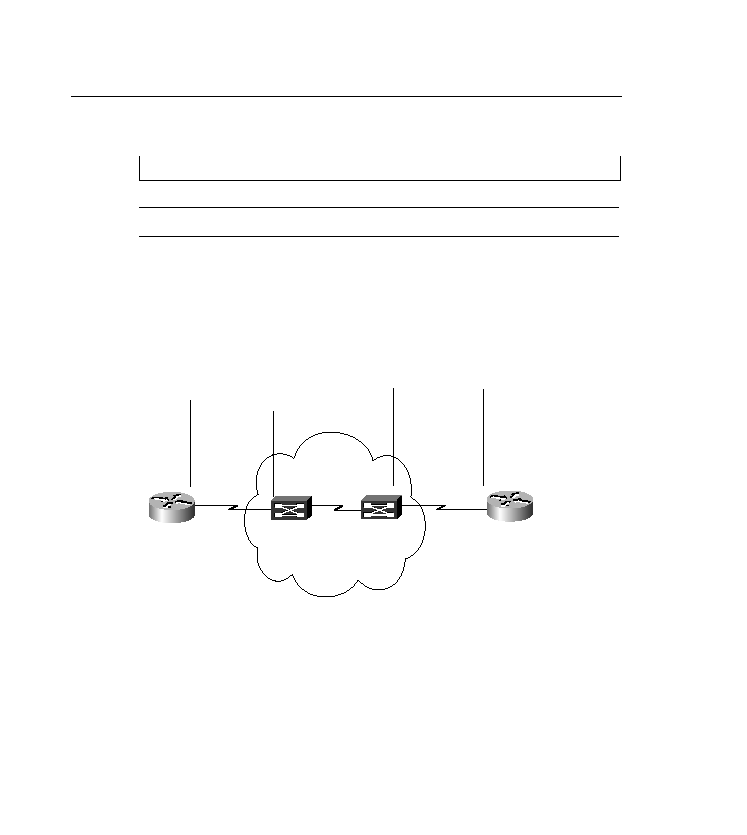
across the network, as shown in Figure 10-5. Notice that the two X.25 switches communicate
via the X.75 protocol. (Cisco does not support the X.75 protocol.)
carrier might actually encapsulate the X.25 packets into IP, a technique known as XOT (X.25
over TCP/IP [RFC 1613, first available in Cisco IOS version 9.21]), as shown in Figure 10-6.
In this example, X.25 packets are being encapsulated into TCP/IP by the routers. The IP
network is transparent to the X.25 devices.
12. x25 map ip 192.168.100.1 1111