334 Chapter 10: X.25/Frame Relay Topologies
Figure 10-3
X.25 Encapsulation
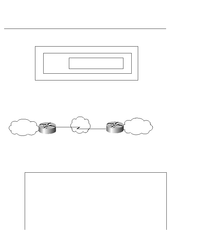
Datagram transport occurs between two hosts communicating over an X.25 network, as shown
in Figure 10-4. You configure datagram transport by establishing a mapping on the
encapsulating interface between IP and the X.121 address. (To avoid confusion, an X.121
address is applied with the command x25 address, not x.121 address.)
Figure 10-4
X.25 Configuration
In Example 10-1, line 3 specifies a DCE interface. This indicates that the clock is being
provided by this interface. One side of an X.25 connection must be a DCE, and the other side
a DTE.
Example 10-1
X25 Connection
Router Left
1. interface Serial0
2. ip address 192.168.100.1 255.255.255.0
3. encapsulation x25 dce
------"Logical" DCE
4. x25 address 1111
------- This router's "x121" adress
5. x25 map ip 192.168.100.2 2222
-Mapping the remote x121 address with the
remote IP address
6. clock rate 2000000
---Specifies clock rate 2000000 (The maximum
for X.25)
7. x25 route 2222 interface Serial 0
---Maps the remote x25 address to the serial
port
Router Right
8. interface Serial0
9. ip address 192.168.100.2 255.255.255.0
10. encapsulation x25
Data-link frame LAPB
X.25 header
IP datagram
X.25 cloud
IP cloud
IP cloud
Router left
Router right
S0
192.168.100.1
x 25 address 1111
S0
192.168.100.2
x 25 address 2222
87200333.book Page 334 Wednesday, August 22, 2001 2:53 PM