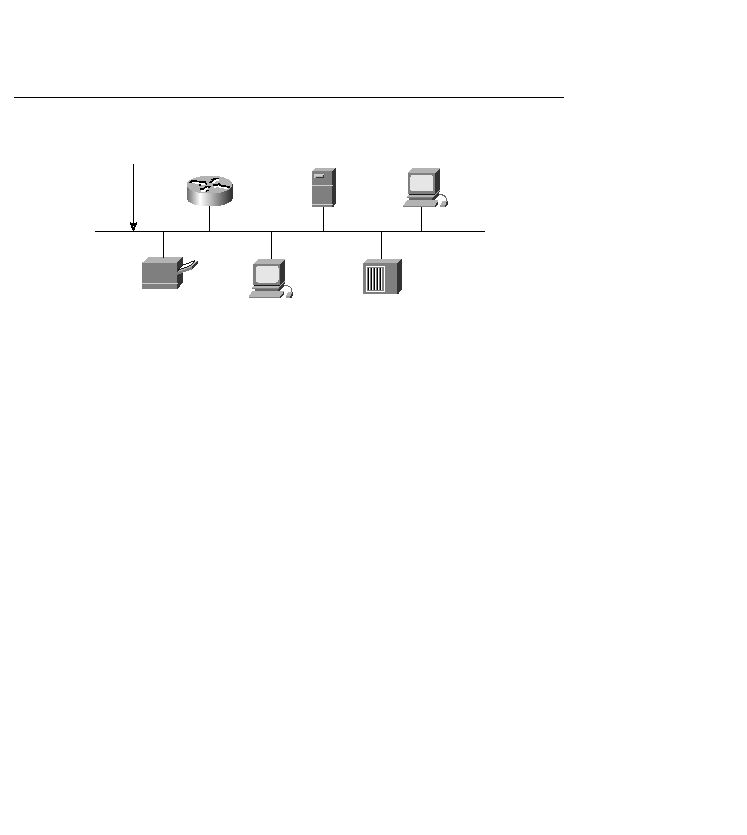
central controller. All stations attached to an Ethernet are connected to a logical bus topology.
Every packet travels the length of the bus and is seen by every other device on the bus. To send
data, a station first listens to the channel. If the channel is idle, the station transmits its data in
the form of an Ethernet frame.
frame transmission chance. This ensures that access to the network channel is fair, and that no
single station can lock out the other stations. Access to the shared channel is based on a system
called Carrier Sense Multiple Access with Collision Detection (CSMA/CD). As traffic
increases on the bus, the rate of collisions also increases. An excessive number of collisions
reduces the available bandwidth. Ethernet is designed so that a normal collision does not result
in lost data. In the event of a collision, the Ethernet interface waits for a period of time and then
automatically retransmits the data.
the wise CCDP knows that too much of anything can be a bad thing. An excessive number of
collisions reduces available bandwidth. If a design could be implemented using Ethernet that
bypasses the potential for a large number of collisions, Ethernet could represent the ideal
solution for a campus LAN environment. Ethernet switches provide the solution to the
bandwidth/collision problem.
several standards for Ethernet topologies: