| Previous | Table of Contents | Next |
Given the critical function of the DHCP server, most designers place at least two of them in a network, thus providing DHCP server redundancy. This design offers benefits similar to the redundant WINS servers discussed previously in this chapter. Depending on the implementation, these DHCP servers may or may not be able to share address assignment information. Multiple helper addresses may be placed on each interface on a Cisco router.
Many designers break the DHCP scope when working with DHCP servers that are not capable of automatic redundancy. Recall from the discussion on IP addressing that designers frequently reserve a small number of addresses at the beginning of the address range for routers, switches, and other network equipment. In a single DHCP server installation, the scope would expand from this initial address reservation, whereas dual DHCP servers would take this scope and divide it to provide two ranges of addresses for the same subnet. For example, Table 7.1 documents a single DHCP server scope definition, where the server does not support redundancy.
| Scope Function | Address Range |
|---|---|
| Administration | 192.168.1.1 to 192.168.1.31 |
| Users | 192.168.1.32 to 192.168.1.254 |
 | All of the addresses in Table 7.1 are naturally subnetted. |
In a redundant DHCP installation, many administrators will configure their servers as shown in the example in Table 7.2.
| Scope Function | Address Range | |
|---|---|---|
| Administration | 192.168.1.1 to 192.168.1.31 | |
| Users, Server A | 192.168.1.32 to 192.168.1.127 | |
| Users, Server B | 192.168.1.128 to 192.168.1.254 | |
The configuration shown in Table 7.2 would support 95 users under the worst-case single failure. Given this information, designers should consider the network mask in use, the number of users per subnet, expansion, VLSM, and other factors before selecting a DHCP redundancy method.
 | As presented earlier in this chapter, modifications to the lease renewal interval can be used to reduce the impact of a DHCP server failure. |
 | Older DHCP clients required access to the DHCP server on each boot before they could use the address previously assigned, even if the lease interval was still valid. This behavior has been changed in newer releases of the client software, and the workstation can use the assigned address up to the end of the lease. |
Certain network devices do not lend themselves to dynamic address assignment. Routers, switches, managed hubs, servers, and printers all fall into this category. Many networks opt to define an address block for these devices at the beginning or end of the subnet. For example, possibly all host addresses from .1 to .31 are omitted from the DHCP scope for manual assignment. This assumes that no network mask on populated segments uses less than /24 (255.255.255.0), which is a consideration when composing a number scheme.
Designers may also choose to include servers and other devices in the network with permanent, dynamic assignments. The DHCP server may be configured with a static entry that includes the MAC address of the interface card.
Either of the two above methods permits an entry in the DHCP database that maintains a single address for the resource. However, the latter method raises the potential for the server to lose its lease for the address. While no other host may use the address, the server must renew its lease as if the address were truly dynamic.
As noted in the introduction of this chapter, NetBIOS operates with a number of lower-layer protocols, including NetBEUI, IPX, and IP. The original mating of NetBEUI and NetBIOS was quite convenient when networks were very small and didn’t need routers. However, as networks grew and became more complex, the need for routers quickly overrode the benefits afforded by the simple NetBEUI protocol.
In modern network designs, it is quite rare to need the non-routable Net-BEUI protocol (which uses only the MAC address and does not have a network address). This is because most networks require the benefits of routing or the use of another protocol—frequently TCP/IP. Given these factors, many installations will forego NetBEUI as a transport and use NBT (Net-BIOS over TCP/IP) or NWLink instead.
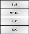
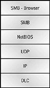
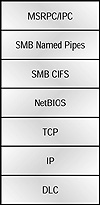
For reference purposes, Figures 7.4, 7.5, and 7.6 illustrate the relationships between NetBEUI/NetBIOS and NBT. Figure 7.4 shows the layers found in NetBEUI/NetBIOS, and Figure 7.5 reflects the browser function using NetBIOS over UDP. Figure 7.6 illustrates NetBIOS over TCP and the structure used when connecting to file systems (in this example, adding protocols to support Microsoft Exchange).

FIGURE 7.4 NetBIOS over NetBEUI

FIGURE 7.5 NetBIOS over UDP

FIGURE 7.6 NetBIOS over TCP/IP
Pure NetBEUI/NetBIOS installations may instinctively seem sufficient for very small networks, and designers would be correct in pointing out that the overhead and administration of this design would be reduced. However, the implementation also requires substantial modifications if and when either the network expands or direct Internet (via a firewall, preferably) connectivity is desired.
There are numerous methods for designing NetBIOS networks. However, this section encompasses only a few common configurations for reference.
NWLink in a Small Network
Figure 7.7 illustrates a small network designed to support NetBIOS using the IPX/NWLink protocol and includes both Novell servers and a PDC. This type of network design would be common in migrations from Novell NetWare to Windows NT, and it includes the use of the IP eXchange product from Cisco (now discontinued; this product is no longer used in most networks).

FIGURE 7.7 NWLink, NetBIOS, and IP eXchange
| Previous | Table of Contents | Next |