3-39
Cisco AVVID Network Infrastructure Enterprise Quality of Service Design
956467
Chapter 3 QoS in an AVVID-Enabled Campus Network
Selecting an Access-Layer Switch
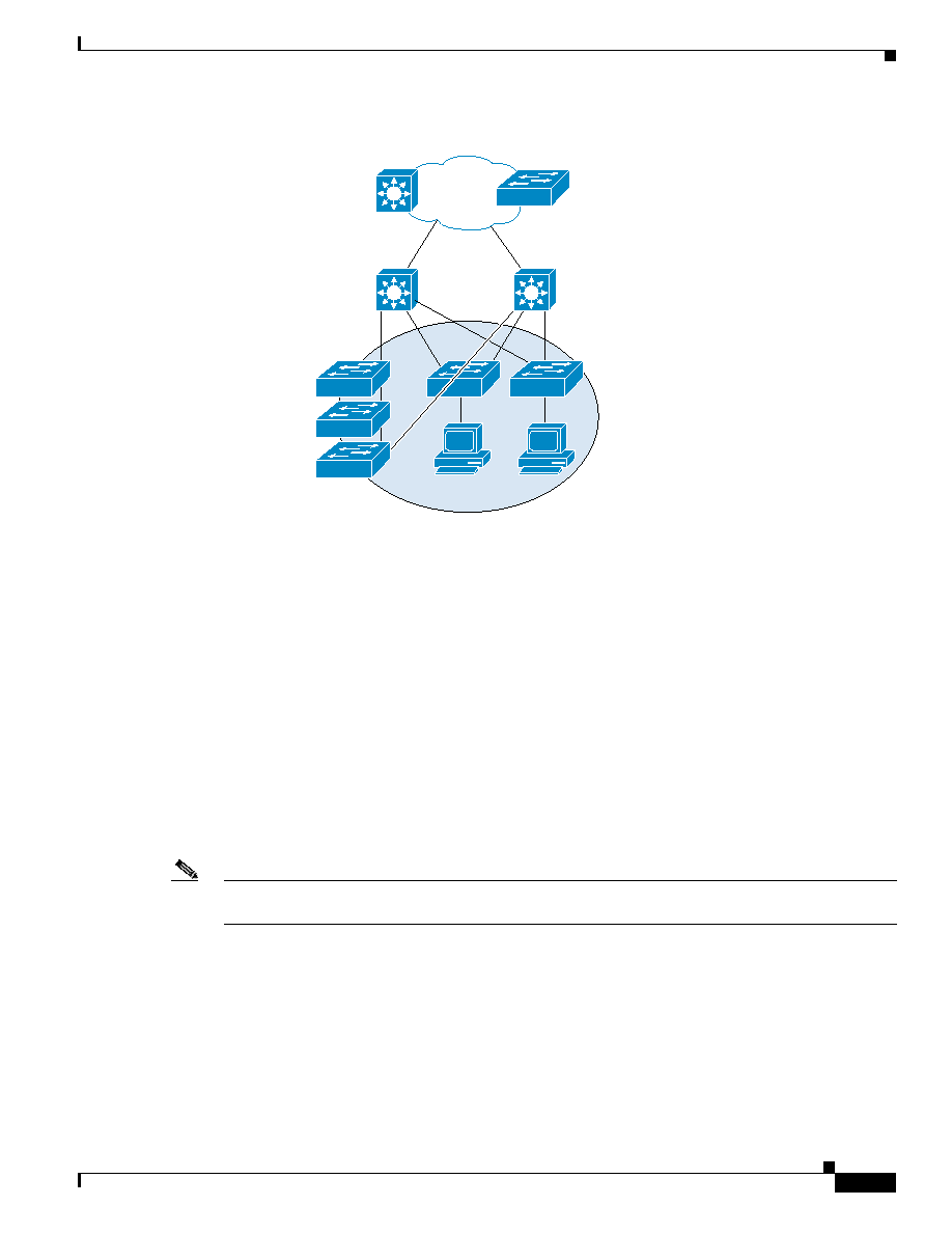
Figure 3-12 General Model for Catalyst 2950 QoS Configurations
This section presents suggested configurations for port scheduling and queuing on the Catalyst 2950. In
general:
·
The recommended configuration for the receive interface is 1Q-FIFO--one standard FIFO queue.
·
The recommended configuration for the transmit interface is 4Q1T--four standard queues with a
single threshold. Scheduling is done on a priority-scheduling basis or a WRR scheduling algorithm.
The default is priority scheduling. Admission to the queues is based on 802.1p CoS or port priority
CoS. The default queue admission criteria for the Catalyst 2950 are as follows: queue 1: CoS 0 and
1, queue 2: CoS 2 and 3, queue 3: CoS 4 and 5, queue 4: CoS 6 and 7.
For the Catalyst 2950, QoS requires the following changes to the access switch configuration:
1.
Modify the default CoS-to-DSCP mapping table.
2.
Configure an ACL that identifies mission critical traffic, associate it with a service policy, and apply
the policy to an interface.
3.
Enable QoS features to support an IP Phone.
4.
Enable QoS features required to support uplink to distribution layer.
Note
QoS is on by default in the Catalyst 2950. Priority queuing is the default. No change is required for the
CoS-to-queue assignment.
Modifying the CoS-to-DSCP Mappings
There are 8 CoS labels and 64 possible DSCP labels. To trust the CoS markings, the default
CoS-to-DSCP mapping table must be modified to equate CoS 3 (VoIP control traffic) to AF31, CoS 5
(VoIP bearer traffic) to EF, and CoS 4 to AF41.
Si
Si
VLAN=12
Core
Distribution
Access
Catalyst
6500
Catalyst 2950
74703
Si