vided in each header. This PDU information is only read by the peer layer on
the receiving device. After it's read, it's stripped off, and the data is then
handed to the next layer up.
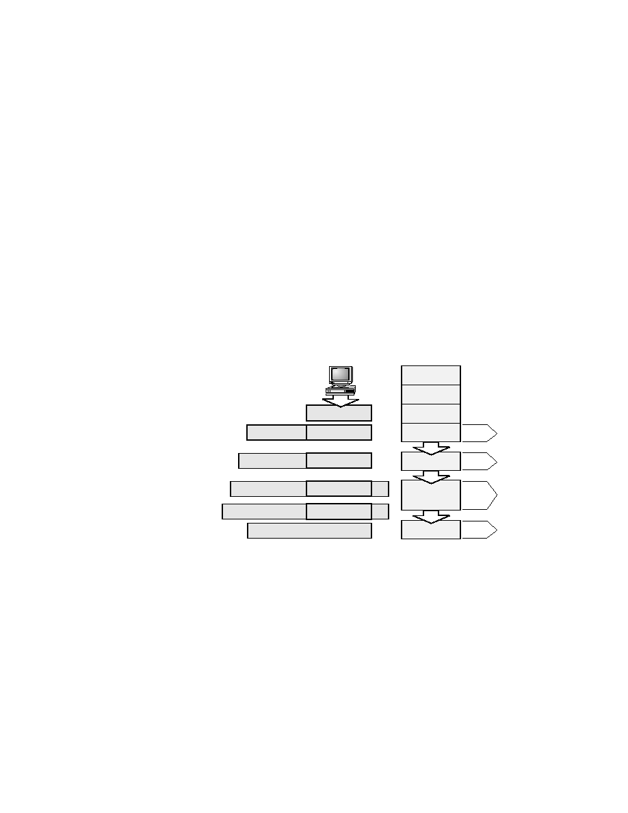
verted for transmission on the network. The data stream is then handed
down to the Transport layer, which sets up a virtual circuit to the receiving
device by sending over a synch packet. The data stream is then broken up
into smaller pieces, and a Transport layer header (a PDU) is created and
attached to the header of the data field; now the piece of data is called a seg-
ment. Each segment is sequenced so the data stream can be put back together
on the receiving side exactly as it was transmitted.
is used to get each segment to the correct network. The Network layer pro-
tocol adds a control header to the segment handed down from the Transport
layer, and what we have now is called a packet or datagram. Remember that
the Transport and Network layers work together to rebuild a data stream on
a receiving host, but it's not part of their work to place their PDUs on a local