Features of the 1900 Switch
597
Do not connect an Ethernet cable, ISDN, or live telephone line into the console
port. These can damage the electronics of the switch.
1900 Switch Startup
Before you power on the switch for the first time, check to make sure you
have completed the following:
You have plugged in all the network cables securely.
You have connected a terminal to the console port.
You have configured your terminal software correctly.
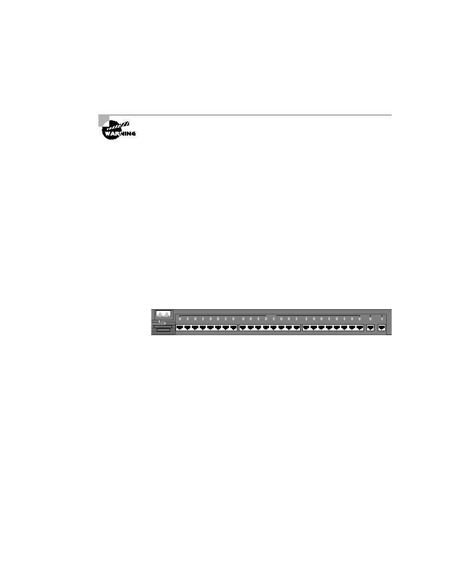
Once you have checked everything in this list, plug the power cable into
the switch and watch the light sequence. Then check the output on the con-
sole. Figure B.1 shows the 1900 switch and the light-emitting diode (LED)
locations.
F I G U R E B . 1
Catalyst 1900 switch
A green system light appears if the switch is operational. It will be amber
if a system malfunction has occurred. The RPS light is on if a redundant
power supply is detected in the switch.
The only button on the 1900 switch is the mode button. By pressing the
mode button, you can see three different status lights on the switch:
Stat
This light shows the status of the ports. If it is green, this indicates
a device is plugged into the switch. Green is active, and a green blinking
light is activity on the port. If the port is amber, there has been a link fault.
UTL
This light indicates the bandwidth of the switch. When you press
the mode button on a 1912 switch, and the LEDs for ports 1 through 4
come on, this means the bandwidth utilization of the switch is somewhere
between 0.1 and 1.5Mbps. If lights 5 through 8 come on, this indicates
YSTEM
RPS
1x
2x
3x
4x
5x
6x
7x
8x
9x
10x
11x
12x
13x
14x
15x
16x
17x
18x
19x
20x
21x
22x
23x
24x
10BaseT
MODE
CISCO YSTEMS
S
UTL FDUP
STAT
Catalyst 1900
Ax
Bx
100BaseTX
Copyright ©2002 SYBEX, Inc., Alameda, CA
www.sybex.com