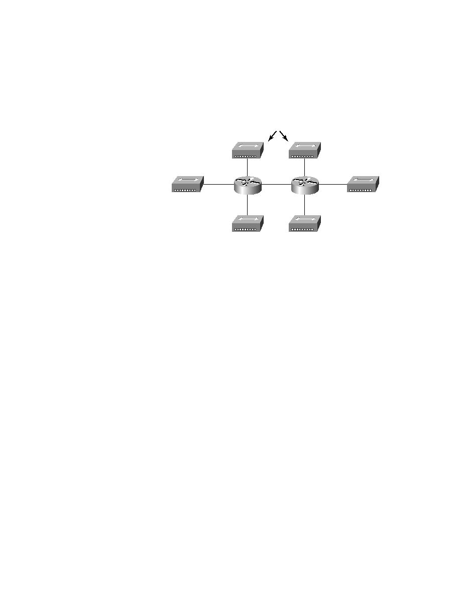
not obvious from the figure). Each node attached to a particular physical net-
work had to match that network number in order to be able to communicate
on the internetwork. Notice that each department had its own LAN, so if you
needed to add new users to Sales, for example, you would just plug them into
the Sales LAN and they would automatically be part of the Sales collision and
broadcast domain. This design really did work well for many years.
if there's no more physical space in the location where the Sales team is
located for this new employee? Well, let's say there just happens to be
plenty of room in the Finance section of the building. That new Sales team
member will just have to sit on the same side of the building as the Finance
people, and we'll just plug the poor soul into the hub for Finance.
issue, because this new user is a member of the Finance broadcast domain
and can therefore see all the same servers and network services that all of the
Finance folks can. Secondly, for this user to access the Sales network services
they need to get the job done, they would need to go through the router to
login to the Sales server--not exactly efficient!