Introduction to VLANs
321
Introduction to VLANs
A
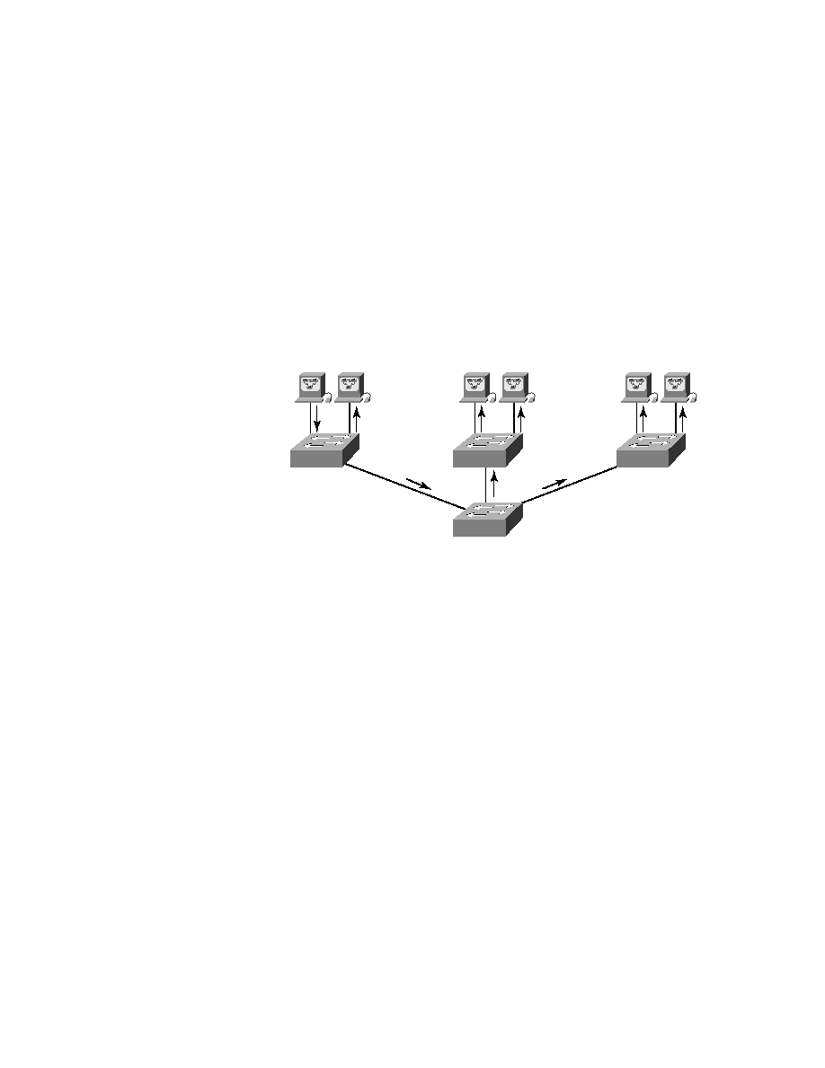
s shown in Figure 6.1, layer-2 switched networks are typically
designed as a flat network. Every broadcast packet transmitted is seen by
every device on the network, regardless of whether the device needs to
receive that data or not.
F I G U R E 6 . 1
Flat network structure
By default, routers allow broadcasts only within the originating network,
but switches forward broadcasts to all segments. The reason it's called a
flat
network
is because it's one
broadcast domain
, not because its design is phys-
ically flat.
In Figure 6.1 we see Host A sending a broadcast and all ports on all switches
forwarding this broadcast, except the port that originally received it. Now look
at Figure 6.2, which pictures a switched network. It shows Host A sending a
frame with Host D as its destination, and as you can see, that frame is only
forwarded out the port where Host D is located. This is a huge improvement
over the old hub networks, unless having one
collision domain
by default is
what you really want.
Now you already know that the largest benefit gained by having a layer-2
switched network is that it creates individual collision domain segments
for each device plugged into the switch. This scenario frees us from the
Ethernet distance constraints, so now larger networks can be built. But
with each new advance, we often encounter new issues--the larger the
number of users and devices, the more broadcasts and packets each switch
must handle!
Host A
Copyright ©2002 SYBEX, Inc., Alameda, CA
www.sybex.com