676 Chapter 9: Scenarios for Final Preparation
4
Plan the location and logic of SAP filters. Ensure that Server 3 is accessed only by clients
on the Ethernet off R2.
5
After your subnet numbers are chosen, calculate the broadcast addresses and the range of
valid IP addresses in each subnet. Use Table 9-12, if convenient.
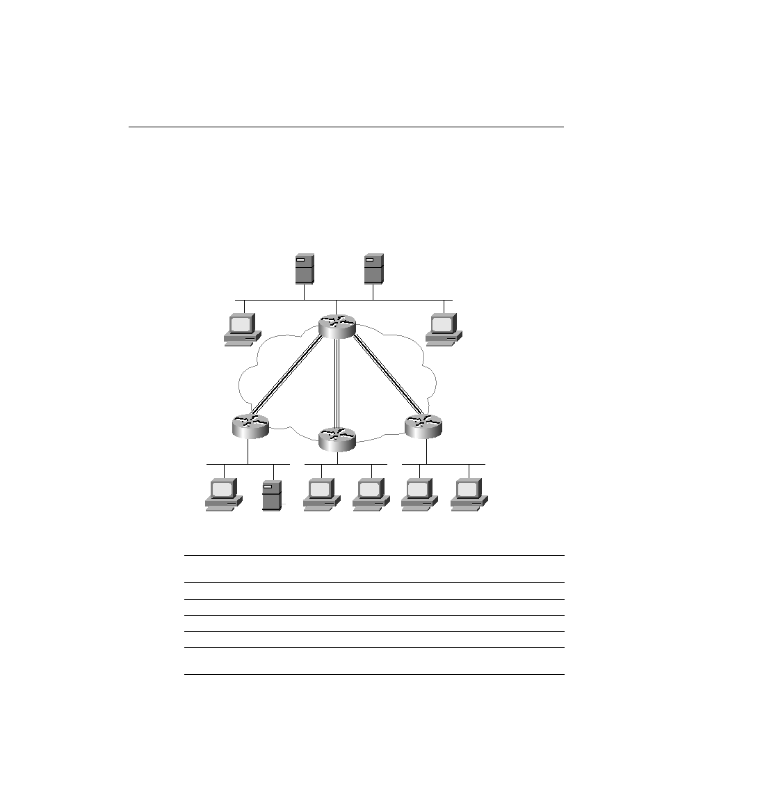
Figure 9-5
Scenario 9-3 Network Diagram
Table 9-10
Scenario 9-3, Part A--IP Subnet and IPX Network Planning Chart
Location of Subnet/
Network Geographically
Subnet Mask
Subnet Number
IPX Network
Ethernet off R1
Ethernet off R2
Ethernet off R3
Ethernet off R4
Virtual circuit between R1
and R2
PC21
Server 3
PC11
DLCI 301
PC12
PC31
PC32
PC41
PC42
s0
s0
s0
s0
R1
DLCI 303
R2
R3
R4
DLCI 304
Frame Relay
Partial Mesh
Server 1
Server 2
DLCI 302
ch09.fm Page 676 Monday, March 20, 2000 5:23 PM