642
Chapter 9: Scenarios for Final Preparation
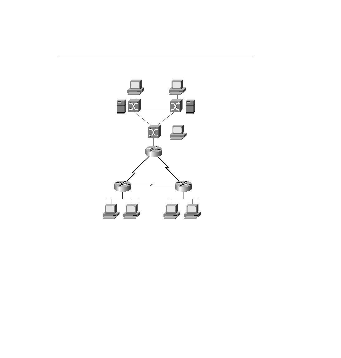
Figure 9-2
Scenario 9-1 Network Diagram
4
Plan the location and logic of SAP filters to prevent clients on the Ethernet off R2 from
logging in to Server 2. Again, do not create the configuration, but simply make notes about
the logic and location of the access lists.
Assume that a single VLAN is used on the switches near Router 1 (R1).
Table 9-1 and Table 9-2 are provided as a convenient place to record your IP subnets, IPX
networks, and IP addresses when performing the planning tasks for this scenario.
PC11
Server 1
PC12
Server 2
Server 3
PC13
S0
S0
S0
S1
S1
S1
SW3
e1/0
e1/0
e1/0
SW1
SW2
e1/1
e1/1
e1/1
R2
e0
e0
e0
R1
R3
PC21
PC32
PC31
ch09.fm Page 642 Monday, March 20, 2000 5:23 PM