636 Chapter 8: WAN Protocols and Design
Answers to Scenario 8-5: Frame Relay Configuration
Dissection
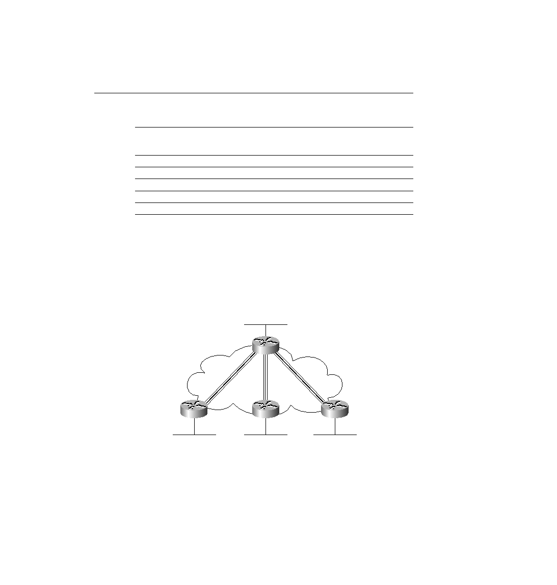
Figure 8-43 supplies the network diagram described in Scenario 8-5. The subinterfaces are all
point-to-point, which is a clue that each VC has a subnet and IPX network associated with it.
An examination of the IP addresses or IPX network numbers should have been enough to
deduce which routers are attached to each end of each VC.
Figure 8-43
Diagram to Scenario 8-5 Frame Relay Network
Split horizon is turned off on all interfaces because that is the default with point-to-point
subinterfaces and because no command has been configured to turn it on.
Cisco encapsulation was used in each case. The encapsulation frame-relay command defaults
to the use of Cisco encapsulation.
Table 8-58
Scenario 8-4 IP and IPX Routing Table Contents, Router A
Layer 3 Group
Outgoing Interface
Next-Hop IP
Address, or
Connected
Next-Hop IPX
Address, or
Connected
101
E0
Connected
Connected
102
S0.2
168.15.202.2
202.0200.bbbb.bbbb
103
S0.3
168.15.203.3
203.0200.cccc.cccc
104
S0.4
168.15.204.4
204.0200.dddd.dddd
105
S0.5
168.15.205.5
205.0200.eeee.eeee
Atlanta
Boston
Charlotte
180.1.10.0
AAA18010
Frame Relay
Partial Mesh
180.1.13.0
AAA18013
180.1.11.0
AAA18011
Nashville
180.1.12.0
AAA18012
s0
s0
s0
s0
.1
180.1.1.0
AAA1801
180.1.2.0
AAA1802
180.1.3.0
AAA1803
ch08.fm Page 636 Monday, March 20, 2000 5:17 PM