546 Chapter 8: WAN Protocols and Design
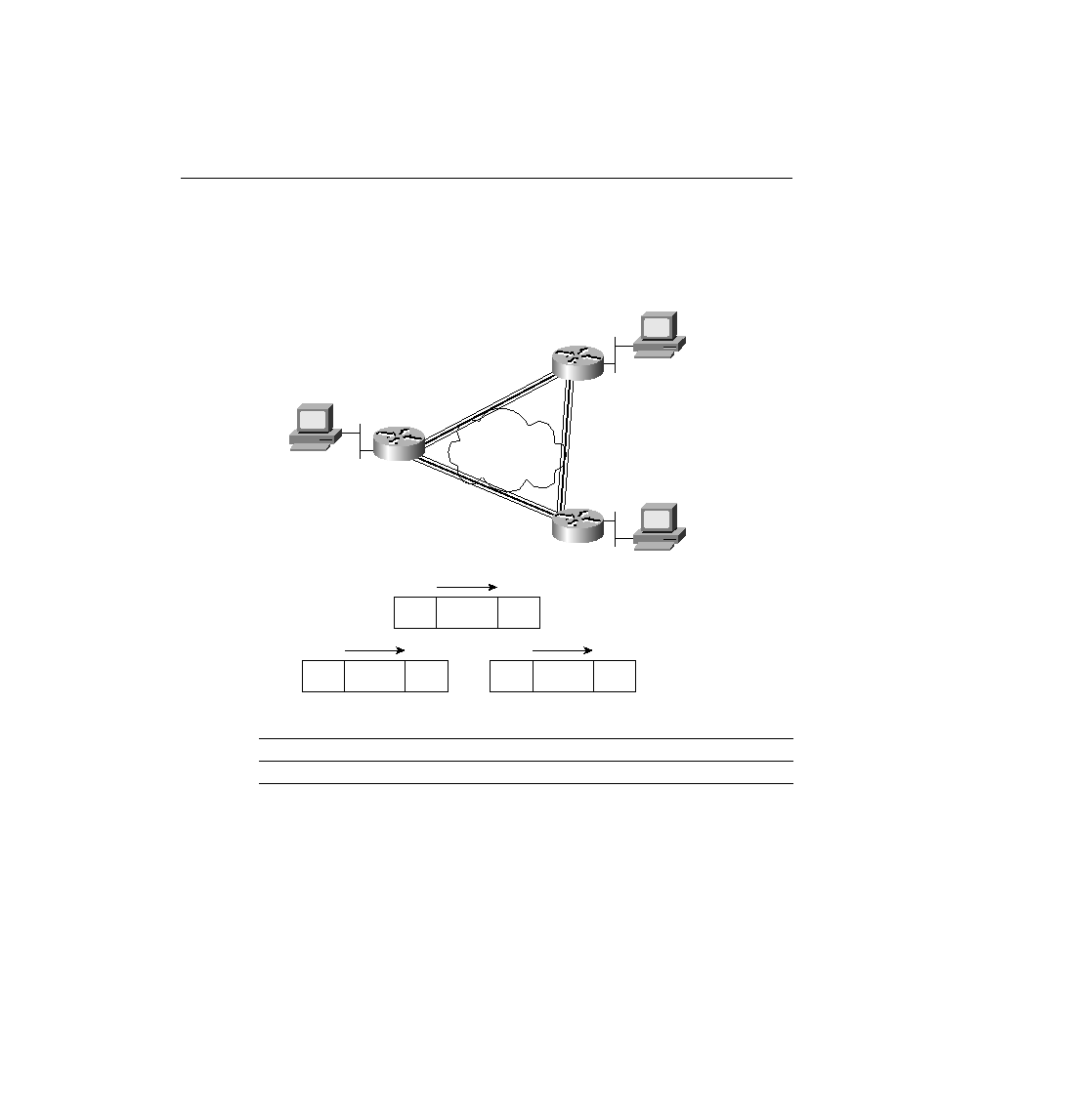
Now consider the Frame Relay network in Figure 8-16, along with the routing table in
Table 8-19.
Figure 8-16
Basic Frame Relay Network
Again consider the core routing logic. Router A receives an Ethernet frame from some host and
strips the Ethernet header (and trailer). It decides to route the packet out serial 0 to the next
router, 10.1.2.2 (Router B's S0 IP address). Router A builds the Frame Relay header/trailer and
sends the frame.
Although Router A knows the serial interfaces out which to forward the frame, Router A does
not know the correct DLCI yet. A mapping is needed in Router A to correlate 10.1.2.2 (Router
B) and the DLCI Router A used to reach Router B. However, the same IP ARP used on LANs
Table 8-19
Partial Routing Table on Router A for Figure 8-16
Subnet
Outgoing Interface
Next Router
10.1.3.0
Serial 0
10.1.2.2
FR
L3 Packet
FR
Eth.
L3 Packet
Eth.
Eth.
L3 Packet
Eth.
10.1.3.0/24
10.1.1.0/24
10.1.4.0/24
DLCI 40
.1
DLCI 41
.2
.3
DLCI 42
Brice
Maggie
Gary
10.1.2.0/24
A
B
C
ch08.fm Page 546 Monday, March 20, 2000 5:17 PM